REPAIRING AND NOT THROWING AWAY

Richtige Fernseher haben Röhren!

Richtige Fernseher haben Röhren!

In Brief: On this site you will find pictures and technical information about Service Modes, Circuit Diagrams, Firmware Update procedure, Disassemble procedure, Universal remote control set-up codes, Troubleshooting and more....

If you go into the profession, you will obtain or have access to a variety of tech tips databases HERE IT IS Master Electronics Repair !.

These are an excellent investment where the saying: 'time-is-money' rules. However, to learn, you need to develop a general troubleshooting approach - a logical, methodical, method of narrowing down the problem. A tech tip database might suggest: 'Replace C536' for a particular symptom. This is good advice for a specific problem on one model. However, what you really want to understand is why C536 was the cause and how to pinpoint the culprit in general even if you don't have a service manual or schematic and your tech tip database doesn't have an entry for your sick TV or VCR.

While schematics are nice, you won't always have them or be able to justify the purchase for a one-of repair. Therefore, in many cases, some reverse engineering will be necessary. The time will be well spent since even if you don't see another instance of the same model in your entire lifetime, you will have learned something in the process that can be applied to other equipment problems.
As always, when you get stuck, checking out a tech-tips database may quickly identify your problem and solution.In that case, you can greatly simplify your troubleshooting or at least confirm a diagnosis before ordering parts.

Happy repairing!
Today, the West is headed for the abyss. For the ultimate fate of our disposable society is for that society itself to be disposed of. And this will happen sooner, rather than later.

How to use the site:

- If you landed here via any Search Engine, you will get what you searched for and you can search more using the search this blog feature provided by Google. You can visit more posts scrolling the left blog archive of all posts of the month/year,
or you can click on the main photo-page to start from the main page. Doing so it starts from the most recent post to the older post simple clicking on the Older Post button on the bottom of each page after reading , post after post.

You can even visit all posts, time to time, when reaching the bottom end of each page and click on the Older Post button.

- If you arrived here at the main page via bookmark you can visit all the site scrolling the left blog archive of all posts of the month/year pointing were you want , or more simple You can even visit all blog posts, from newer to older, clicking at the end of each bottom page on the Older Post button.
So you can see all the blog/site content surfing all pages in it.

- The search this blog feature provided by Google is a real search engine. If you're pointing particular things it will search IT for you; or you can place a brand name in the search query at your choice and visit all results page by page. It's useful since the content of the site is very large.

Note that if you don't find what you searched for, try it after a period of time; the site is a never ending job !

..............The bitterness of poor quality is remembered long after the sweetness of todays funny gadgets low price has faded from memory........ . . . . . .....
Don't forget the past, the end of the world is upon us! Pretty soon it will all turn to dust!

©2010, 2011, 2012, 2013, 2014 Frank Sharp - You do not have permission to copy photos and words from this blog, and any content may be never used it for auctions or commercial purposes, however feel free to post anything you see here with a courtesy link back, btw a link to the original post here , is mandatory.
All posts are presented here for informative, historical and educative purposes as applicable within fair use. NOTHING HERE IS FOR SALE !

Showing posts with label HARPER. Show all posts

Monday, 3 August 2020

REPAIRING / SERVICING TV HARPER 16R575

Technical description and composition of the HARPER 16R575 TV, panel type and modules used. The composition of the modules.
HARPER LED
Model: 16R575
Chassis / Version: HK.T.RDA8501CV03
Panel: NT156WHM-N32 V8.0
LED backlight: EDGE LED
T-CON: NT156WHM-N11 / N21 47-6001308
LED driver (backlight): integrated into MainBoard
Power Supply (PSU): Adapter 12V
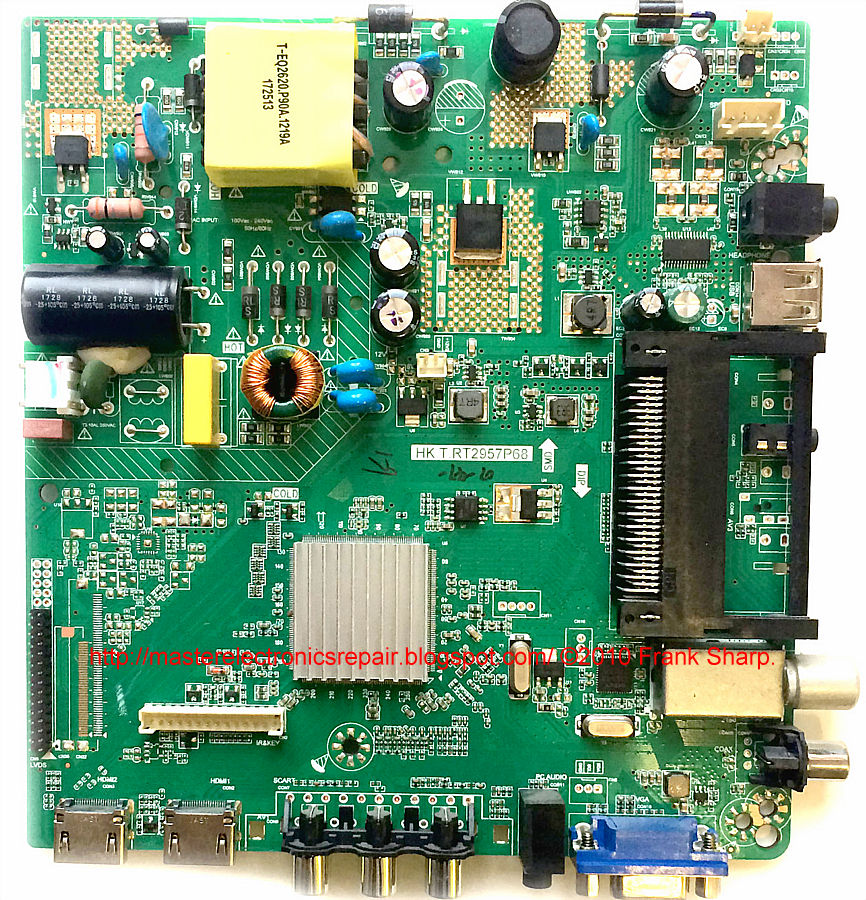
MainBoard: HK.T.RDA8501CV03
IC MainBoard: SPI FLASH: 25Q32, AUDIO: YD1517
Tuner: NoName
Specifications 16R575
HARPER 16R575
General recommendations for TV LCD LED repair
Possible manifestations of defects
- TV HARPER 16R575 does not turn on and does not show any signs of operability at all. No response to the remote control and front panel control buttons.
With such manifestations, the adapter power supply usually fails.
External power supply Adapter 12V is not always subject to repair, especially since the owner can purchase it on his own. But, in some cases, it makes sense to open it and eliminate simple typical defects inherent in converters in pulse sources. It is necessary to measure its output supply voltages, and in case of their absence, check the serviceability of the power switches of the converters and rectifier diodes for the probability of breakdown in semiconductor PN junctions.
In case of any breakdown of semiconductors in the secondary circuits, the converter can usually operate normally in an emergency short circuit mode. There are no output voltages. And with a short circuit in the power elements of the primary circuit, as a rule, the mains fuse breaks and, less often, the current sensor in the source of the key.
Breakdown of power switches (MosFet) in switching sources is sometimes caused by malfunctions of other circuit elements, for example, in the circuits supplying the PWM controller, frequency setting or damper, as well as in the circuits of Negative Feedback (OOS) stabilization. PWM controllers (PWM), if they do not have visible damage to the case and an outright short circuit between the terminals, are usually checked by replacing.
- There is no picture, there is sound, it reacts to the remote control, the channels are switched. In some cases, the image appears when turned on and disappears immediately.
A malfunction is usually in these cases most likely in the backlight units of the display matrix. The reason for this may be an open circuit in the LED circuit, or a problem in stabilizing their power supply.
It should be remembered that it is not possible to determine an open circuit in the LED lines without disassembling the panels using a tester or multimeter without an additional device, for example, a current source. To open all PN junctions connected in series at once, a voltage of several tens of volts may be required. Then you need to open the panel and check each LED separately with a multimeter. If the capabilities of your multimeter do not allow you to open the LED in the forward direction, or dual LEds are used, then the PN transition of the emergency zener diode can indirectly serve as an indicator of serviceability. In the event of a malfunction of the LED-a, the PN-transition of the zener diode will either be cut off or broken through in the SC.
- The indicator blinks or is on constantly, the TV does not turn on, does not respond to the remote control.
Repair or diagnostics of the HK.T.RDA8501C motherboard should begin with checking the stabilizers and power converters necessary to power the microcircuits and matrix. If necessary, you should update or replace the software (software). Complex repair of MB (SSB) is possible only in a service center with the necessary equipment. Checking or replacing SPI FLASH: 25Q32, AUDIO: YD1517 elements requires the necessary training and professional skills to repair modules at the component level. Problems associated with the use of BGA soldering technologies can sometimes be diagnosed by the warm-up method.
If there is no reception of TV channels, but the TV is working properly from external devices, first of all, you need to check the supply voltage of the NoName tuner and update the software. I2C communication pulses must be monitored with an oscilloscope.
Remember! Attempts to self-repair the HARPER 16R575 TV, in the absence of the necessary qualifications and experience, are categorically not recommended and are fraught with negative consequences, up to the complete non-repairability of the device!


DOWNLOAD FIRMWARE FOR SPI FLASH  ----------->   HARPER 16R575, Main: HK.T.RDA8501C V03, Panel: NT156WHM-N32 V8.0

 The appearance of the MainBoard HK.T.RDA8501CV03 is shown in the figure below:
HK.T.RDA8501CV03
The main features of the HARPER 16R575 device:
Installed matrix (LED-panel) NT156WHM-N32 V8.0.
Matrix control uses NT156WHM-N11 Timing Controller (T-CON).
A converter combined with the HK.T.RDA8501CV03 main board is used to power the backlight LEDs.
To power all the internal components of the HARPER 16R575 TV, an external adapter type 12V is used.
MainBoard - the main board (motherboard) is a HK.T.RDA8501CV03 module, using SPI FLASH: 25Q32, AUDIO: YD1517 and others.
Tuner NoName provides reception of television programs and tuning to channels.
HARPER 16R575 TV with LCD NT156WHM-N32, diagonal size 15.6 "(40 cm) 16: 9. The required screen brightness of 180 cd / m² is provided by LED backlighting. Dynamic contrast ratio of 40,000: 1 is achieved by special control of the LEDs. LED backlighting technology for this TV model.It is possible to view images in high quality HD at a resolution of 1366x768 pixels in a graphic resolution of 720p (HD Ready) Supported multimedia file formats: MP3, WMA, MPEG4, Xvid, DivX, MKV, JPEG ...
Speaker power 10 W (2x5 W) is provided by two speakers. The NICAM STEREO audio processing system is used.
External interface (communication with other devices) is supported by standard input and output connectors: antenna input (RF), AV, audio x2, component, VGA, HDMI, USB. A headphone output is provided.
The power consumed by the TV operating in mains mode is 20 W.
Dimensions: with stand 375x280x140 mm, without stand 375x240x45 mm.
TV weight: 1.2 kg.
Attention! HARPER 16R575 LED TV panel NT156WHM-N32 V8.0 is an expensive and unreliable element.
Do not allow any impacts on the glass and pressure on the screen surface to avoid damage to the LED panel!
It is also unsafe for liquid to spill onto the screen. Sometimes one drop is enough if it drips down the glass onto the cables to make the TV non-repairable.

REPAIRING / SERVICING TV HARPER 20R575T

Technical description and composition of the HARPER 20R575T TV, panel type and modules used. The composition of the modules.
HARPER LED
Model: 20R575T
Chassis / Version: HK.T.RT2957P65
Panel: T195XVN01.0 // KM0195LDAH0027
LED backlight: SJ.HZ.D1950401-2835BS-M 1.14.MD195004
LED driver (backlight): integrated into MainBoard
PWM LED driver: 8 pin
MOSFET LED driver: TO-252
Power Supply (PSU): integrated into MainBoard
PWM Power: PWM SOT23-6
MOSFET Power: TO-252
MainBoard: HK-T.RT2957P65
IC MainBoard: CPU RT2957P65, Flash 25Q64BV
Tuner: TDA18275
Specifications 20R575T
HARPER 20R575T
General recommendations for TV LCD LED repair
Possible manifestations of defects
- HARPER 20R575T does not turn on, indicators on the front panel do not light or flash. The TV does not respond to control buttons and the remote control.
A malfunction in such cases should be looked for primarily in the circuit of a switching power supply (SMPS) - a converter (AC / DC) of the mains voltage, which is combined with the MainBoard HK-T.RT2957P65 in this model. It is necessary to measure the output voltages in its secondary circuits, and if they are completely absent, the serviceability of the power switches (TO-252) and rectifier diodes should be checked for a possible breakdown (short circuit).
In case of breakdowns of semiconductors in the secondary circuits of any converter, as a rule, it can operate in an emergency mode of short circuit without output voltages, and with a short circuit in the elements of the primary circuit, the mains fuse most often breaks off immediately and, less often, the current sensor in the source of the key.
Mos-Fet power switches used in switching power supplies sometimes fail due to a malfunction of any other elements that can disable it in the key mode, or create an excess of the maximum permissible key parameters. These can be elements supplying a PWM regulator, frequency setting or damper circuits, or elements of negative feedback in the stabilization circuit. PWM controllers PWM SOT23-6, in the absence of visible damage or outright short circuits between the terminals, are checked by replacing them with new ones, or knowingly working properly.
- There is no picture, but there is sound and all other TV functions are working. The image sometimes appears for a second immediately after switching on and disappears.
As a rule, in such cases there is no display backlight. Usually the cause of the malfunction is in the breakage of the LEDs, or in the connectors of the LED strips, but sometimes the LED driver is also faulty.
Without a special current source, it is impossible to check the line of LEDs connected in series, and it is unsafe for them to use any voltage sources above 12V for this purpose. Then all that remains is to open the panel and check each LED separately. Typically, Chinese multimeters with a 9V power supply lightly light up one 3-volt LED, if you connect the probes to it in the forward direction, the red probe to the anode, the black one to the cathode. For dual 6-volt LEDs, the PN junction of its emergency zener diode can serve as an indicator of LED health. In the event of a malfunction of the LED, its zener diode will either be cut off or broken into the K / Z.
- The TV does not turn on, does not respond to the remote control. The indicator blinks or signals the standby mode.
Repair or diagnostics of the HK-T.RT2957P65 motherboard should begin with checking the stabilizers and power converters necessary to power the microcircuits and matrix. If necessary, you should update or replace the software (software). Often the MB (SSB) board needs to be replaced in case of complex malfunctions that are difficult to detect. When trying to repair, you should check its elements - CPU RT2957P65, Flash 25Q64BV and replace the failed chips with new ones. Some malfunctions may be associated with the use of BGA soldering technologies in modern Main Board. Typically, such defects are detected by local heating of the chip.
If you suspect a malfunction of the TDA18275 tuner, first of all, you need to make sure the software is correct, as well as the presence of the required supply voltage levels and pulses of data exchange with the processor via the I2C bus at the corresponding tuner pins.
Users and owners of TVs should remember that attempts to self-repair the HARPER 20R575T TV without the appropriate qualifications and the necessary experience can lead to serious negative consequences!

DOWNLOAD FIRMWARE FOR SPI FLASH  ----------->   HARPER 20R575T, Main: HK-T.RT2957P65, Panel: KM0195LDAH0027 T195XVN01.0

 The appearance of the MainBoard HK-T.RT2957P65 is shown in the figure below:
HK-T.RT2957P65
HK-T.RT2957P65 can be used in TVs:
SUPRA STV-LC19T860WL (Panel LC185TT6A), SUPRA STV-LC22T860FL (Panel LC215DTCA).
The main features of the HARPER 20R575T device:
Installed matrix (LED panel) T195XVN01.0 or KM0195LDAH0027.
To power the backlight LEDs, a converter combined with the HK-T.RT2957P65 main board is used, controlled by an 8 pin PWM controller. TO-252 switches are used as power elements of the LED driver.
The power module is combined with the MainBoard and is made according to the AC / DC flyback voltage converter using PWM SOT23-6 microcircuits and TO-252 power switches.
MainBoard - the main board (motherboard) is a HK-T.RT2957P65 module, using CPU RT2957P65, Flash 25Q64BV and others.
The TDA18275 tuner provides reception of television programs and tuning to channels.
HARPER 20R575T TV with LCD T195XVN01.0, 19.6 "(50 cm) diagonal, 16: 9 format. The required screen brightness of 180 cd / m² is provided by LED backlighting. Dynamic contrast ratio of 40,000: 1 is achieved by special LED control. screen manufacturing technology of this TV model is realized with LED backlighting.It is possible to view images in high quality HD at a resolution of 1366x768 pixels in the standard of graphic decomposition 720p (HD Ready ).Supported multimedia file formats: MP3, MPEG4, JPEG.
The power of the sound system of 6 W (2x3 W) is provided by two speakers. The NICAM STEREO audio processing system is used.
External interface (communication with other devices) is supported by standard input and output connectors: antenna input (RF), AV, audio x2, component, VGA, HDMI, USB. A headphone output is provided.
The digital tuner is capable of receiving TV channels in the DVB-T MPEG4, DVB-C, DVB-T2 standards.
The power consumed by the TV operating in mains mode is 36 W.
Dimensions: with stand 458x303x153 mm, without stand 458x268x66 mm.
TV weight: 1.7 kg.
Attention! HARPER 20R575T LED TV panel T195XVN01.0 is an expensive and unreliable element.
Do not allow any impacts on the glass and pressure on the screen surface to avoid damage to the LED panel!
It is also unsafe for liquid to spill onto the screen. Sometimes one drop is enough if it drips down the glass onto the cables to make the TV non-repairable.

REPAIRING / SERVICING TV HARPER 22F0530

Technical description and composition of the HARPER 22F0530 TV, panel type and modules used. The composition of the modules.
HARPER LED
Model: 22F0530
Chassis / Version: T.VST59.A81
Panel: CX215DLEDM
LED backlight: 180.DT0-2219D00-0H HL-00215A28-0601S-01 A
T-CON: 21M07-C04 M215HVN01.0 Ctrl BD
LED driver (backlight): integrated into PSU
PWM LED driver: OB3350CP
MOSFET LED driver: AOD450
Power Supply (PSU): MP24S-CX
PWM Power: OB2273
MOSFET Power: TO-220
MainBoard: T.VST59.A81
IC MainBoard: CPU: TSUMV59XU-Z1, SPI FLASH: 25Q32, Audio: YD1517P
Tuner: Noname
Control: IR: 200-GJR-LE32190
Specifications 22F0530
HARPER 22F0530
General recommendations for TV LCD LED repair
Possible manifestations of malfunctions
- HARPER 22F0530 does not turn on, does not respond to buttons and the remote control, indicators on the front panel do not light or flash.
In some of these cases, a malfunction is detected in the MP24S-CX power supply module. Then we recommend measuring its output voltages and, if they are absent, check the serviceability of the power switches (TO-220) and rectifier diodes of the converters for a possible short circuit.
In case of breakdowns in the secondary circuits, the converter, as a rule, can operate in an emergency in the short-circuit mode, and in the event of a short circuit in the power elements of the primary circuit, the mains fuse is usually cut off.
Mos-Fet power switches used in switching power supplies sometimes fail due to a malfunction of any other elements that can disable it in the key mode, or create an excess of the maximum permissible key parameters. These can be elements supplying a PWM regulator, frequency setting or damper circuits, or elements of negative feedback in the stabilization circuit. PWM controllers OB2273, in the absence of visible damage or outright short circuits between the terminals, are checked by replacing them with new ones, or known to be working properly.
- No picture, sound, all other TV functions work. When turned on, the image may sometimes appear for a second.
Most likely in these cases is a malfunction of the LED backlight. Often the reason is a malfunction of the LEDs (open circuit, short circuit ...), or the connectors of the strips (strings), less often the LED driver turns out to be faulty.
It is impossible to check the LED bars for a break without disassembling the panel with a multimeter or tester. For these purposes, it is necessary to open all series-connected PN junctions and a voltage of the order of tens of volts will be required, and ideally a current source. Having disassembled the panel, it is necessary to check each LED separately. Chinese multimeters tend to light a single 3V LED in the forward direction. In the case of using dual 6-volt LEDs, the PN junction of its protective zener diode can serve as an indicator of serviceability. In faulty LEDs, the zener diode will either be cut off, or pierced in the K / Z.
- The TV does not turn on, the indicator signals standby or operating mode, or blinks.
Repair or diagnostics of the T.VST59.A81 motherboard should begin with checking the stabilizers and power converters required to power the microcircuits and matrix. If necessary, you should update or replace the software (software). If it is not possible to replace the MB (SSB) board, you must check the serviceability of its elements - CPU: TSUMV59XU-Z1, SPI FLASH: 25Q32, Audio: YD1517P. Defective components must be replaced.
Before changing the Noname tuner, if it is not possible to tune to television channels, you should make sure that there are supply voltages, which must be measured at the corresponding tuner terminals and check the software for correctness. The pulses of the data exchange of the tuner with the processor can be monitored with an oscilloscope


Attention to TV owners! Attempts to repair HARPER 22F0530 yourself are not recommended by the manufacturer and can lead to serious negative consequences!


The appearance of the MainBoard T.VST59.A81 is shown in the figure below:
T.VST59.A81
External view of the power supply
Main features of the HARPER 22F0530 device:
Installed matrix (LED panel) CX215DLEDM.
Matrix control uses Timing Controller (T-CON) 21M07-C04.
A converter combined with a power supply is used to power the backlight LEDs, and is controlled by the OB3350CP PWM controller. The keys of the AOD450 type are used as power elements of the LED driver.
The formation of the necessary supply voltages for all nodes of the HARPER 22F0530 TV is carried out by the MP24S-CX power module, or its analogs using OB2273 microcircuits and TO-220 power switches.
MainBoard - the main board (motherboard) is a T.VST59.A81 module, using CPU chips: TSUMV59XU-Z1, SPI FLASH: 25Q32, Audio: YD1517P and others.

Tuner Noname provides reception of television programs and tuning to channels.
HARPER 22F0530 TV with LCD CX215DLEDM, diagonal size 22 "(56 cm) 16: 9. The required screen brightness of 180 cd / m² is provided by LED backlighting. Contrast, as the ratio of maximum brightness to minimum, is 2000: 1. The LED panel of this TV is equipped with edge LED backlighting.The design and technical capabilities of the TV provide viewing of broadcasts and movies in high quality HD at a resolution of 1920x1080 pixels in graphic resolution according to the standard 1080p (Full HD) .Input high-frequency or video signal can be processed in analog systems PAL, SECAM, NTSC Graphic processing and digital signal shaping occurs in 480i, 480p, 576i, 576p, 720p, 1080i standards Supported multimedia file formats: MP3, WMA, MPEG4, DivX, MKV, JPEG.

Speaker power of 6 W (2x3 W) is provided by two speakers. The NICAM STEREO audio processing system is used.
External interface (communication with other devices) is supported by standard input and output connectors: antenna input (RF), VGA, USB. A headphone output is provided. To connect a computer or laptop to this TV model, a VGA (D-Sub 15) connector on the TV case is used, this interface supports resolutions: 640x480, 800x600, 1024x768, 1280x1024, 1360x768.
Overall dimensions: 509x343x175 mm.
TV weight: 2.4 kg.

Attention! Panel CX215DLEDM LED TV HARPER 22F0530 is an expensive and unreliable element.
Do not allow any impacts on the glass and pressure on the screen surface to avoid damage to the LED panel!
It is also unsafe for liquid to spill onto the screen. Sometimes one drop is enough if it drips down the glass onto the cables to make the TV non-repairable.

REPAIRING / SERVICING TV HARPER 24F470T

Technical description and composition of the HARPER 24F470T TV, panel type and modules used. The composition of the modules.
HARPER LED
Model: 24F470T
Chassis / Version: TP.S512.PA63
Panel: CX236DLEDM
LED driver (backlight): integrated into MainBoard
PWM LED driver: SN51DP
MOSFET LED driver: PA1108DA
Power Supply (PSU): integrated into MainBoard
PWM Power: LD5530
MOSFET Power: TO-252
MainBoard: TP.S512.PA63
IC MainBoard: CPU: S2T512, SPI Flash: GD25Q64, Audio: YD1517P
Tuner: XF-3SDT-H (R840)
Specifications 24F470T
HARPER 24F470T
General recommendations for TV LCD LED repair
Possible malfunctions
- TV HARPER 24F470T does not turn on and does not give any signs of turning on, does not respond to control buttons and to the remote control.
First of all, in such cases, you should make sure that the common switching power supply (SMPS) - the AC / DC voltage converter of the mains voltage - is working. All source elements in this TV model are located on the MainBoard TP.S512.PA63. Its output voltages should be measured and, if they are absent, the serviceability of the power switches (TO-252) and rectifier diodes in the converters should be checked for possible breakdown.
In case of breakdowns in the secondary circuits, the converter can operate in short-circuit mode, and in case of short-circuit in the elements of the primary circuit, the mains fuse usually breaks.
Mos-Fet power switches used in switching power supplies sometimes fail due to a malfunction of any other elements that can disable it in the key mode, or create an excess of the maximum permissible key parameters. These can be elements supplying a PWM regulator, frequency setting or damper circuits, or elements of negative feedback in the stabilization circuit. PWM controllers LD5530, in the absence of visible damage or outright short circuits between the terminals, are checked by replacing them with new ones, or known to be in good working order.
- There is no image, there is sound, it reacts to the remote control. Or, immediately after switching on for a second, the image may appear and immediately disappear.
Usually, in such cases, a malfunction is detected in the nodes of the backlight of the LED panel. The reason may be in the breakage of the LEDs, in the stabilization of their power supply, or in the violation of the contact connections of the strings connectors,
Without a special current source, it is impossible to check the line of LEDs connected in series, and it is unsafe for them to use any voltage sources above 12V for this purpose. Then it remains only to open the panel and check each LED separately. Typically, Chinese multimeters with a 9V power supply lightly light up one 3-volt LED, if you connect the probes to it in the forward direction, the red probe to the anode, the black one to the cathode. For dual 6-volt LEDs, the PN junction of its emergency zener diode can serve as an indicator of LED health. In the event of a malfunction of the LED, its zener diode will either be cut off or broken into the K / Z.
- The indicator on the front panel blinks, the TV does not turn on in operating mode, does not respond to the remote control.
Repair or diagnostics of the TP.S512.PA63 motherboard should begin with checking the stabilizers and power converters necessary to power the microcircuits and matrix. If necessary, you should update or replace the software (software). In some cases, to repair the MB (SSB) board, it may be necessary to replace the chips - CPU: S2T512, SPI Flash: GD25Q64, Audio: YD1517P with new or known good ones. In cases where BGA technologies are used, defects are usually localized by heating.
If the TV operates normally from external devices, but does not tune into TV channels, the XF-3SDT-H (R840) tuner may be faulty. In such cases, first of all, you should make sure that the supply voltage is present at its corresponding terminals. It is also necessary to make sure that the data exchange between the tuner and the processor is possible via the I2C bus. Sometimes the reason for the inoperability of the tuner may be a software failure.
Once again, we remind TV users: do not attempt to repair yourself without the appropriate knowledge, experience and the necessary qualifications! Trust the repair to professionals with sufficient experience in the field of electronic repair.


DOWNLOAD FIRMWARE FOR SPI FLASH  ----------->   HARPER 24F470T, Main: TP.S512.PA63, Panel: CX236DLEDM
 
 The appearance of the MainBoard TP.S512.PA63 is shown in the figure below:
TP.S512.PA63
TP.S512.PA63 can be used in TVs:
AIWA 24LE7021 (Panel V236BJ1-P03), ERISSON 22LES71T2 (Panel A215EE1TBA-9), FUSION FLTV-24H100T (Panel CM238C01), SUPRA STV-LC22T800FL (Panel C215F14-E1-P), THOMSON T24E14DF-01B (Panel HM236WU3-101).
The main features of the HARPER 24F470T device:
Installed matrix (LED-panel) CX236DLEDM.
To power the backlight LEDs, a converter combined with the TP.S512.PA63 main board is used, controlled by the SN51DP PWM controller. The keys of the PA1108DA type are used as power elements of the LED driver.
The power module is combined with the MainBoard and is made according to the AC / DC flyback voltage converter using LD5530 microcircuits and TO-252 power switches.
MainBoard - the main board (motherboard) is a TP.S512.PA63 module, using CPU chips: S2T512, SPI Flash: GD25Q64, Audio: YD1517P and others.
Tuner XF-3SDT-H (R840) provides reception of television programs and tuning to channels.
HARPER 24F470T TV with LCD CX236DLEDM, diagonal 24 "(61 cm) in 16: 9 format. The required screen brightness of 220 cd / m² is provided by LED backlighting. Dynamic contrast ratio of 50,000: 1 is achieved by a special control of the LEDs. the screen of this TV model is realized with LED backlighting.The design and technical capabilities of the TV provide viewing of broadcasts and films in high quality HD at a resolution of 1920x1080 pixels in graphic decomposition according to the standard 1080p (Full HD) Supported media file formats: MP3, MPEG4, JPEG.
The power of the sound system of 6 W (2x3 W) is provided by two speakers. The NICAM STEREO audio processing system is used.
The external interface (communication with other devices) is supported by standard input and output connectors: antenna input (RF), AV, component, VGA, HDMI, USB. A headphone output is provided.
The digital tuner is capable of receiving television channels in the DVB-T MPEG4, DVB-C, DVB-T2 standards.
Overall dimensions: 557x370x175 mm.
TV weight: 2.6 kg.
Attention! Panel CX236DLEDM LED TV HARPER 24F470T is an expensive and unreliable element.
Do not allow any impacts on the glass and pressure on the screen surface to avoid damage to the LED panel!
It is also unsafe for liquid to spill onto the screen. Sometimes one drop is enough if it drips down the glass onto the cables to make the TV non-repairable.

REPAIRING / SERVICING TV HARPER 28R575T

Technical description and composition of the HARPER 28R575T TV, panel type and modules used. The composition of the modules.
HARPER LED
Model: 28R575T
Chassis / Version: HK.T.RT2957P68
Panel: KM0275LDHH00004
LED backlight: JL.D27551235-269AS-M
LED driver (backlight): integrated into MainBoard
PWM LED driver: 8 pin
MOSFET LED driver: TO-252
Power Supply (PSU): integrated into MainBoard
PWM Power: PWM SOT23-6
MOSFET Power: TO-252
MainBoard: HK.T.RT2957P68
IC MainBoard: SPI Flash: 25q32; SOUND: TPA3110LD2
Tuner: NoName
Specifications 28R575T
HARPER 28R575T
General recommendations for TV LCD LED repair
Possible manifestations of defects
- HARPER 28R575T does not turn on and does not show any signs of operability at all. Does not blink indicators and does not respond to control buttons.
In this case, first of all, you should check the operability of the main power source - AC / DC voltage converter, all elements of which are located on the MainBoard HK.T.RT2957P68. Then we recommend measuring its output voltages and, if they are absent, check the serviceability of the power switches (TO-252) and rectifier diodes of the converters for a possible short circuit.
In the event of diode breakdowns in the secondary circuits, the converter can operate in an emergency mode of short circuit without output voltages, and with a short circuit in the power elements of the primary circuit, the mains fuse and / or current sensor in the source of the key usually breaks off.
Mos-Fet power switches used in switching power supplies sometimes fail due to a malfunction of any other elements that can disable it in the key mode, or create an excess of the maximum permissible key parameters. These can be elements supplying a PWM regulator, frequency setting or damper circuits, or elements of negative feedback in the stabilization circuit. PWM controllers PWM SOT23-6, in the absence of visible damage or outright short circuits between the terminals, are checked by replacing them with new ones, or knowingly working properly.
- There is no picture, but there is sound and all other functions work. Sometimes, when turned on, the image appears and disappears for a second.
The backlight of the matrix (LED-panel) is usually faulty in these cases. The reason for this may be an open circuit in the LED circuit, or a problem in stabilizing their power supply.
It is impossible to check the LED bars for a break without disassembling the panel with a multimeter or tester. For these purposes, it is necessary to open all series-connected PN junctions and a voltage of the order of tens of volts will be required, and ideally a current source. Having disassembled the panel, it is necessary to check each LED separately. Chinese multimeters tend to light a single 3V LED in the forward direction. In the case of using dual 6-volt LEDs, the PN junction of its protective zener diode can serve as an indicator of serviceability. In faulty LEDs, the zener diode will either be cut off, or pierced in the K / Z.
- The indicator blinks or is on constantly, the TV does not turn on, does not respond to the remote control.
Repair or diagnostics of the HK.T.RT2957P68 motherboard should begin with checking the stabilizers and power converters necessary to power the microcircuits and matrix. If necessary, you should update or replace the software (software). Complex repair of MB (SSB) board is in some cases possible and practiced by repairmen. To do this, check and, if necessary, replace the SPI Flash elements: 25q32; SOUND: TPA3110LD2. Malfunctions in BGA chips are usually easy to detect by warm-up.
Before changing the tuner NoName, if it is not possible to tune to television channels, you should make sure that there are supply voltages, which must be measured at the corresponding terminals of the tuner and check the software for correctness. The pulses of the data exchange of the tuner with the processor can be monitored with an oscilloscope
Once again, we remind TV users: do not attempt to repair yourself without the appropriate knowledge, experience and the necessary qualifications! Trust the repair to professionals with sufficient experience in the field of electronic repair.


DOWNLOAD FIRMWARE FOR SPI FLASH  ----------->   HARPER 28R575T, Main: HK.T.RT2957P68, Panel: KM0275LDHH00004

 The appearance of the MainBoard HK.T.RT2957P68 is shown in the figure below:
HK.T.RT2957P68
The main features of the HARPER 28R575T device:
Installed matrix (LED panel) KM0275LDHH00004.
To power the backlight LEDs, a converter combined with the main board HK.T.RT2957P68 is used, controlled by an 8 pin PWM controller. TO-252 switches are used as power elements of the LED driver.
The power module is combined with the MainBoard and is made according to the AC / DC flyback voltage converter using SOT23-6 PWM microcircuits and TO-252 power switches.
MainBoard - the main board (motherboard) is a HK.T.RT2957P68 module, using SPI Flash chips: 25q32; SOUND: TPA3110LD2 and others.
Tuner NoName provides reception of television programs and tuning to channels.
TV HARPER 28R575T with LCD display KMO275LDHH00004, diagonal size 27.5 "(70 cm) 16: 9 format. The required screen brightness of 200 cd / m² is provided by LED backlighting. Dynamic contrast ratio of 60,000: 1 is achieved by special control of LED operation. The screen of this TV model is realized with LED backlighting.It is possible to view images in high quality HD at a resolution of 1366x768 pixels in the standard graphic decomposition of 720p (HD Ready) .Supported multimedia file formats: MP3, MPEG4, JPEG.
Speaker power 14 W (2x7 W) is provided by two speakers. The NICAM STEREO audio processing system is used.
External interface (communication with other devices) is supported by standard input and output connectors: antenna input (RF), AV, audio x2, component, VGA, HDMI x2, USB. A headphone output is provided.
The digital tuner is capable of receiving television channels in the DVB-T MPEG4, DVB-C, DVB-T2 standards.
The power consumed by the TV operating in mains mode is 55 W.
Dimensions: with stand 643x432x186 mm, without stand 643x390x76 mm.
TV weight: 4.2 kg.
Attention! Panel KMO275LDHH00004 LED-TV HARPER 28R575T is an expensive and unreliable element.
Do not allow any impacts on the glass and pressure on the screen surface to avoid damage to the LED panel!
It is also unsafe for liquid to spill onto the screen. Sometimes one drop is enough if it drips down the glass onto the cables to make the TV non-repairable.

REPAIRING / SERVICING TV HARPER 32R0550T

Technical description and composition of the HARPER 32R0550T TV, panel type and modules used. The composition of the modules.
HARPER LED
Model: 32R0550T
Chassis / Version: CV512H-B42
Panel: CX315DLEDM
LED backlight: MS-L0858 V2 13 117-120LM 3.0-3.2V 19
LED driver (backlight): integrated into MainBoard
PWM LED driver: BIT3267
MOSFET LED driver: ME15N10
Power Supply (PSU): integrated into MainBoard
PWM Power: PWM SOT23-6
MOSFET Power: SMK0760F
MainBoard: CV512H-B42
IC MainBoard: CPU: 9206B 1533-DBN, SPI Flash: W25Q64JVSIG
Tuner: CDT-9NT372-RF01
Control: IR: 200-GJR-LE32280-0H
Appearance
HARPER 32R0550T
General recommendations for TV LCD LED repair
Possible manifestations of malfunctions
- HARPER 32R0550T does not turn on and does not show any signs of operability at all. Does not blink indicators and does not respond to control buttons.
A malfunction in such cases should be looked for primarily in the circuit of a switching power supply (SMPS) - a converter (AC / DC) of the mains voltage, which is combined with the MainBoard CV512H-B42 in this model. It is then necessary to measure its output voltages and, in their absence, the power switches (SMK0760F) and rectifier diodes of the converters should be checked for the probability of a short circuit.
In case of breakdowns of semiconductors in the secondary circuits of any converter, as a rule, it can operate in an emergency mode of short circuit without output voltages, and with a short circuit in the elements of the primary circuit, the mains fuse most often breaks off immediately and less often the current sensor in the source of the key.
Mos-Fet keys used in switching power supplies usually fail due to a malfunction of other elements, which can disable it in key mode, or provoke an excess of the maximum current or voltage values. These can be circuits supplying the PWM controller, damper or frequency setting circuits, or OOS (negative feedback) elements in the stabilization circuit. PWM controllers (PWM) PWM SOT23-6, in the absence of external damage and a short circuit between the terminals, are checked by replacing them with a known good one.
- There is no picture, there is sound, it reacts to the remote control, the channels are switched. In some cases, the image appears when turned on and disappears immediately.
Often in such cases there is no backlighting of the LED panel. The reason can sometimes be in the power supply of the LEDs, but more often in their malfunction (breakdown or breakage), sometimes in the violation of the contact connections of the LED strips.
When diagnosing, it must be borne in mind that it is impossible to check for an open in the circuit of the LED lines without disassembling the panels using a tester or multimeter. To open all PN junctions connected in series, a voltage of the order of several tens of volts is required, and ideally a current source. By opening the panel, you can check each LED separately. Typically, Chinese multimeters light up one 3-volt LED slightly if the probes are connected to it in the forward direction. For dual 6-volt LEDs, the PN junction of its emergency zener diode can serve as an indicator of LED health. In the event of a malfunction of the LED, its zener diode will either be cut off or broken into the K / Z.
- The TV does not turn on, does not respond to the remote control. The indicator blinks or signals the standby mode.
Repair or diagnostics of the CV512H-B42 motherboard should begin with checking the stabilizers and power converters necessary to power the microcircuits and matrix. If necessary, you should update or replace the software (software). In cases of attempts to repair the MB (SSB) board, it is necessary to check the serviceability of its elements - CPU: 9206B 1533-DBN, SPI Flash: W25Q64JVSIG which may require replacement with new ones. If a BGA processor is installed, there is a possibility of a violation of the soldering of the contacts of its pins with the board (indicated by warming up).
If there is no reception of TV channels, but the TV is working properly from external devices, first of all, you need to check the supply voltage of the CDT-9NT372-RF01 tuner and update the software. I2C communication pulses must be monitored with an oscilloscope.
Attention to TV owners! Attempts to repair HARPER 32R0550T on your own are not recommended by the manufacturer and can lead to serious negative consequences!

DOWNLOAD FIRMWARE FOR SPI FLASH  ----------->   HARPER 32R0550T, Main: CV512H-B42, Panel: CX315DLEDM

 The appearance of the MainBoard CV512H-B42 is shown in the figure below:
CV512H-B42
CV512H-B42 can be used in TVs:
BBK 40LEM-1010/FT2C (Panel CX390DLEDM), BBK 32LEM-1023/TS2C (Panel V320BJ6-Q01), BBK 32LEM-3035/T2C (Panel LS320TU9A00 NJ), BBK 32LEM-1036/TS2C (Panel DS32D6AP0113), BBK 42LEM-1009/FT2C (Panel T420HVN06.1 CX420DLEDM), DEXP F40B7000E (Panel V400HJ6-PE1 CX400DLEDM).
Main features of the HARPER 32R0550T device:
Installed matrix (LED panel) CX315DLEDM.
To power the backlight LEDs, a converter combined with the CV512H-B42 main board is used, controlled by the BIT3267 PWM controller. The keys of the ME15N10 type are used as power elements of the LED driver.
The power module is combined with the MainBoard and is made according to the AC / DC flyback voltage converter using PWM SOT23-6 microcircuits and power switches of the SMK0760F type.
MainBoard - the main board (motherboard) is a CV512H-B42 module, using CPU chips: 9206B 1533-DBN, SPI Flash: W25Q64JVSIG and others.
The CDT-9NT372-RF01 tuner provides reception of television programs and tuning to channels.

REPAIRING / SERVICING TV HARPER 32R470T2

Technical description and composition of the HARPER 32R470T2 TV, panel type and modules used. The composition of the modules.
HARPER LED
Model: 32R470T2
Chassis / Version: TP.S512.PB83
Panel: V320BJ7
LED driver (backlight): integrated into PSU
PWM LED driver: SN510P
MOSFET LED driver: AOD4454
Power Supply (PSU): integrated into MainBoard
PWM Power: PWM SOT23-6
MOSFET Power: TO-220
MainBoard: TP.S512.PB83
IC MainBoard: CPU: S2T512, SPI Flash: 25Q64, Sound: TPA3110LD2, RT9108NB
Tuner: XF-3SDT-H (R840)
Specifications 32R470T2
HARPER 32R470T2
General recommendations for TV LCD LED repair
Possible manifestations of malfunctions
- HARPER 32R470T2 does not turn on and does not show any signs of operability at all. Does not blink indicators and does not respond to control buttons.
A malfunction in such cases should first of all be looked for in the power elements of a switching power supply (SMPS) - a mains voltage converter (AC / DC), which in this TV model is combined with the MainBoard TP.S512.PB83 main board. Its output voltages should be measured, and in their absence, check the serviceability of the power switches (TO-220) of the converters and rectifier diodes for the probability of a short circuit.
In case of breakdowns in the secondary circuits of the converter, it can usually work in an emergency mode in a short circuit mode, and with a short circuit in the power elements of the primary circuit, the mains fuse or current sensor in the source of the key is most often cut off.
Mos-Fet power switches used in switching power supplies sometimes fail due to a malfunction of any other elements that can disable it in the key mode, or create an excess of the maximum permissible key parameters. These can be elements supplying a PWM regulator, frequency setting or damper circuits, or elements of negative feedback in the stabilization circuit. PWM controllers PWM SOT23-6, in the absence of visible damage or outright short circuits between the terminals, are checked by replacing them with new ones, or knowingly working properly.
- There is no picture, but there is sound and reaction to commands from the remote control. Or the image appears immediately after switching on and disappears.
Usually, in such cases, a malfunction is detected in the nodes of the backlight of the LED panel. Often the reason is a malfunction of the LEDs (open circuit, short circuit ...), or the connectors of the strips (strings), less often the LED driver turns out to be faulty.
To test the LED strips, to open all the transitions of the LEDs, you need several tens of volts or more, it is best to use a current source for such purposes. The breakage of several PN junctions connected in series cannot be detected with a multimeter or tester. In such cases, it is necessary to open the panel and check each LED. If your multimeter cannot open the LED junctions in forward bias, you can sometimes detect the presence of a protective zener diode PN junction by connecting the probes in the opposite direction. If the zener diode is cut off or broken in K / Z, then the LED is faulty and requires replacement.
- The indicator on the front panel blinks, the TV does not turn on in operating mode, does not respond to the remote control.
Repair or diagnostics of the TP.S512.PB83 motherboard should begin with checking the stabilizers and power converters necessary to power the microcircuits and matrix. If necessary, you should update or replace the software (software). Board repair and replacement of CPU: S2T512, SPI Flash: 25Q64, Sound: TPA3110LD2, RT9108NB microcircuits are performed subject to the availability of the necessary equipment and the corresponding element base. Malfunctions associated with the use of BGA soldering technologies can be localized by warming up.
The XF-3SDT-H (R840) tuner malfunction is established after checking the software and all supply voltages at its terminals. The I2C bus data exchange between the tuner and the processor can be monitored with an oscilloscope.
Once again, we remind TV users: do not attempt to repair yourself without the appropriate knowledge, experience and the necessary qualifications! Trust the repair to professionals with sufficient experience in the field of electronic repair.

DOWNLOAD SCHEMATIC DIAGRAM  / SERVICE MANUAL   ------------------>    MainBoard TP.S512.PB83


DOWNLOAD FIRMWARE FOR SPI FLASH  ----------->   HARPER 32R470T2, Main: TP.S512.PB83, Panel: V320BJ7


https://blogger.googleusercontent.com/img/b/R29vZ2xl/AVvXsEi2SHU_KQ4Ic88UGb_F_MXxejVZaGk4DBWxSkAcS2VMzhPHDDpgObVxnqfaTR2MUERIlMesW9eWY1wyLzsbz1vmMBQxLBmqfmu9gzWHuB4pG0I_cPwMhFbQ8bFjgzbDIqah5MGoV2KQ-2o/s1600/TP.S512.PB83_DCE.jpg The appearance of the MainBoard TP.S512.PB83 is shown in the figure below:
TP.S512.PB83
TP.S512.PB83 can be used in TVs:
AKAI LEA-39V51P (Panel LC390TA2A 902-P05-390H ), DEXP 40A7000 (Panel C400F13-E2-C), DEXP F39B7100E (Panel T390HVN04.0 CX390DLEDM), DEXP H32B7000C (Panel T320XVN02.9 C320X14-E2-A), DEXP F42B7000ED (Panel CX420DLEDM), DEXP F32C7000B (Panel BOEI320WU1), DEXP F32C7100B/W F32C7100 (Panel BOEI320WU1), DEXP 32A7000 (Panel BOEI320WU1), DEXP 42A7000 (Panel CX420DLEDM), DEXP F32B7000B (Panel BOEI320WU1), DEXP H39D7000E (Panel CX390DLEDM), DEXP F40B7000C (Panel C400F13-E2-C), DEXP H32B3200CD (Panel HV320WX2-201), HAIER LE28F6000T (Panel A275HD1A01-2 / LVW280CSDO E2 V2), HAIER LE32F6000T (Panel ST3151A05-8 LVW320CSDX E13 V2), MYSTERY MTV-4025LT2 (Panel CX400DLEDM), SHIVAKI STV-32LED13 (Panel SV320SHD PDL320TU2A X41), SHIVAKI STV-42LED16 (Panel V420HJ-P01), SHIVAKI STV-32LED14 (Panel CX315DLEDM AJ32TO3), SHIVAKI STV-40LED13W (Panel V400HJ6PE1-C2), SHIVAKI STV-32LED15 (Panel HV320WHB-N80), SUPRA STV-LC32T440WL (Panel C320X14-E13-H), SUPRA STV-LC32T900WL (Panel LC320TU3A), SUPRA STV-LC40T900FL (Panel 1080p Full HD 1920x1080), THOMSON T32D15DH-01B (Panel LVW320CSDX E13 V30), THOMSON T28D15DH-01B (Panel LVW280CSDE E3 V5), THOMSON T32D16DH-01W T32D16DH (Panel LVW320CSDX E19 V28), THOMSON T43D16SF-01B T43D16SF (Panel LVF430LGDO E2 V18).
The main features of the HARPER 32R470T2 device:
Installed matrix (LED panel) V320BJ7.
A converter combined with a power supply is used to power the backlight LEDs, and is controlled by the SN510P PWM controller. The keys of the AOD4454 type are used as power elements of the LED driver.
The power module is combined with the MainBoard and is made according to the AC / DC flyback voltage converter using SOT23-6 PWM microcircuits and TO-220 type power switches.
MainBoard - the main board (motherboard) is a TP.S512.PB83 module, using CPU chips: S2T512, SPI Flash: 25Q64, Sound: TPA3110LD2, RT9108NB and others.
Tuner XF-3SDT-H (R840) provides reception of television programs and tuning to channels.
Additional technical information about the panel:
Brand: INNOLUX
Model: V320BJ7-PE1
Type: a-Si TFT-LCD, CELL
Diagonal size: 31.5 inch
Resolution: 1366x768, WXGA
Display Mode: MVA, Normally Black
Active Area: 697.685x392.256 mm
Surface: Antiglare (Haze 2%), Hard coating (2H)
Glass Depth: 0.50 + 0.50 mm
Transmissivity: 6.86% (with Polarizer)
Contrast Ratio: 1400
Display Colors: 16.7M (8-bit)
Frequency: 60Hz
Signal Interface: LVDS (1 ch, 8-bit), 30 pins
Voltage: 12.0V
TV HARPER 32R470T2 with LCD V320BJ7, diagonal 19.5 "(50 cm) in 16: 9 format. The required screen brightness of 230 cd / m² is provided by LED backlighting. Dynamic contrast ratio of 70,000: 1 is achieved by special control of the LEDs. The screen of this TV model is realized with LED backlighting.It is possible to view images in high quality HD at a resolution of 1366x768 pixels in the standard graphic decomposition of 720p (HD Ready) Supported media file formats: MP3, MPEG4, MKV, JPEG.
Speaker power 16 W (2x8 W) is provided by two speakers. The NICAM STEREO audio processing system is used.
External interface (communication with other devices) is supported by standard input and output connectors: antenna input (RF), AV, component, VGA, HDMI x3, USB. A headphone output is provided.
The digital tuner is capable of receiving television channels in DVB-T MPEG4, DVB-T2 standards.
Attention! Panel V320BJ7 of LED TV HARPER 32R470T2 is an expensive and unreliable element.
Do not allow any impacts on the glass and pressure on the screen surface to avoid damage to the LED panel!
It is also unsafe for liquid to spill onto the screen. Sometimes one drop is enough if it drips down the glass onto the cables to make the TV non-repairable.

REPAIRING / SERVICING TV HARPER 43F660T

Technical description and composition of the HARPER 43F660T TV, panel type and modules used. The composition of the modules.
HARPER LED
Model: 43F660T
Chassis / Version: TP.MS3663S.PB801
Panel: YTK1661 GG17-0197MZ
LED backlight: KDL43JT662A L1807 V3
T-CON: 6870C-0532A
LED driver (backlight): integrated into MainBoard
PWM LED driver: 8 pin
MOSFET LED driver: TO-252
Power Supply (PSU): integrated into MainBoard
PWM Power: PWM SOT23-6
MOSFET Power: TO-252
MainBoard: TP.MS3663S.PB801
IC MainBoard: SPI Flash: MX25L6405
Tuner: CDT-9NT372-RF01 & SAT
Specifications 43F660TS
HARPER 43F660T
General recommendations for TV LCD LED repair
Possible malfunctions
- HARPER 43F660T TV does not turn on. There are no signs of operability. The indicators on the front panel do not light up or blink, the TV does not respond to the control buttons.
In such cases, the AC / DC converter of the mains voltage, which is combined with the main board TP.MS3663S.PB801, is often faulty. It is necessary to measure its secondary output voltages, and if they are absent, check the power switches (TO-252) and rectifier diodes in the converters for a short circuit.
In case of breakdowns in the secondary circuits, the converter, as a rule, can operate in an emergency in the short-circuit mode, and in the event of a short circuit in the power elements of the primary circuit, the mains fuse is usually cut off.
Breakdown of power switches (MosFet) in switching sources is sometimes caused by malfunctions of other circuit elements, for example, in the circuits supplying the PWM controller, frequency setting or damper, as well as in the circuits of Negative Feedback (OOS) stabilization. PWM controllers (PWM) PWM SOT23-6, if they have no visible damage to the case and an open short circuit between the pins, are usually checked by replacing.
- There is no picture, but there is sound and reaction to commands from the remote control. Or the image appears immediately after switching on and disappears.
The malfunction in most of these cases is found in the nodes and elements of the LED panel backlighting. Most often the reason for this is a break in the LEDs, or poor contact in the connectors of the brackets, less often the LED driver may be faulty.
It is impossible to detect a break in the LED line without disassembling the panel with a simple multimeter. The LEDs are connected in series and a voltage of several tens of volts is required to open their junctions. Ideally, a current source is suitable for such purposes. You can open the panel and check each LED separately. Usually, Chinese multimeters lightly light up one 3-volt LED if you connect the probes to it in the forward direction (red probe to the anode, black to the cathode). For dual 6-volt LEDs, the PN junction of its emergency zener diode can serve as an indicator of LED health. In the event of a malfunction of the LED, its zener diode will either be cut off or broken into the K / Z.
- The indicator blinks or is on constantly, the TV does not turn on, does not respond to the remote control.
Repair or diagnostics of the TP.MS3663S.PB801 motherboard should begin with checking the stabilizers and power converters necessary to power the microcircuits and matrix. If necessary, you should update or replace the software (software). Often the MB (SSB) board needs to be replaced in case of complex malfunctions that are difficult to detect. When trying to repair it, you should check its elements - SPI Flash: MX25L6405 and replace the failed chips with new ones. Some malfunctions may be associated with the use of BGA soldering technologies in modern Main Board. Typically, such defects are detected by local heating of the chip.
Before changing the CDT-9NT372-RF01 & SAT tuner, if it is not possible to tune to TV channels, you should make sure that there are supply voltages, which must be measured at the corresponding tuner pins and check the software for correctness. The pulses of the data exchange of the tuner with the processor can be monitored with an oscilloscope
Once again, we remind TV users: do not attempt to repair yourself without the appropriate knowledge, experience and the necessary qualifications! Trust the repair to professionals with sufficient experience in the field of electronic repair.


The appearance of MainBoard TP.MS3663S.PB801 is shown in the figure below:
TP.MS3663S.PB801
The main features of the HARPER 43F660T device:
Installed matrix (LED panel) YTK1661 GG17-0197MZ.
Matrix control uses the 6870C-0532A Timing Controller (T-CON).
To power the backlight LEDs, a converter combined with the TP.MS3663S.PB801 main board is used, controlled by an 8 pin PWM controller. TO-252 switches are used as power elements of the LED driver.
The power module is combined with the MainBoard and is made according to the AC / DC flyback voltage converter using SOT23-6 PWM microcircuits and TO-252 power switches.
MainBoard - the main board (motherboard) is a TP.MS3663S.PB801 module, using SPI Flash chips: MX25L6405 and others.
The CDT-9NT372-RF01 & SAT tuner provides reception of television programs and tuning to channels.
TV HARPER 43F660TS with LCD display YTK1661, diagonal size 43 "(109 cm) 16: 9. The required brightness of the screen 250 cd / m2 is provided by LED backlighting. Dynamic contrast ratio of 90,000: 1 is achieved by special control of the LEDs. The screen of this TV model is realized with LED backlighting.The design and technical capabilities of the TV provide viewing of broadcasts and films in high quality HD at a resolution of 1920x1080 pixels in graphic resolution according to the standard 1080p (Full HD).
The 43F660TS is equipped with SMART software, built-in applications and Internet connectivity. Internet connection can be made via Wi-Fi wireless connection. Supported media file formats: MP3, MPEG4, MKV, JPEG.
Speaker power 20 W (2x10 W) is provided by two speakers. The NICAM STEREO audio processing system is used.
An external interface (communication with other devices) is supported by standard input and output connectors: antenna input (RF), AV, audio x2, component, VGA, HDMI x3, USB x2, Ethernet (RJ-45), Wi-Fi. A headphone output is provided.
The digital tuner is capable of receiving television channels in the DVB-T MPEG4, DVB-C, DVB-T2 standards.
The power consumed by the TV operating in mains mode is 100 W.
Dimensions: with stand 968x612x219 mm, without stand 968x566x77 mm.
TV weight: 6.9 kg.
Attention! Panel YTK1661 GG17-0197MZ LED TV HARPER 43F660TS is an expensive and unreliable element.
Do not allow any impacts on the glass and pressure on the screen surface to avoid damage to the LED panel!
It is also unsafe for liquid to spill onto the screen. Sometimes one drop is enough if it drips down the glass onto the cables to make the TV non-repairable.


REPAIRING / SERVICING TV HARPER 43F575T

Technical description and composition of the HARPER 43F575T TV, panel type and modules used. The composition of the modules.
HARPER LED
Model: 43F575T
Chassis / Version: TP.MS3663S.PB801
Panel: PT430CT01-1 HK430WLEDM-JH08H
LED backlight: 261501000040
T-CON: PT430CT01-1-XC-1 PT430CT01-1-XR-1
LED driver (backlight): integrated into MainBoard
PWM LED driver: 8pin
MOSFET LED driver: TO-252
Power Supply (PSU): integrated into MainBoard
PWM Power: PWM SOT23-6
MOSFET Power: TO-220
MainBoard: TP.MS3663S.PB801
IC MainBoard: SPI Flash: MX25L6405
Tuner: CDT-9NT372-RF01 & SAT
Specifications 43F575T
HARPER 43F575T
General recommendations for TV LCD LED repair
Possible manifestations of defects
- TV HARPER 43F575T does not turn on, does not respond to the remote control and control panel buttons, does not light or blink indicators.
A malfunction in such cases should be looked for in the elements of the power source - the mains voltage converter (AC / DC), which is located on the MainBoard TP.MS3663S.PB801. Its output voltages should be measured, and in their absence, check the serviceability of the power switches (TO-220) of the converters and rectifier diodes for the probability of a short circuit.
In the event of diode breakdowns in the secondary circuits, the converter can operate in an emergency mode of short circuit without output voltages, and in the event of a short circuit in the power elements of the primary circuit, the mains fuse and / or current sensor in the source of the key usually breaks off.
Breakdown of power switches (MosFet) in switching sources is sometimes caused by malfunctions of other circuit elements, for example, in the circuits supplying the PWM controller, frequency setting or damper, as well as in the circuits of Negative Feedback (OOS) stabilization. PWM controllers (PWM) PWM SOT23-6, if they have no visible damage to the case and an open short circuit between the pins, are usually checked by replacing.
- No picture, sound, all other TV functions work. When turned on, the image may sometimes appear for a second.
As a rule, in such cases there is no display backlight. Often the cause of a malfunction is the lack of current in the LED circuit, for example, their open or short circuit, or a violation of the contact connections of the connectors.
To check the LED strips for breakage without disassembling the panel, for example, a current source will help. It is impossible to open series-connected PN junctions with a simple multimeter; a voltage of the order of several tens of volts is required.
- The indicator blinks or is on constantly, the TV does not turn on, does not respond to the remote control.
Repair or diagnostics of the TP.MS3663S.PB801 motherboard should begin with checking the stabilizers and power converters necessary to power the microcircuits and matrix. If necessary, you should update or replace the software (software). Repair of the board and replacement of SPI Flash: MX25L6405 microcircuits are made if the necessary equipment and the corresponding element base are available. Malfunctions associated with the use of BGA soldering technologies can be localized by warming up.
The malfunction of the CDT-9NT372-RF01 & SAT tuner is established after checking the software and all supply voltages at its terminals. The I2C bus data exchange between the tuner and the processor can be monitored with an oscilloscope.
Users and owners of TVs should remember that attempts to self-repair the HARPER 43F575T TV without the appropriate qualifications and the necessary experience can lead to serious negative consequences!


DOWNLOAD FIRMWARE FOR SPI FLASH  ----------->   HARPER 43F575T, Main: TP.MS3663S.PB801, Panel: PT430CT01-1 HK430WLEDM-JH08H


 The appearance of MainBoard TP.MS3663S.PB801 is shown in the figure below:
TP.MS3663S.PB801
The main features of the HARPER 43F575T device:
Installed matrix (LED panel) PT430CT01-1 HK430WLEDM-JH08H.
Matrix control uses the Timing Controller (T-CON) PT430CT01-1-XC-1.
To power the backlight LEDs, a converter combined with the main board TP.MS3663S.PB801 is used, controlled by an 8pin PWM controller. TO-252 switches are used as power elements of the LED driver.
The power module is combined with the MainBoard and is made according to the AC / DC flyback voltage converter using SOT23-6 PWM microcircuits and TO-220 type power switches.
MainBoard - the main board (motherboard) is a TP.MS3663S.PB801 module, using SPI Flash chips: MX25L6405 and others.
The CDT-9NT372-RF01 & SAT tuner provides reception of television programs and tuning to channels.
TV HARPER 43F575T with LCD display PT430CT01-1, 42.5 "(108 cm) diagonal 16: 9. The required brightness of the screen of 250 cd / m² is provided by LED backlighting. Dynamic contrast ratio of 90,000: 1 is achieved by a special control of the LEDs. LED backlighting technology for this TV model.The design and technical capabilities of the TV provide viewing of broadcasts and movies in high quality HD at a resolution of 1920x1080 pixels in graphic resolution according to the standard 1080p (Full HD) Supported media file formats: MP3, MPEG4, JPEG ...
Speaker power 16 W (2x8 W) is provided by two speakers. The NICAM STEREO audio processing system is used.
External interface (communication with other devices) is supported by standard input and output connectors: antenna input (RF), AV, audio x2, component, VGA, HDMI x3, USB. A headphone output is provided.
The digital tuner is capable of receiving TV channels in the DVB-T MPEG4, DVB-C, DVB-T2 standards.
The power consumed by the TV operating in mains mode is 100 W.
Dimensions: with stand 971x616x213 mm, without stand 971x565x77 mm.
TV weight: 6.8 kg.
Attention! Panel PT430CT01-1 HK430WLEDM-JH08H LED TV HARPER 43F575T is an expensive and unreliable element.
Do not allow any impacts on the glass and pressure on the screen surface to avoid damage to the LED panel!
It is also unsafe for liquid to spill onto the screen. Sometimes one drop is enough if it drips down the glass onto the cables to make the TV non-repairable.


REPAIRING / SERVICING TV HARPER 40F0550T

 Technical description and composition of the HARPER 40F0550T TV, panel type and modules used. The composition of the modules.
HARPER LED
Model: 40F0550T
Chassis / Version: HK-T.SP9202P53
Panel: V390HJ5-XCPE1
T-CON: V390HJ5-XCPE1
LED driver (backlight): integrated into MainBoard
PWM LED driver: OB3350CP
Power Supply (PSU): integrated into MainBoard
PWM Power: PWM SOT23-6
MOSFET Power: TO-220
MainBoard: HK-T.SP9202P53
IC MainBoard: SPI Flash 25Q32
Tuner: Noname
Appearance
HARPER 40F0550T
General recommendations for TV LCD LED repair
Possible manifestations of malfunctions
- HARPER 40F0550T TV does not turn on. There are no signs of operability. The indicators on the front panel do not light up or blink, the TV does not respond to the control buttons.
In such cases, the main power source, the AC / DC converter of the mains voltage, which is combined with the MainBoard HK-T.SP9202P53, may be faulty. It is then necessary to measure its output voltages and, if they are absent, the power switches and rectifier diodes of the converters should be checked for the probability of a short circuit.
In case of breakdowns of semiconductors in the secondary circuits of any converter, as a rule, it can operate in an emergency mode of short circuit without output voltages, and with a short circuit in the elements of the primary circuit, the mains fuse most often breaks off immediately and, less often, the current sensor in the source of the key.
Mos-Fet keys used in switching power supplies usually fail due to a malfunction of other elements that can disable it in the key mode, or provoke an excess of the maximum current or voltage values. These can be circuits supplying the PWM controller, damper or frequency setting circuits, or OOS (negative feedback) elements in the stabilization circuit. PWM controllers (PWM), in the absence of external damage and a short circuit between the terminals, are checked by replacing them with a known good one.
- There is no image, there is sound, it reacts to the remote control. Or the image may appear for a second when turned on and disappear immediately.
The malfunction in most of these cases is found in the nodes and elements of the LED panel backlighting. The reason for this may be an open circuit in the LED circuit, or a problem in stabilizing their power supply.
To check the LED strips for breakage without disassembling the panel, for example, a current source will help. It is impossible to open series-connected PN junctions with a simple multimeter; a voltage of the order of several tens of volts is required.
- The indicator on the front panel blinks, the TV does not turn on in operating mode, does not respond to the remote control.
Repair or diagnostics of the HK-T.SP9202P53 motherboard should begin with checking the stabilizers and power converters necessary to power the microcircuits and matrix. If necessary, you should update or replace the software (software). Complex repair of MB (SSB) board is in some cases possible and practiced by repairmen. To do this, check and, if necessary, replace the SPI Flash 25Q32 elements. Malfunctions in BGA chips are usually easy to detect by warm-up.
If there is no tuning for terrestrial or cable TV channels, you should make sure that the software is correct, as well as in accordance with the nominal supply voltages at the Noname tuner outputs. It is also necessary to check with an oscilloscope the presence of pulses of data exchange between the tuner and the processor via the I2C bus.
We remind users again! Attempts to repair the HARPER 40F0550T TV on your own without the appropriate qualifications and the necessary experience can lead to its complete non-repairability!

DOWNLOAD FIRMWARE FOR SPI FLASH  ----------->   HARPER 40F0550T, Main: HK-T.SP9202P53, Panel: V390HJ5-XCPE1

https://blogger.googleusercontent.com/img/b/R29vZ2xl/AVvXsEj0A1OEA8yGzILmEz7IZBprUJx9_XmH7leEhvydkNnpu0XJ1MJR8n7oBI1707pvjslRd8CbyqlyY5JANzbTmLjdV2AFKwbxpU7z1cbWGorRvpIhVb68jIF7ze90FtHDg-j0hDiIymL7OFc/s1600/HK-T.SP9202P53_DCE.jpg The appearance of the MainBoard HK-T.SP9202P53 is shown in the figure below:
HK-T.SP9202P53
The main features of the HARPER 40F0550T device:
Installed matrix (LED panel) V390HJ5-XCPE1.
Matrix control uses Timing Controller (T-CON) V390HJ5-XCPE1.
To power the backlight LEDs, a converter is used, combined with the main board HK-T.SP9202P53, controlled by the OB3350CP PWM controller.
The power module is combined with the MainBoard and is made according to the AC / DC flyback voltage converter using SOT23-6 PWM microcircuits and TO-220 type power switches.
MainBoard - the main board (motherboard) is a HK-T.SP9202P53 module, using SPI Flash 25Q32 chips and others.
Tuner Noname provides reception of television programs and tuning to channels.

REPAIRING / SERVICING TV HARPER 32R660TS

Technical description and composition of the HARPER 32R660TS TV, panel type and modules used. The composition of the modules.
HARPER LED
Model: 32R660TS
Chassis / Version: CV338H-T42
Panel: CX315DLEDM
LED driver (backlight): integrated into MainBoard
PWM LED driver: BIT3267
MOSFET LED driver: AOD4454
Power Supply (PSU): integrated into MainBoard
PWM Power: PWM SOT23-6
MOSFET Power: TO-252
MainBoard: CV338H-T42 13
IC MainBoard: MSD6A338, MSB102KT, W25Q16, KLM4G1FEPD
Tuner: CDT-9NT372RF-10 (R842)
Specifications 32R660TS
HARPER 32R660TS
General recommendations for TV LCD LED repair
Possible malfunctions
- HARPER 32R660TS does not turn on, the indicators on the front panel do not light up or flash. The TV does not respond to control buttons and the remote control.
In such cases, the AC / DC converter of the mains voltage, which is combined with the CV338H-T42 main board, is often faulty. It is necessary to make sure that its output voltages are present and, if they are completely absent, check the power switches (TO-252) and rectifier diodes for a possible short circuit.
In case of breakdowns in the secondary circuits of the converter, it can usually work in an emergency mode in a short circuit mode, and with a short circuit in the power elements of the primary circuit, the mains fuse or current sensor in the source of the key is most often cut off.
Breakdown of Mos-Fet switches used in switching power supplies is often caused by malfunctions of other elements, for example, in the power supply circuit of a PWM regulator, in frequency-setting or damper circuits, as well as in negative feedback stabilization. PWM microcircuits (PWM) PWM SOT23-6 are usually checked by replacing them with new ones, or knowingly working.
- There is no image, there is sound, it reacts to the remote control. Or, immediately after switching on for a second, the image may appear and immediately disappear.
In some of these cases, the malfunction is caused by the lack of display backlighting. The reason can be found in the malfunction of the LEDs, in the violation of the contact connections of the LED strips, or in the provision of their power supply (LED driver).
It is impossible to check the LED bars for a break without disassembling the panel with a multimeter or tester. For these purposes, it is necessary to open all series-connected PN junctions and a voltage of the order of tens of volts will be required, and ideally a current source. Having disassembled the panel, it is necessary to check each LED separately. Chinese multimeters tend to light a single 3V LED in the forward direction. In the case of using dual 6-volt LEDs, the PN junction of its protective zener diode can serve as an indicator of serviceability. In faulty LEDs, the zener diode will either be cut off, or pierced in the K / Z.
- The TV does not go into operation, does not respond to the remote control. The indicator on the front panel is on or blinking.
Repair or diagnostics of the CV338H-T42 motherboard should begin with checking the stabilizers and power converters necessary to power the microcircuits and matrix. If necessary, you should update or replace the software (software). Complex repair of MB (SSB) board is in some cases possible and practiced by repairmen. To do this, check and, if necessary, replace the elements MSD6A338, MSB102KT, W25Q16, KLM4G1FEPD. Malfunctions in BGA chips are usually easy to detect by warm-up.
If there is no tuning for terrestrial or cable TV channels, you should make sure that the software is correct, as well as that the supply voltages on the outputs of the CDT-9NT372RF-10 (R842) tuner match. It is also necessary to check with an oscilloscope the presence of pulses of data exchange between the tuner and the processor via the I2C bus.
Remember! Attempts to self-repair the HARPER 32R660TS TV, in the absence of the necessary qualifications and experience, are categorically not recommended and are fraught with negative consequences, up to the complete non-repairability of the device!


https://blogger.googleusercontent.com/img/b/R29vZ2xl/AVvXsEiCc1eyoiC3veAEbDDmmtSS78kvUQSaNF3_9jBYLyXw2s3R2VhdtO2Xt2fVfWLD1141NaeSx0zEmqWu5q45frZrYxpBEtF8rDcUaOVykrs8yubse_MfdEhUjLiL0IszA6e7V4KZ1WAoyXI/s1600/CV338H-T42_DCE.jpgThe appearance of the MainBoard CV338H-T42 is shown in the figure below:
CV338H-T42
CV338H-T42 can be used in TVs:
BBK 32LEX-5023/T2C (Panel V320BJ6-Q01 Rev.C1 (TH32YS1705C0327)), BBK 32LEX-5024/T2C (Panel TH32YS1704D0089).
The main features of the HARPER 32R660TS device:
Installed matrix (LED panel) CX315DLEDM.
To power the backlight LEDs, a converter combined with the CV338H-T42 main board is used, controlled by the BIT3267 PWM controller. The keys of the AOD4454 type are used as power elements of the LED driver.
The power module is combined with the MainBoard and is made according to the AC / DC flyback voltage converter using SOT23-6 PWM microcircuits and TO-252 power switches.
MainBoard - the main board (motherboard) is a CV338H-T42 module using MSD6A338, MSB102KT, W25Q16, KLM4G1FEPD and others.
Tuner CDT-9NT372RF-10 (R842) provides reception of television programs and tuning to channels.
HARPER 32R660TS TV with LCD CX315DLEDM, diagonal size 32 "(81 cm) 16: 9. The required brightness of the screen of 230 cd / m2 is provided by LED backlighting. Dynamic contrast ratio of 70,000: 1 is achieved by special control of the LEDs. The screen of this TV model is realized with LED backlighting.It is possible to view images in high quality HD at a resolution of 1366x768 pixels in a graphic resolution of 720p (HD Ready).
The 32R660TS TV is equipped with SMART software, built-in applications and the ability to work on the Internet. Internet connection can be made via Wi-Fi wireless connection. Supported media file formats: MP3, MPEG4, MKV, JPEG.
Speaker power 14 W (2x7 W) is provided by two speakers. The NICAM STEREO audio processing system is used.
An external interface (communication with other devices) is supported by standard input and output connectors: antenna input (RF), AV, audio x2, component, VGA, HDMI x3, USB x2, Ethernet (RJ-45), Wi-Fi. A headphone output is provided.
The digital tuner is capable of receiving television channels in the DVB-T MPEG4, DVB-C, DVB-T2 standards.
The power consumed by the TV operating in mains mode is 60 W.
Dimensions: with stand 730x465x180 mm, without stand 730x430x88 mm.
TV weight: 4.09 kg.
Attention! The HARPER 32R660TS LED TV panel CX315DLEDM is an expensive and unreliable element.
Do not allow any impacts on the glass and pressure on the screen surface to avoid damage to the LED panel!
It is also unsafe for liquid to spill onto the screen. Sometimes one drop is enough if it drips down the glass onto the cables to make the TV non-repairable.

REPAIRING / SERVICING TV HARPER 42F0540

Technical description and composition of the HARPER 42F0540 TV, panel type and modules used. The composition of the modules.
HARPER LED
Model: 42F0540
Chassis / Version: LAD.MV59S.G
Panel: T420HVN07.1
LED driver (backlight): integrated into MainBoard
Power Supply (PSU): integrated into MainBoard
MainBoard: LAD.MV59S.G
IC MainBoard: CPU: TSUMV59XUS, SPI FLASH: MX25L32
Specifications 42F0540
HARPER 42F0540
General recommendations for TV LCD LED repair
Possible manifestations of defects
- TV HARPER 42F0540 does not turn on and does not show any signs of operability at all. No response to the remote control and front panel control buttons.
In such cases, the common power source is often faulty - the AC / DC converter of the mains voltage, which is combined with the elements of the LAD.MV59S.G main board. Then you should measure its output voltages and, in case of their complete or partial absence, it is necessary to check the serviceability of the power switches and rectifier diodes of the converters for a possible short circuit.
In case of breakdowns of semiconductors in the secondary circuits of any converter, as a rule, it can operate in an emergency mode of short circuit without output voltages, and with a short circuit in the elements of the primary circuit, the mains fuse most often breaks off immediately and, less often, the current sensor in the source of the key.
Mos-Fet power switches used in switching power supplies sometimes fail due to a malfunction of any other elements that can disable it in the key mode, or create an excess of the maximum permissible key parameters. These can be elements supplying a PWM regulator, frequency setting or damper circuits, or elements of negative feedback in the stabilization circuit. PWM controllers, in the absence of visible damage or outright short circuits between the terminals, are checked by replacing them with new ones, or knowingly working properly.
- There is no image, there is sound, it reacts to the remote control. Or, immediately after switching on for a second, the image may appear and immediately disappear.
A malfunction is usually in these cases most likely in the backlight units of the display matrix. Usually the cause of the malfunction is in the breakage of the LEDs, or in the connectors of the LED strips, but sometimes the LED driver is also faulty.
It is impossible to check the LED bars for a break without disassembling the panel with a multimeter or tester. For these purposes, it is necessary to open all series-connected PN junctions and a voltage of the order of tens of volts will be required, and ideally a current source. Having disassembled the panel, it is necessary to check each LED separately. Chinese multimeters tend to light a single 3V LED in the forward direction. In the case of using dual 6-volt LEDs, the PN junction of its protective zener diode can serve as an indicator of serviceability. In faulty LEDs, the zener diode will either be cut off, or pierced in the K / Z.
- The TV does not turn on, does not respond to the remote control. The indicator blinks or signals the standby mode.
Repair or diagnostics of the LAD.MV59S.G motherboard should begin with checking the stabilizers and power converters necessary to power the microcircuits and matrix. If necessary, you should update or replace the software (software). In some cases, to repair the MB (SSB) board, it may be necessary to replace the chips - CPU: TSUMV59XUS, SPI FLASH: MX25L32 with new or known good ones. In cases where BGA technologies are used, defects are usually localized by heating.
Attention to TV owners! Attempts to repair HARPER 42F0540 yourself are not recommended by the manufacturer and can lead to serious negative consequences!

DOWNLOAD FIRMWARE FOR SPI FLASH  ----------->   HARPER 42F0540, Main: LAD.MV59S.G, Panel: T420HVN07.1

 The appearance of the MainBoard LAD.MV59S.G is shown in the figure below:
LAD.MV59S.G
Main features of the HARPER 42F0540 device:
Installed matrix (LED panel) T420HVN07.1.
A converter combined with the main board LAD.MV59S.G is used to power the backlight LEDs.
The power module is combined with the MainBoard and is made according to the AC / DC flyback converter circuit.
MainBoard - the main board (motherboard) is a LAD.MV59S.G module, using CPU chips: TSUMV59XUS, SPI FLASH: MX25L32 and others.
Additional technical information about the panel:
Brand: AUO
Model: T420HVN07.1 CELL
Type: a-Si TFT-LCD, CELL
Diagonal size: 42 inch
Resolution: 1920x1080, FHD
Display Mode: AMVA3, Normally Black, Transmissive
Active Area: 930.24x523.26 mm
Surface: Antiglare (Haze 2%), Hard coating (3H)
Transmissivity: 5.6% (with Polarizer)
Contrast Ratio: 3000: 1
Display Colors: 16.7M (8-bit)
Response Time: 6.5 (G to G)
Frequency: 60Hz
Signal Interface: LVDS (2 ch, 8-bit), 51 pins
Voltage: 12.0V
HARPER 42F0540 TV with LCD T420HVN07.1, 42 "(107 cm) 16: 9 diagonal. The LED panel of this TV implements Edge LED backlighting. The design and technical capabilities of the TV provide viewing of programs and films in high quality HD at a resolution of 1920x1080 pixels in graphic resolution according to the standard 1080p (Full HD) .Input high-frequency or video signal can be processed in analog systems PAL, SECAM, NTSC. Graphic processing and digital signal formation occurs in the standards 480i, 480p, 576i, 576p, 720p, 1080i, 1080p Supported media file formats: MP3, WMA, MPEG4, DivX, MKV, JPEG.
Speaker power 14 W (2x7 W) is provided by two speakers. The NICAM STEREO audio processing system is used.
External interface (communication with other devices) is supported by standard input and output connectors: antenna input (RF), HDMI x2, USB. A headphone output is provided. To connect a computer or laptop to this TV model, a VGA (D-Sub 15) connector on the TV case is used, this interface supports resolutions: 640x480, 800x600, 1024x768, 1280x1024, 1360x768, 1920x1080.
Overall dimensions: 970x620x210 mm.
TV weight: 11 kg.
Attention! HARPER 42F0540 LED TV panel T420HVN07.1 is an expensive and unreliable element.
Do not allow any impacts on the glass and pressure on the screen surface to avoid damage to the LED panel!
It is also unsafe for liquid to spill onto the screen. Sometimes one drop is enough if it drips down the glass onto the cables to make the TV non-repairable.

REPAIRING / SERVICING TV HARPER 32R575T

Technical description and composition of the HARPER 32R575T TV, panel type and modules used. The composition of the modules.
HARPER LED
Model: 32R575T
Chassis / Version: TP.MS3663S.PB818
Panel: HK315LEDM-JHA7H
LED driver (backlight): integrated into MainBoard
PWM LED driver: 8
MOSFET LED driver: TO-252
Power Supply (PSU): integrated into MainBoard
PWM Power: PWM SOT23-6
MOSFET Power: TO-252
MainBoard: TP.MS3663S.PB818
IC MainBoard: CPU: MSD3663LSA-SW, SPI Flash 25Q64
Tuner: CDT-9NT372-RF01
Specifications 32R575T
HARPER 32R575T
General recommendations for TV LCD LED repair
Possible manifestations of defects
- TV HARPER 32R575T does not turn on, does not respond to the remote control and control panel buttons, does not light or blink indicators.
A fault in such cases should be looked for in the elements of the power source - the mains voltage converter (AC / DC), which is located on the main board MainBoard TP.MS3663S.PB818. Its output voltages should be measured and, in their absence, the power switches (TO-252) and rectifier diodes should be checked for the probability of a short circuit in the converters.
In case of breakdowns in the secondary circuits, the converter, as a rule, can operate in an emergency in the short-circuit mode, and in the event of a short circuit in the power elements of the primary circuit, the mains fuse is usually cut off.
Breakdown of power switches (MosFet) in switching sources is sometimes caused by malfunctions of other circuit elements, for example, in the circuits supplying the PWM controller, frequency setting or damper, as well as in the circuits of Negative Feedback (OOS) stabilization. PWM controllers (PWM) PWM SOT23-6, if they have no visible damage to the case and an open short circuit between the pins, are usually checked by replacing.
- There is no picture, but there is sound and all other functions work. Sometimes, when turned on, the image appears and disappears for a second.
The malfunction in most of these cases is found in the nodes and elements of the LED panel backlighting. Often the reason is a malfunction of the LEDs (open circuit, short circuit ...), or the connectors of the strips (strings), less often the LED driver turns out to be faulty.
When trying to detect a break in the LED lines, it should be borne in mind that it is difficult to do this without disassembling the panel. For example, a current source is needed to open PN junctions connected in series.
- The indicator on the front panel blinks, the TV does not turn on in operating mode, does not respond to the remote control.
Repair or diagnostics of the TP.MS3663S.PB818 motherboard should begin with checking the stabilizers and power converters necessary to power the microcircuits and matrix. If necessary, you should update or replace the software (software). In cases of attempts to repair the MB (SSB) board, it is necessary to check the serviceability of its elements - CPU: MSD3663LSA-SW, SPI Flash 25Q64 which may require replacement with new ones. If a BGA processor is installed, there is a possibility of a violation of the soldering of the contacts of its pins with the board (indicated by warming up).
Before changing the CDT-9NT372-RF01 tuner, if it is not possible to tune to TV channels, you should make sure that there are supply voltages, which must be measured at the corresponding tuner terminals and check the software for correctness. The pulses of the data exchange of the tuner with the processor can be monitored with an oscilloscope
Users and owners of TVs need to remember that attempts to repair the HARPER 32R575T TV on their own without the appropriate qualifications and the necessary experience can lead to serious negative consequences!

DOWNLOAD FIRMWARE FOR SPI FLASH  ----------->   HARPER 32R575T, Main: TP.MS3663S.PB818, Panel: HK315LEDM-JHA7H

https://blogger.googleusercontent.com/img/b/R29vZ2xl/AVvXsEgQo87gWpAwdNxjzLX1q30pP5i3eUTiJiIh26tHRxQg-eWUoAGK-o6xEyLsPX4wkHqCSe8PR4po15jowgLyvCGUZfXl2Hupt5QtknnTkBslBPKt_foJGoH_23EzJXQRV0rx0ebF9HATamw/s1600/TP.MS3663S.PB818_DCE.jpg The appearance of MainBoard TP.MS3663S.PB818 is shown in the figure below:
TP.MS3663S.PB818
The main features of the HARPER 32R575T device:
Installed matrix (LED panel) HK315LEDM-JHA7H.
To power the backlight LEDs, a converter combined with the main board TP.MS3663S.PB818 is used, controlled by the PWM controller 8. The keys of the TO-252 type are used as power elements of the LED driver.
The power module is combined with the MainBoard and is made according to the AC / DC flyback voltage converter using SOT23-6 PWM microcircuits and TO-252 power switches.
MainBoard - the main board (motherboard) is a TP.MS3663S.PB818 module, using CPU chips: MSD3663LSA-SW, SPI Flash 25Q64 and others.
The CDT-9NT372-RF01 tuner provides reception of television programs and tuning to channels.
HARPER 32R575T LCD TV HK315LEDM-JHA7H, 32 "(81 cm) 16: 9. The required brightness of 230 cd / m² is provided by LED backlighting. Dynamic contrast ratio of 70,000: 1 is achieved by special LED control. screen manufacturing technology of this TV model is realized with LED backlighting.It is possible to view images in high quality HD at a resolution of 1366x768 pixels in the standard of graphic decomposition 720p (HD Ready ).Supported multimedia file formats: MP3, MPEG4, JPEG.
Speaker power 14 W (2x7 W) is provided by two speakers. The NICAM STEREO audio processing system is used.
External interface (communication with other devices) is supported by standard input and output connectors: antenna input (RF), AV, audio x2, component, VGA, HDMI x2, USB. A headphone output is provided.
The digital tuner is capable of receiving television channels in the DVB-T MPEG4, DVB-C, DVB-T2 standards.
The power consumed by the TV operating in mains mode is 65 W.
Dimensions: with stand 730x471x179 mm, without stand 730x430x77 mm.
TV weight: 3.5 kg.
Attention! HK315LEDM-JHA7H panel of HARPER 32R575T LED TV is an expensive and unreliable element.
Do not allow any impacts on the glass and pressure on the screen surface to avoid damage to the LED panel!
It is also unsafe for liquid to spill onto the screen. Sometimes one drop is enough if it drips down the glass onto the cables to make the TV non-repairable.