
ACER - AT 3705 _ LCD TV _ DISASSEMBLE METHOD FULL GUIDE
REMOVING THE SPEAKER.
- Press the latch to release speaker cable.

- Remove 4 screws securing the right speaker.
- Remove the right speaker.
- Repeat the same steps for left speaker.


- Remove the 4 screws securing the right speaker bracket and remove it from speaker.
- Repeat the same steps for left speaker.


REMOVING THE TV STAND MODULE
- Remove the 4 screws securing the TV stand module.
- Remove the stand module.


REMOVING THE I/O
- Remove 6 screws securing the I/O cover.
- Remove the I/O cover.
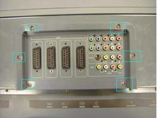

- Remove 20 screws securing the I/O bracket.
- Remove the bracket.


REMOVING DOWN COVER.
- Remove 5 screws securing the down cover.
- Remove 4 nuts securing the down cover.


- Push down cover a little bit backward.
- Remove the down cover as shown.


- Remove 20 screws securing back cover.

- Lift the back cover up.

- Remove the 2 screws securing the left speaker board.
- Remove the 2 screws securing the right speaker board.
- Disconnect the right speaker connector from the back cover.

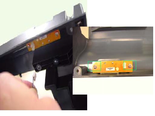
- Remove back cover as shown.

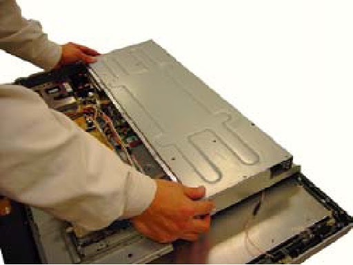
REMOVING TOP SHIELDING
- Remove the screws securing the top shielding.

- Push the top shielding a little bit upward.
- Remove the shielding.

REMOVING THE DMA BOARD.
- Disconnect the following connectors and antennas.

- Remove 6 screws securing the DMA board, and remove it.


REMOVING POWER BOARD
- Disconnect the connectors from the Power Board.

- Remove 9 screws securing the Power Board and the Remote Power Board.


REMOVING CONVERTER BOARD
- Disconnect connectors from the converter board.

- Remove 4 screws securing the converter board.
- Remove the converter board.


REMOVING AUDIO BOARD
- Disconnect cables from audio board.

- Remove 4 screws securing audio board.
- Remove audio board.


REMOVING THE I/O BOARD AND A-TUNER BOARD.


- Disconnect the connectors from I/O board.
- Remove 4 screws securing I/O board, and 4 screws securing the A-Tuner board.


- Remove the I/O board and A-Tuner board.
- Separate the I/o board and A-Tuner board.


REMOVING THE HEAT SINK
- Remove the 4 screws securing the heat sink.
- Remove the heat sink from main unit.


REMOVING THE ETHERNET BOARD
- Remove 2 screws securing the Ethernet board.
- Remove the Ethernet board.


- Disconnect the cable from Ethernet board.

- Remove 2 screws securing the Ethernet bracket and remove the bracket.


REMOVING THE D-TUNER
- Remove 3 screws securing the D-Tuner.
- Remove the D-Tuner.


REMOVING THE M/B & D-TUNER BOARD
- Disconnect cables from Main baord and D-Tuner.
- Remove 4 nuts and 2 screws securing the Main board.


- Remove the 2 screw, 3 short nuts and 4 long nuts securing D-tuner board.

- Remove the Main Board and D-tuner board.

- Separate the Main Board & D-tuner board.

REMOVING THE CARD READER MODULE
- Remove 3 screws securing the card reader module.
- Remove 2 screws securing the ground wire.

- Turn the card reader module over and disconnect the cables from card reader module.

- Disconnect the cables from AV3 board.

- Remove the 2 screws securing the AV3 board and remove it from card reader module.

REMOVING THE BEZEL SKIRT
- Remove 6 screws securing the bezel skirt.

- Remove bezel skirt.

REMOVING THE IR BOARD, POWER BUTTON AND KEYPAD BOARD.
- Remove the 2 screws securing the keypad board and remove it.

- Remove the two screws securing IR board, and remove 2 screws securing the Power button board.

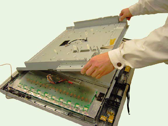
REMOVING PCB CHASSIS
- Disconnect cables from LVDS board.
- Remove 7 screws on the chassis bottom view.


- Remove 10 screws on chassis top view.

- Remove the PCD chassis as shown.
REMOVING ANTENNA
- Open the clip to release the antenna.

- Remove antenna.

REMOVING LCD PANEL
- Remove the 2 screws on the right.

- Remove the 2 screws on the left

- Remove the LCD panel

- remove 2 screws securing the right side bracket.
- Remove 4 screws securing the down bracket.

- Remove the right side bracket.

- Remove the down bracket.
- Repeat the same steps for left side and top bracket.
