 BELSON BSV4251 BSV4251A SERVICE MODE AND TROUBLESHOOTING

TO ENTER SERVICE MODE
- Switch ON the TV.
- When there is No OSD on screen,
- Press { MIX > CANCEL > HOLD > REVEAL } Buttons in sequence by the remote control.
- The period of 'two' press should be less than '3' seconds.
- To "EXIT", press 'TV' button.
OUT FACTORY STATUS
Contrast
|
45
|
Comb filter
|
ON
|
Brightness
|
28
|
Blue back
|
ON
|
Color
|
40
|
Black stretch
|
ON
|
Sharpness
|
35
|
SVM
|
ON
|
Treble
|
31
|
AVL
|
OFF
|
Bass
|
31
|
Surround
|
OFF
|
Balance
|
0
|
Page/button
|
Item
|
Meaning
|
Reference value
|
Remark
|
1
|
5PAR
|
HORIZONTAL PARABOLA
|
0-63
|
|
5HBOW
|
HORIZONTAL BOW
|
0-63
|
||
5HSH
|
HORIZONTAL SHIFT
|
0-63
|
FOR 50Hz
|
|
5EWW
|
EW WIDTH
|
|||
5EWP
|
EW PARABOLA
|
0-63
|
||
5UCR
|
EW UPPER CORNER PARABOLA
|
0-63
|
||
5LCR
|
EW LOWER CORNER PARABOLA
|
0-63
|
||
2
|
5EWT
|
EW TRAPEZIUM
|
0-63
|
|
5VSL
|
VERTICAL SLOPE
|
0-63
|
||
5VAM
|
VERTICAL AMPLITUEDE
|
0-63
|
||
5SCL
|
S-CORRECTION
|
0-63
|
||
5VSH
|
VERTICAL SHIFT
|
0-63
|
||
5VOF
|
TEXT POSITION VERTICAL OFFSET
|
41
|
||
1
|
6PAR
|
HORIZONTAL PARABOLA
|
0-63
|
|
6BOW
|
HORIZONTAL BOW
|
0-63
|
||
6HSH
|
HORIZONTAL SHIFT
|
0-63
|
||
6EWW
|
EW WIDTH
|
0-63
|
||
6EWP
|
EW PARABOLA
|
0-63
|
FOR 60Hz
|
|
6UCR
|
EW UPPER CORNER PARABOLA
|
0-63
|
||
6LCR
|
EW LOWER CORNER PARABOLA
|
0-63
|
||
2
|
6EWT
|
EW TRAPEZIUM
|
0-63
|
|
6VSL
|
VERTICAL SLOPE
|
0-63
|
||
6VAM
|
VERTICAL AMPLITUDE
|
0-63
|
||
6SCL
|
S-CORRECTION
|
0-63
|
||
6VSH
|
VERTICAL SHIFT
|
0-63
|
||
6VOF
|
TEXT POSITION VERTICAL OFFSET
|
28
|
||
VX
|
VERTICAL SOOM
|
25
|
||
RED
|
BLACK LEVEL OFFSET RED
|
32
|
||
GRN
|
BLACK LEVEL OFFSET GREEN
|
32
|
||
3
|
WPR
|
WHITE POINT R
|
0-63
|
ADJUST AROUND ‘31’
|
WPG
|
WHITE POINT G
|
0-63
|
||
BLUE
|
WPB
|
WHITE POINT B
|
0-63
|
|
3
|
YDFP
|
Y-DELAY FOR PAL
|
0-15
|
Brightness, color in accordance. For model with SVM function, SVN edge should be in symmetrical.
|
YDFN
|
Y-DELAY FOR NTSC
|
0-15
|
||
YDFS
|
Y-DELAY FOR SECAM
|
0-15
|
||
YDAV
|
Y-DELAY FOR AV
|
4
|
TOP
|
AGC TAKE OVER POINT
|
0-63
|
|
VOL
|
VOLUME
|
45
|
||
9874
|
GAIN CONTROL FOR TDS9874
|
20
|
||
IFFS
|
VISION IF
|
2
|
2-38.9, 3-38M
|
|
HDOL
|
CATHODE DRIVE LEVEL
|
8
|
||
AGC
|
IF AGC SPEED
|
1
|
||
AG2B
|
VG2 BRIGHTNESS
|
33
|
BEFORE ADJUST AG2, FIX IT.
|
|
5
|
OP1
|
OPTION BYTE 1
|
218
|
11011010
|
OP 2
|
OPTION BYTE 2
|
33
|
00100001
|
|
OP 3
|
OPTION BYTE 3
|
123
|
01111011
|
|
OP 4
|
OPTION BYTE 4
|
251
|
11111011
|
|
OP 5
|
OPTION BYTE 5
|
63
|
00111111
|
|
6
|
INT
|
INTIAL EEPROM
|
According to actual need initial EEPROM
|
|
7
|
LOGO
|
Logo 0
|
According to actual need set the logo
|
|
8
|
STS
|
STATUS
|
||
9
|
AGIN
|
AGING [ESCAPE BY LOCAL MENU]
|
Press Menu button on the set to Exit.
|
|
0
|
VG2
|
ADJUST VG2
|
In high / Out Low or line disappear.
|
CHECKING FOR NO PICTURE
- Check whether the CTRL B/D LED [D1 ~ D4] is turned ON or not.
- Check the power and signal cable of CTRL B/D.
- X B/D, Y B/D, Z B/D is well plugged in.
- Check the connection of X B/D, Y B/D & Z B/D to CTRL B/D
- Check the SCAN [Y side] IC
- Check the DATA [X side] COF IC {COF = Chip On Film}
- Replace the CTRL B/D.
DIAGNOSIS FOLLOWING DISPLAY CONDITION
- Confirm that the Power Connector of X B/D is well plugged in which is correspond to not showing screen.
- Confirm the connector that is connected between CTRL B/D and X B/D correspond not showing part.
- Replace relevant X B/D.
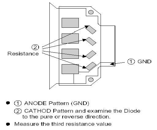
SCREEN DISPLAY FORM

- The problem between DATA COF and X B/D is more possible that the screen is not be shown as data COF.
- Confirm connector of Data COF is well connected to X B/D. Correspond to the part that screen is not showing.
- Confirm whether the Data COF is failed and replace X B/D.
EXAMPLE OF SCREEN DISPLAY {Anything of the '7' Data COF can be shown beside below illustrations]

DATA COF:
GENERATES UNUSUAL PATTERN OF DATA 'COF' IC UNIT.
- In case of generating unusual pattern of Data COF IC unit as picture given below, there is problem in the check that is input to Data COF IC.
- In case of (case1,2,3): Confirm the connection of Data COF connector. Replace the relevant X B/D.
- In case of (case 4&5): Confirm the connector that is connected from CTRL to X B/D. Replace the relevant X B/D or CTRL B/D.

- REGULAR STRIPE IS GENERATED ABOUT THE QUANTITY OF ONE DATA 'COF' IC OR MORE
- In case of generating regular stripe about the quantity of the Data COF IC, there is problem at the output of the output flatworm of X B/D. In case of generating regular stripe about the quantity of two Data COF IC, that means the data which is conveyed from CTRL B/D doesn't conveyed well.
- Confirm the XB/D connection connector plugged in well - correspond to unusual screen.
- Replace relevant XB/D or CTRL B/D.
SCREEN DISPLAY FORM

THE SCREEN DISPLAY HAS A PROBLEM FOR SCAN FFC.
- It bay be a problem between Scan FFC and Y B/D.
- Check the connection of Y B/D and Scan COF.
- If the Scan IC is failed, replace Y DRV B/D.
SCREEN DISPLAY FORM

Check a method or SCAN IC.

THE SCREEN HAS VERTICAL LINE WITH REGULAR GAP. A VERTICAL STRIPE FLASH AT ESPECIAL COLOR.
- This is a problem about control B/D.
- Replace Control B/D.
SCREEN DISPLAY FORM

A DATA COPY IS HAPPENED INTO VERTICAL DIRECTION
- In this case, it's due to incorrect marking of the scan wave.
- Replace a Y DRV B/D or a Y SUS B/D
Display form.

- THE SCREEN HAS SEVERAL VERTICAL LINES
In this case its not a problem about controller B/D or X B/D. It may cause the following.
- An out of order Panel.
- Open or Short Data COF FPC attached panel.
- Out of order a DATA COF attached panel.
Screen display form:

THE SCREEN DISPLAYS INPUT SIGNAL PATTERN, BUT THE BRIGHTNESS IS DARK
- Z B/D operation is not complete.
- Check the Power Cord of Z B/D.
- Check the connector of Z B/D and controller B/D.
- Replace the controller B/D or Z B/D.
THE SCREEN DISPLAYS OTHER COLOR PARTIALLY ON FULL WHITE SCREEN OF HAPPENS DISCHARGE PARTIALLY ON FULL BLACK SCREEN.
- Check the Declination of Y B/D setup, set down wave.
- Check the declination of Z B/D << ramp wave.
- Measure each output wave with oscilloscope [more than 200HHz] and compare the data.

CENTER OF THE SCREEN IS DARKER THAN THE EDGE OF THE SCREEN AT FULL WHITE PATTERN.
- It's is a problem about Z B/D ramp wave.
- Check the connection cable of Z B/D & CTRL B/D.
- Replace Z B/D.
DOES NOT DISPLAY A SPECIFIED BRIGHTNESS AT SPECIFIED COLOR
- Check the connector of CTRL B/D input signal.
- Replace the CTRL B/D.
POWER SUPPLY UNIT: PSU DGK-420W. Top View.

POWER SUPPLY UNIT: foil side.

TO ENTER SERVICE MODE
- PDP TV Power i On +/- -> Input select key on Remote control.
- Choose composite first and then PDP TV Power i Offi+/-.
- PDP TV Power iOffi+/- & INFO on the remote control => Erase => Enter.

PSU POWER SEQUENCE


