 Bose 3•2•1 and 3•2•1GS Series II –DVD lock DVD Lock Bypass and more…

Password setting – Parental control setting – DVD Unlock procedure - lock option – Computer set-up procedure and more....
Series
II System Date of Manufacture Information
Console - The product label for the console is located on the bottom of the unit. The date of manufacture is embedded in the serial number on the label. The following is an example:
Serial No. 035666941400014AZ
You will notice that there are four numbers underlined. This is the date of manufacture (DOM). The way it is read is that the first digit underlined represents the year of manufacture. The 4 indicates 2004.
The next three digits are the Julian date for the day of the year. In this example, that would be the 140th day of the year.
Bass
Module
The date of manufacture information is embedded into the product
serial number in the same format as is used for the console. The product label
for the bass module is located on the rear of the cabinet.
The date of manufacture is embedded in the serial number on the label. The following is an example:
Serial No. 034125941420677AS
You will notice that there are four numbers underlined. This is the date of manufacture (DOM). The way it is read is that the first digit underlined represents the year of manufacture. The 4 indicates 2004. The next three digits are the Julian date for the day of the year. In this example, that would be the 142nd day of the year.
DVD Lock Bypass
If a customer forgets his DVD Lock password,
or if you have a system in for repair that is locked and will not let
you play a DVD without a password, you can bypass the DVD Lock feature
by following the steps below.
1. Select a non-DVD source and press the SYSTEM button on the remote.
2. Navigate to the “DVD Lock” icon on the far right of the TV screen and press ENTER.
3. The system will then request the user to enter a password. On the remote control, punch in the bypass code, which is 2673. This is a backdoor password for entering this menu only, not for allowing discs to play.
4. After the bypass password is entered, you will be able to change settings in the “DVD Lock” menu.
5.
If you want to be able to play discs of all ratings, select OFF for
“Lock Unrated Discs” and “8” for “Lock Discs Rated Above.” This will
allow for all discs to play.
6.
If you wish to have the parental control engaged, refer to the table on
the previous page for ratings restriction definitions and options.
Setting a password and restriction level
Your
password will help prevent unauthorized viewing of DVD videos that have
a higher rating than your restriction level. There are 8 levels to
choose from, matched to movie ratings set by the Motion Picture
Association of America (MPAA).
1. Turn on your TV and select the correct TV input to view your 3•2•1 system.
2. Press the System button on your 3•2•1 remote control.
3. Using the right > and left < arrow buttons, highlight the DVD Lock option.
4. Press Enter or the down arrow key V.
Note: If you are using the DVD Lock option for the first time, enter a four-digit password. Then enter it again to confirm.
5. Enter your four-digit password.
6. Using the down V button, scroll down to Lock Discs Rated Above.
7. Press the right arrow > button to see the available settings.
8. Press the up arrow /\ or down arrow V button to find the rating you want.
9. Press Enter or the left arrow < button to save the setting.
10. Press Exit to dismiss the Settings menu.
Parental Control Setting - MPAA Rating - Audience Restriction – computer set-up procedure
8 None
7 NC-17 Adult audiences
6 R Mature audiences
5 Mature teenage audiences
4 PG-13 Teenage audiences
3 PG Mature young audiences
2 Most audiences
1 G General
DVD
Lock options
The DVD Lock options allow you to restrict viewing of DVD videos with certain ratings. To activate this feature, you need to set a level of restriction and establish a password in the DVD Lock section of the System menu.
The DVD Lock options allow you to restrict viewing of DVD videos with certain ratings. To activate this feature, you need to set a level of restriction and establish a password in the DVD Lock section of the System menu.
System
Option > Settings > Description
Lock
Unrated Discs Off On > No restriction applies to unrated DVD movies.
Restricts viewing access to unrated titles when password is set.
Lock Discs Rated 1 to 8 > Helps prevent viewing discs above the selected number when a password is created.
Change Password - - - - Establishes a new four number code to restrict access to movies with certain ratings.
Lock Discs Rated 1 to 8 > Helps prevent viewing discs above the selected number when a password is created.
Change Password - - - - Establishes a new four number code to restrict access to movies with certain ratings.
Premium (GSX) Console System Information
The
following information will only be displayed on the GSX console. The
standard console will not show this information as it does not have the
hard disc drive or the ethernet port.
Hard
Disc Drive Information: Press the ON/OFF button again. You should see
the hard disc drive information, similar to HARD DRIVE: KA100A TOSHIBA
MK4025GAS.
Hard
Disc Drive Self Test: Press the ON/OFF button again. You should see the
hard disc drive self test results, similar to HARD DRIVE SELF TEST: 00
00 00 10e5 0033r.
Gracenote
Database Information: Press the ON/OFF button again. You should see the
currently installed version of the Gracenotes database, similar to
GRACENOTE DATABASE: HDD...DB: 01.01.03.
Ethernet
Address Information: Press the ON/OFF button again. You should see the
current ethernet address information, similar to ETHERNET ADDRESS:
000C8A008BCE.
Computer
Setup Procedure
Use
this procedure to set up your IBM compatible PC for communication with the
3•2•1 system console.
1. Open
a terminal window, in either Terminal or
Hyperterm, as applicable for the version of Microsoft Windows you are using on
your PC.
2.
In the terminal window, click on FILE, then PROPERTIES. Set the properties in
the dialog box.

3.
In the properties dialog box shown in step 2, click on CONFIGURE to set the
COM1 Properties Click OK to return to the properties dialog box.
Bits
per second > 19200
Data
bits > 8
Parity
> None
Stop
bits > 1
Flow
control > None
4.
In the properties dialog box, click on the SETTINGS tab and set the controls as
shown.
[Be
sure to check "Play sound when connecting or disconnecting". 2. The examples shown on the following pages
are for Hyperterminal as used with Windows 2000 Professional. Your dialog box
views may vary slightly depending on the version of Windows and Hyperterminal
you have.]

5.
In the properties dialog box under the SETTINGS tab, click on the ASCII
Setup button and set the controls to look like the example at right.
Note: Be sure to click the “Send line ends with line feeds” box as
shown. If you fail to check this box, the 321 II console will not
communicate with the computer. Click OK to return to the properties
dialog box.

6.
Once you have made all of the settings in the properties dialog box,
click FILE/SAVE to save your setting. Click OK to close the window. You
have now configured your PC to communicate with the 3•2•1 Series II
system console. To connect to the console under test, in the terminal
window, click on CALL, then CALL and listen for the sound. This will
tell you that the PC is connected to communicate with the console. When
you have completed your session, click on CALL, then DISCONNECT to end
communication with the console.
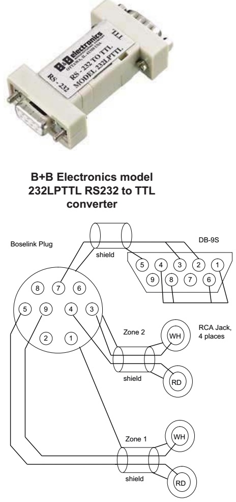
ETAP Cable Construction and Setup
You
will need to make up an ETAP cable using the diagram below. You can
build this cable from a Boselink A or B cable and a DB9 connector. You
don't need the RCA connectors if you don't want them. They are the Zone 1
and
Zone 2 audio inputs for the console. You will also need to use the same
level shifter you use for the 321 Series I for TAP. This level shifter
made by B+B Electronics, model number 232LPTTL, and can be purchased
online at http://www.bb-elec.com. Refer to the photo at right for an
image of the converter.
ETAP Overview
A
serial RS-232 interface is provided on the console for communicating
with the test system. This interface, called ETAP (Extended Test Access
Port), and it uses strings of standard ASCII characters as commands.
The ETAP is accessed
via the expansion port (BoseLink) interface. Some of the commands will
be brokered by the Main Board through to the Tuner Board for
implementation, and the subsequent replies will be generated by the
Tuner Board and passed via the Main Board out to the test system.
Boselink ETAP Cable Wiring Diagram
Terminal Parameters
Using
an IBM compatible PC with Microsoft Windows, Open a hyperterminal
window. Set up the session to communicate with the console using 19200
baud, 8 data bits, no parity, one stop bit.
Setting up console for ETAP mode
Immediately
after system bootup (within 5 seconds) an ETAP command must be issued
to put the console into ETAP mode. Any ETAP command can be used to set
this. Note: The system must have power removed, and then re-applied in
order for it to boot. Pressing the ON-OFF button on the console does not
completely remove power. The Boselink input and ETAP port share the
same hardware UART on the CS98200 and it must know which format to speak
via the Boselink connector. If no ETAP command is issued in this time,
then the console assumes that the unit is operating in a “customer
environment” and switches to Smart Speaker.