 FISHER & PAYKEL_SMARTDRIVE ELECTRONIC WASHING MACHINE_PHASE 1 TO 5 - 230V _ OTHER CHECKS _ SHAFT AND BEARING REMOVAL _ REASSEMBLY _ TROUBLESHOOTING FLOWCHART

FISHER & PAYKEL_SMARTDRIVE ELECTRONIC WASHING MACHINE_PHASE 1 TO 5 - 230V _ ASSEMBLY GUIDELINES _MOTOR DISASSEMBLY AND REASSEMBLY
FISHER and PAYKEL_SMARTDRIVE ELECTRONIC WASHING MACHINE_PHASE 1 TO 5 - 230V _DISASSEMBLE PROCEDURE
- Isolate from the power supply.
- To remove the lid, open it to the upright position and lift it clear.
- Remove the 2 screws from the rear of the top console, disconnect the earth lead. The console can now be raised for access to the Motor Controller Module, Display Module and associated wiring.
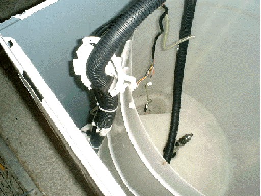
- PHASE-5 TOP DECK SHOWING WIRING CONNECTIONS

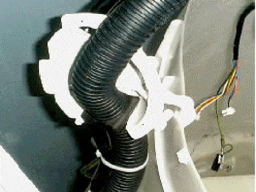
- PHASE-2 TOP DECK

- Disconnect the pressure tube from the pressure sensor.
- Disconnect display module plug, the motor/pump harness plug and Rotor Position Sensor plug. Remove the pump earth lead and mains cable earth lead from the Motor Controller Module. Remove the plugs from the back of the mains cable clamp, undo the 2 screws holding the clamp and remove the clamp from the console feed the mains cable earth wire through the cable clamp opening.
NB: DON’T REMOVE THE EARTH CONNECTION FROM THE
WRAPPER
- Remove the two rubber buffers and screws from the front of the top deck. Release the retaining clips at rear of cabinet using a flat bladed screwdriver. Lift the top deck clear, feeding wiring through hole in top deck corner of the cabinet.
NB: The
top deck cannot be hinged back without first releasing the rear clips from the
cabinet and lifting at the same time.

- Unclip the bias spring from the front left suspension rod. Unclip the neck ring from the top of the outer bowl.
- Remove the fabric softener dispenser, unscrew the agitator retaining nut and remove the agitator.
- The inner bowl may now be lifted clear. (If the inner bowl is not easy to lift clear, then remove the three spline retaining screws and remove the driven spline. Then pull the drive spline off the shaft and lift out the inner bowl).
- If not already removed, the clutch can be disassembled at this stage by removing the three screws from the driven spline.


- Remove the screw from the drain hose outlet bracket on the rear of the wrapper.
- Unclip the harness duct from the right hand rear suspension and remove the suspension assembly by lifting the corner bracket upwards, and free the suspension assembly from the outer bowl.
- Feed the drain hose inside the wrapper. Clip the drain hose fixture over the outer bowl with the attached hook.
- Remove the remaining three suspension rod assemblies
- Lay the cabinet on its back, on protective material, and slide the outer bowl assembly out, but note that approximately 1 litre of water must be removed from the pump sump before laying the cabinet on its back.


- To remove the pump, release the locking tab. Turn the pump anti-clockwise, lift it clear and remove the electrical connections.
- Remove the two screws securing the wiring duct to the outer bowl base.
- Remove the drain hose clamp. Twist the drain hose in an anti-clockwise direction to release the bayonet fitting. If changing the outer bowl, the pump securing plate can be removed at this stage by unscrewing the 4 x3/8" securing bolts.
- Remove the clamp from the pressure tube and pull the tube off the spigot on the pressure chamber.
- Unclip the pump harness and then remove the complete assembly.

Assembly
is the reverse of disassembly. The following points are worth noting.
- Drain Hose Outlet Elbow. Refit to the base. NB: Ensure the lugs on the elbow are located underneath the pump bracket. Clamp into position.
- Pump. Turn the pump clockwise when refitting it into the bayonet fixture. Check that the locking tab has clicked into place.
- Wiring. Fit the wiring harness into all the securing clips. Check that the harness assembly is secured to the suspension rod.

- Drain Hose. Unclip the drain hose fixture from the lip of the outer bowl and screw into position on the cabinet. Ensure the drain hose grommet is correctly fitted.
- Topdeck. Before refitting topdeck ensure that reed switch harness (phase 2-5) is tightly secured. When refitting top deck ensure that OOB lever does not catch or sit on neck ring.
- Base panel: Ensure locating tags are straight before refitting.
- Pressure Hose. CHECK THAT THE LOOM AND PRESSURE TUBE ARE NOT KINKED or close to wrapper before refitting the top deck. Blow down the pressure tube to check if it is clear of water droplets. Ensure that the nylon cord in the pressure tube does not obstruct when reconnecting tube.
- Mixing Chamber. Phase 5 only. Ensure that thermistor or plug is correctly located.
- Safety testing should be carried out in accordance with standard electrical testing procedures. The resistance from the earth contact on the mains lead to the wrapper should not exceed 0.5 ohms. The insulation resistance should also be measured at 500 volts DC between phase & neutral to earth. The maximum resistance should not exceed 1Mohm.
Test
Smartdrive by filling (using both valves), draining and spinning to 1000
RPM. Open lid when at 1000 RPM. Check the size and the operation of the Out
of Balance lever.

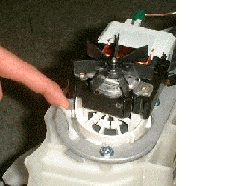
MOTOR ASSEMBLY AND DISASSEMBLY
- Remove the rotor by using a 16mm or 5/8" socket. Lift the rotor clear, and place in a plastic bag. The rotor has strong magnets and can attract metal objects. If any foreign objects are caught in the rotor area these may cause the magnets to wear and create a fine black powder which will permeate through the whole appliance.
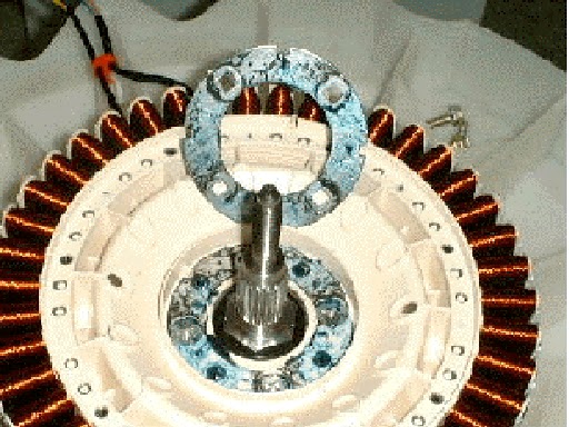
- Unscrew the 4 bolts securing the stator to the outer bowl using a 3/8" socket.
- Lift the stator clear of the shaft, turn over.

ASSEMBLY
- Wire up stator before locating stator into position. CHECK Red Blue & yellow wiring is correct.
- Grease the stator side of the clamp plates and the inside section of the stator that fits over the bearing. Fit the clamp plate and spacer assembly to the back of the stator. Locate the stator into position. It will only fit in one position.
- Refit the clamp plate onto the stator and tighten the four 3/8" bolts to a torque of 5 Nm.
NB:
The stator should have a slight radial movement of approximately 0.5 - 1mm when
correctly tightened and should have maximum axial play (rocking movement) of
0.5mm.
- Fit the wiring harness into the securing clips.
- Fit the rotor onto the shaft and locate on the spline. Using a 16mm socket, tighten the plastic nut to a torque of 16 Nm. Hold the rotor stationary until it is secured.

PUMP BLOCKAGE
- Pump Block error is fault code 37. This is one of the most likely problems encountered in Smartdrive. See section 11.0 for more information on fault code 37.
- Drain the Bowl. This can either be done using the pump or emptying the bowl manually.
- If there is a service hatch (Phase 1-4). Remove the front inspection panel by inserting a screw driver into the slot and turn anticlockwise 1/8 of a turn. Pull outwards and remove.
- Flick Starting the pump. Advance to SPIN and attempt to flick start the fan on the pump motor. This may alleviate the need to drain manually.
- Draining Manually. Disassemble top deck, neck ring, agitator and inner bowl. Use a container to empty the bowl.
- Check for foreign object by inspecting from above. Removing pump hood, cap and impeller. Check for obstructed drain hose.

OTHER CHECKS
- Check pump hood, cap and impeller are the latest type.
- If the product is 5kg size check that a rain shield is fitted to the pump p.n. 426292.
- Check that the four bolts securing the pump bracket are tight, torque 3 Nm.
- If the screw locating the pump hood is loose, torque 3 Nm, this can cause pump block error.
To
remove the pump, turn it towards the front of Smartdrive until the locking tab
prevents further turning, then release the locking tab by pulling it away from
the pump. Continue to turn, the pump will disengage. When refitting the pump,
making sure that the bayonet fixture is located correctly. Twist the pump away
from the front of Smartdrive until the locking tab clicks into place.
NB:
Approximately 1 litre of water remains in the pump sump after pump out and can
spill out when the pump is removed. However
by tilting Smartdrive past 45 degrees and blowing down the drain hose this can
be alleviated.
- There is 230V AC at the pump terminals the whole time Smartdrive is switched on at the power point.

SHAFT AND BARING REMOVAL
- Fit the spline tool over the shaft. Remove the 1 1/4"AF shaft retaining nut securing the shaft.
- Lay the outer bowl on its side before removal of the shaft. This ensures that the shaft does not fall directly onto the floor.
NB:
The shaft can only be removed towards the inside of the outer bowl. Remove
the shaft. If the shaft is difficult to remove, use a puller and a mandrel.
Refit the thick stator motor clamp plate onto the outer bowl and secure with
the four stator mounting bolts. The stator clamp plate may be used to hold the
legs of the puller in place.
WARNING:
Make sure the stator clamp plate is flat before using. If in doubt, replace.
- Remove the outer bearing using the bearing removal tool.
WARNING:
Do not remove the bearings with a hammer and drift as serious damage to the
bearing housing or outer bowl may result. Use the bearing removal tool as
illustrated:

- Remove the seal with the aid of a screwdriver handle levering from side to side.
- Remove inner bearing using the bearing removal tool. Insert the threaded rod and extractor washer up from the bottom of the outer bowl. Place the collar and large locating spigot on the threaded rod and extract the bearing.
SHAFT AND BARING ASSEMBLEY
- The bearings must be inserted separately with the inner bearing fitted first and pulled down with the bearing tool onto the shoulder in the bearing housing. IMPORTANT: There must be no gap between the bearing outer race and the shoulder of the aluminum extrusion. Remove the insertion tool at this point and check that the inner bearing is fully home.
- Fit the bearing spacer and press in the outer bearing using the bearing tool. Check the spacer has no end float but has slight sideways movement to allow for shaft insertion.
- Ease the shaft through the bearings from inside the outer bowl. Take care the shaft is fitted with the threaded retaining nut section facing downwards in the direction of the base.
- Fit the shaft retention nut. Use the spline tool and spanner to tighten the shaft retention nut.
- Invert the outer bowl. Take care not to damage the shaft or flooring. Fit the assembly thimble sleeve onto the shaft before fitting the seal. Lubricate the seal outside diameter with liquid detergent and then slide into position by pressing down on both sides of the seal.
NB:
The seal should be flush with the lip on the base of the outer bowl.

TROUBLESHOOTING FLOWCHART
- This is a flow chart for original Phase 1 Smartdrive Motor Controllers and Displays. These are fitted with a slow blow 32mm 6A fuse. Use this flow chart when there is no power to the display module and Smartdrive is powered on.

Click on image. Right click on the enlarged image, save image as, to a folder (My document > My Pictures).