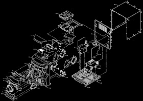
Philips FWM3000 Mini Hi-Fi system - Disassemble procedure, schematic diagram
Philips Seu Mini Hi-Fi System - FWM3000, FWM3500, FWM4000, FWM4500 - Disassemble procedure, Circuit diagram - Exploded view
Disassembly [Click on the pictures to magnify]
1) Remove 9 screws A and 6 screws B/C as indicated to loosen the outer plate.2) Remove 3 screws D as indicated to loosen the outer plate.
1)
Remove 2 screws E and 2 screws F as indicated to loosen the CD part.
2) Remove 2 screws G as indicated to loosen the Bottom Plate.
3) Remove 4 screws H and 2 screws I as indicated to loosen the Rectifier Board.
4) Remove 3 screws K and J as indicated to loosen the Main Board
2) Remove 2 screws G as indicated to loosen the Bottom Plate.
3) Remove 4 screws H and 2 screws I as indicated to loosen the Rectifier Board.
4) Remove 3 screws K and J as indicated to loosen the Main Board
5)
Remove 3 screws L as indicated to loosen the Tuner Board
6)
Remove 4 screws M as indicated to loosen the Amp Board
7)
Remove screws N as indicated to loosen the Display Board and Key mic Board.
CD board schematic
MCU board schematic
Power amplifier board schematic
Used
ICs: BU9543 – AM5888S – TA7291 – BX8805 – M12L16161A00 – WM8782EDS – TDA8922CTH (Power
Amp)


