 Technical description and composition of the SAMSUNG UE32D5500 TV, panel type and applicable modules. The composition of the modules.
SAMSUNG LED
Model: UE32D5500 RW
Chassis / Version: U66A / Ver: CN01
Panel: LD320BGC-C1
T-CON: V460HJ1-C01 CG24-CG11 RG24-RG11 GMA_18-GMA_1
LED driver (backlight): integrated into PSU; 148V, 290 mA
PWM LED driver: SEM5025
MOSFET LED driver: MDD5N40
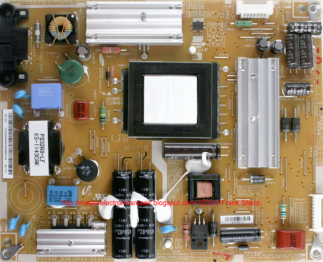
Power Supply (PSU): BN44-00460A
PWM Power: FAN7602C
MOSFET Power: MDF13N6B
MainBoard: BN41-01660A
IC MainBoard: CPU: WT61P805 (Standby) and SEMS21 1108A-LF, NAND: K9GAG08U0E (1981 1010.0 A), NAND BGA: KFG1GN6W2D (1990 1010.0 B), DDR: D9LGQ, EEPROM: ATMLH108 2ECL, AUDIO: NTP
Tuner: BN40-00196A DT0S40FVH082A
Technical Specifications UE32D5500
SAMSUNG UE32D5500
General repair guidelines for TV LCD LED
In the case when the UE32D5500 does not turn on, does not respond to the remote control and buttons on the front panel, does not blink lights and does not show any signs of operability, the power supply module BN44-00460A is probably faulty in this case. In the absence of swollen filter capacitors of the secondary rectifiers, the diagnostics of the power supply should begin by checking the fuse and, if it is broken, it is first necessary to check all the power semiconductor elements of the primary circuit - diodes and transistors MDF13N6B, D4184, MDD3752 for the possibility of an avalanche or thermal breakdown.
Mos-Fet keys used in switching power supplies (SMPS) rarely fail for no reason to look for when checking other circuit elements. Often the breakdown is caused by malfunctions of electrolytic capacitors or semiconductor elements in the primary circuit, or by a break in the resistors in the stabilization circuits. The FAN7602C PWM controller chip can also cause a breakdown of the power switch of the converter.
Sometimes the SAMSUNG UE32D5500 TV does not have an image, but there is sound, or the image appears and immediately disappears. In this case, there is a possibility of a malfunction of the LED driver - the power converter of the backlight LEDs of the LD320BGC-C1 panel, or a break in the LED circuit is possible. In such cases, first of all, it is necessary to verify the operability of the electrolytic capacitors of the filter by the power of the backlight unit.
The lack of backlight often occurs due to an open circuit in the LED circuit. There is a need for disassembling the panel and checking the LEDs themselves, as well as the same contact connections in the connectors and rations of the terminals.
It is impossible to detect a break in the LED line without disassembling the panel with a simple multimeter. The LEDs are connected in series and to open their transitions, a voltage of several tens of volts is required. Ideally, a current source is suitable for such purposes. You can open the panel and check each LED separately. Usually, Chinese multimeters light up a single 3-volt LED, if you connect the probes in the forward direction to it (red probe to the anode, black to the cathode). In dual 6-volt LEDs, the PN junction of its emergency zener diode can serve as a health indicator. In the event of a LED malfunction, its zener diode will either be cut off or broken into short-circuit.
Repair of the motherboard BN41-01660 A must begin with the diagnosis and verification of all linear stabilizers and power converters of its microcircuits. Sometimes it may be necessary to update the software (software) - flashing FLASH or EEPROM.
Board repair and replacement of CPU chips: WT61P805 (Standby) and SEMS21 1108A-LF, NAND: K9GAG08U0E (1981 1010.0 A), NAND BGA: KFG1GN6W2D (1990 1010.0 B), DDR: D9LGQ, EEPROM: ATMLH108 2ECL AUDIO: are made in the presence of the necessary equipment, and the corresponding element base. Faults associated with the application of BGA processor soldering technologies can be localized by the heating method.
If a tuner BN40-00196A DT0S40FVH082A is suspected of malfunction, first of all, it is necessary to verify the correctness of the software, as well as the presence of the necessary power supply voltage levels and data exchange pulses with the processor via the I2C bus at the corresponding tuner pins.
It should be remembered! Attempts to repair the SAMSUNG UE32D5500 TV, in the absence of the necessary qualifications and experience, are categorically not recommended and are fraught with negative consequences, up to the complete non-repairability of the device!
SCHEMATIC MANUAL ---------------> Samsung UE32D5500 Chassis U66A.
Chassis : U66A Model : UE32D55**R*, UE37D55**R*, UE40D55**R*, UE46D55**R*, UE32D57**RS, UE37D57**RS, UE40D57**RS, UE46D57**RS
Chassis : U57A Model : UE32D50**PW, UE37D50**PW, UE40D50**PW, UE46D50**PW, UE32D40**NW
Chassis : U57B Model : UE19D40**NW, UE22D50**NW, UE27D50**NW
NAND BGA KFG1GN6W2D (1990 1010.0 B).
PSU SCHEMATIC -------------> BN44-00460A
 The appearance of the MainBoard BN41-01660A is shown in the figure below:
BN41-01660A
BN41-01660A can be used in TVs:
SAMSUNG UE40D5520RW (Panel LD400BGC-C1 DD01), SAMSUNG UE32D5500 RW (Panel LD320BGC-C1), SAMSUNG UE32D5520RW UE32D5520 (Panel LD320BGC-C1).
The appearance of the power supply
Main features of the SAMSUNG UE32D5500 device:
Installed matrix (LED-panel) LD320BGC-C1.
The matrix control uses the Timing Controller (T-CON) V460HJ1-C01.
To power the backlight LEDs, a converter is used, combined with the power supply, controlled by the SEM5025 PWM controller. As power elements of the LED driver, keys of the MDD5N40 type are used.
The necessary supply voltages for all nodes of the SAMSUNG UE32D5500 TV are generated by the BN44-00460A power module, or its analogs using FAN7602C microchips and MDF13N6B type power switches.
MainBoard - the main board (motherboard) is a BN41-01660A module, using CPU chips: WT61P805 (Standby) and SEMS21 1108A-LF, NAND: K9GAG08U0E (1981 1010.0 A), NAND BGA: KFG1GN6W2D (1990 1010.0 B), DDR : D9LGQ, EEPROM: ATMLH108 2ECL, AUDIO: NTP-7411S and others.
The tuner BN40-00196A DT0S40FVH082A provides the reception of television programs and tuning to channels.