Technical description and composition of the SAMSUNG UE32F6540 TV, panel type and applicable modules. The composition of the modules.
SAMSUNG LED
Model: UE32F6540
Chassis / Version: TU02
Panel: CY-HF320CSLV3V
T-CON: BN41-01939
LED driver (backlight): integrated into PSU
PWM LED driver: SLC2013M
MOSFET LED driver: KF9N25D
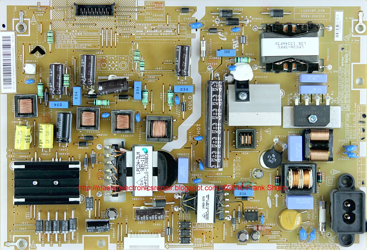
Power Supply (PSU): BN44-00620A
PWM Power: D2011K, S3050, 3110A
MOSFET Power: 13NM60N (PFC), 5R380CE
MainBoard: BN41-01958A BN94-06736S
IC MainBoard: K4B2G1646Q-BCMA x3, KLM4G1FE3B-B001, 25Q40CL, AT24C256C (2EC) WT61P807, TAS5745
Tuner: BN40-00258A
Technical Specifications UE32F6540
SAMSUNG UE32F6540
General repair guidelines for TV LCD LED
Possible malfunctions
- SAMSUNG UE32F6540 TV does not turn on at all. There is no reaction to the remote control and control buttons from the front panel. Indicator lights do not light or flash.
In such cases, the BN44-00620A power supply is usually faulty. It is necessary to measure its secondary output voltages, and if they are absent, check the power switches (13NM60N (PFC), 5R380CE) and rectifier diodes in the converters for a short circuit.
In case of any breakdown of semiconductors in the secondary circuits, the converter can usually work normally in emergency short circuit mode. There are no output voltages. And during short circuit in the power elements of the primary circuit, as a rule, the mains fuse breaks and less often the current sensor at the source of the key.
Mos-Fet power switches used in switching power supplies sometimes fail due to a malfunction of any other elements that can put it out of operation in key mode or create an excess of the maximum permissible key parameters. These can be elements supplying the PWM controller, frequency-setting or damping circuits, or negative feedback elements in the stabilization circuit. PWM controllers D2011K, S3050, 3110A, in the absence of visible damage or frank short-circuit between the terminals, are checked by replacing with new ones, or obviously working.
- There is no image, but there is sound and reaction to commands from the remote control. Or the image appears immediately after turning on and disappears.
Usually in such cases, a malfunction is detected in the backlight nodes of the LED panel. The reason for this may be a break in the LED circuit, or a problem in stabilizing their power supply.
To check the health in the LED circuit, it is better to use a current source with a maximum voltage of 200V. We do not recommend using any voltage sources for this purpose. You can test each LED individually with a simple Chinese multimeter (powered by 9 volts) in the P-N-junction test mode. If you connect the red probe of the multimeter to the anode of the LED, and the black to its cathode, then the 3-volt LED will light up slightly, and in the opposite direction you can detect the transition of the emergency zener diode. A zener diode PN junction indirectly indicates a LED-a
- The TV does not turn on, does not respond to the remote control. The indicator blinks or signals standby mode.
Repair or diagnostics of the BN41-01958A motherboard should begin by checking the stabilizers and power converters needed to power the chips and matrix. If necessary, you should update or replace the software (software). In some cases, to repair the MB board (SSB), it may be necessary to replace the chips - K4B2G1646Q-BCMA x3, KLM4G1FE3B-B001, 25Q40CL, AT24C256C (2EC) WT61P807, TAS5745 with new or obviously working ones. In cases where BGA technologies are used, defects are usually localized by the heating method.
Before changing the tuner BN40-00258A, if there is no possibility of tuning to television channels, you should make sure that there are supply voltages that must be measured at the corresponding terminals of the tuner and check the software for correctness. The pulses of the data exchange of the tuner with the processor can be controlled by an oscilloscope
Attention! Users and owners of UE32F6540 TVs who do not have the appropriate qualifications, knowledge and experience are strongly discouraged from attempting self-repair in order to avoid negative consequences that could lead to complete non-repairability of the device.
FIRMWARE FOR SPI FLASH, EEPROM --------------> SAMSUNG UE32F6540 TU02, Main: BN41-01958A BN94-06736S, Panel: CY-HF320CSLV3V
 The appearance of the MainBoard BN41-01958A is shown in the figure below:
BN41-01958A
BN41-01958A can be used in TVs:
SAMSUNG UE39F5500 UE39F5500AK (Panel HF390BGM-C1), SAMSUNG UE32F5300AK (Panel HF320BGA-B1), SAMSUNG UE32F6200 UE32F6200AK (Panel CY-HF320BGLV2V), SAMSUNG UE42F5500AK (Panel HF420BGA-B1), SAMSUNG UE32F4500AK (Panel HF32AGH-R1), SAMSUNG UE32F5500AK UE32F5500AW (Panel HF320BGA-B1), SAMSUNG UE40F6400 UE40F6400AK (Panel CY-HF400CSLV2V), SAMSUNG UE42F5300AK (Panel CY-HF420BGAV1V CY-HF460BGLV2V), SAMSUNG UE46F6400AK (Panel CY-HF460CSLV2V), SAMSUNG UE46F6540AB (Panel CY-GF460CSLV3V), SAMSUNG UE40F6540AB (Panel CY-GF400CSLV3V), SAMSUNG UE40F6650 UE40F6650AB (Panel CY-GF400CSLV1V), SAMSUNG UE32F6540 (Panel CY-HF320CSLV3V) , SAMSUNG UE46F5300 UE46F5300AK (Panel CY-HF460BGLV1V), SAMSUNG UE32F6800 UE32F6800AB (Panel CY-HF320CSLV1V).
The appearance of the power supply
Main features of the SAMSUNG UE32F6540 device:
Installed matrix (LED panel) CY-HF320CSLV3V.
The matrix control uses the Timing Controller (T-CON) BN41-01939.
To power the backlight LEDs, a converter is used, combined with the power supply, controlled by the SLC2013M PWM controller. As power elements of the LED driver, keys of the KF9N25D type are used.
The necessary supply voltages for all nodes of the SAMSUNG UE32F6540 TV are generated by the BN44-00620A power module or its analogs using D2011K, S3050, 3110A microcircuits and power switches of the 13NM60N (PFC), 5R380CE type.
MainBoard - the main board (motherboard) is a BN41-01958A module, using microchips K4B2G1646Q-BCMA x3, KLM4G1FE3B-B001, 25Q40CL, AT24C256C (2EC) WT61P807, TAS5745 and others.
The tuner BN40-00258A provides the reception of television programs and tuning to channels.