 Technical description and composition of the SAMSUNG UE40D6500 TV, panel type and applicable modules. The composition of the modules.
SAMSUNG LED
Model: UE40D6500 UE40D6500VS
Panel: LTJ400HV01-J
LED backlight: 3D_11Y400HFSL4LV0.2, 3D_11Y400HFSR4LV0.2
T-CON: SH120PMB4S V0.3 (LSJ400HV01-S)
LED driver (backlight): integrated into PSU
PWM LED driver: SEM5025
MOSFET LED driver: STU432S
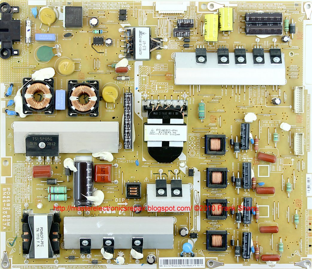
Power Supply (PSU): BN44-00427A PD46B2_BSM
PWM Power: SQD3011K, UCC25600, ICE2PCS06 (PFC)
MOSFET Power: MDF9N50, 10NM60N
MainBoard: BN41-01587E BN94-05105T
IC MainBoard: SDP1001, SDP1005, SDP94, SIL9489ACTU, K4B2G1646C-HCH9, EPM240T100C4N
Tuner: BN40-00217A
Technical Specifications UE40D6500
SAMSUNG UE40D6500
General repair guidelines for TV LCD LED
Possible manifestations of defects
- The SAMSUNG UE40D6500 TV does not turn on and does not show any signs of turning on, it does not respond to the control buttons or the remote control.
With similar manifestations, in some cases, the BN44-00427A power module is faulty. Then we recommend that you measure its output voltages and, if they are absent, you should check the health of the power switches (MDF9N50, 10NM60N) and rectifier diodes of the converters for possible short circuit.
In case of diode breakdowns in the secondary circuits, the converter can operate in emergency short-circuit mode without output voltages, and during short circuit in the power elements of the primary circuit, the mains fuse and / or current sensor at the source of the key usually breaks.
Mos-Fet power switches, used in switching power supplies, sometimes fail due to a malfunction of any other elements that can put it out of operation in key mode or create an excess of the maximum permissible parameters of the switch. These can be elements supplying the PWM controller, frequency-setting or damping circuits, or negative feedback elements in the stabilization circuit. PWM controllers SQD3011K, UCC25600, ICE2PCS06 (PFC), in the absence of visible damage or frank short-circuit between the terminals, are checked by replacing with new, or obviously working.
- There is no image, there is sound, it responds to the remote control. Or the image may appear for a second when turned on and immediately disappears.
The most likely in these cases is a malfunction of the LED backlight. The reason for this may be a break in the LED circuit, or a problem in stabilizing their power supply.
To detect a break in the LED lines without disassembling the panel, a current source is required. It is impossible to open transitions connected in series with a simple multimeter; voltage of several tens of volts is necessary.
- The TV does not turn on, does not respond to the remote control. The indicator blinks or signals standby mode.
Repair or diagnostics of the BN41-01587E motherboard should begin by checking the stabilizers and power converters needed to power the chips and matrix. If necessary, update or replace the software (software). Often, the MB (SSB) card must be replaced in case of complex malfunctions that are difficult to detect. When trying to repair, you should check its elements - SDP1001, SDP1005, SDP94, SIL9489ACTU, K4B2G1646C-HCH9, EPM240T100C4N and replace the failed chips with new ones. Some malfunctions may be due to the use of BGA soldering technologies in modern Main Board. Typically, such defects are detected by local heating of the chip.
The malfunction of the tuner BN40-00217A is established after checking the software and all the supply voltages at its terminals. The data exchange of the tuner with the processor via the I2C bus can be controlled by an oscilloscope.
Owners and users of the SAMSUNG UE40D6500 TV should remember that self-repair without special knowledge, skills and qualifications can be fraught with negative consequences that can lead to complete non-repairability of the device!

 The appearance of the MainBoard BN41-01587E is shown in the figure below:
BN41-01587E
BN41-01587E can be used in TVs:
SAMSUNG UE40D6510 UE40D6510WS (Panel LD400CSC-C2), SAMSUNG UE55D6100SW (Panel LTJ550HW04-L), SAMSUNG UE46D6530WS UE46D6530 (Panel LTJ460HW01-V), SAMSUNG 32D6510 32D6510WS (Panel LD320CSC-C2), SAMSUNG UE40D6530 UE40D6530WS (Panel LTJ400HV01-V), SAMSUNG UE46D6510WS UE46D6510 (Panel LTJ460HW02-L), SAMSUNG UE32D6510WS UE32D6510 (Panel LD320CSC-C2), SAMSUNG UE40D6500 UE40D6500VS (Panel LTJ400HV01-J).
The appearance of the power supply
Main features of the SAMSUNG UE40D6500 device:
Installed matrix (LED-panel) LTJ400HV01-J.
The matrix control uses the Timing Controller (T-CON) SH120PMB4S.
To power the backlight LEDs, a converter is used, combined with a power supply, controlled by the SEM5025 PWM controller. As power elements of the LED driver, keys of the STU432S type are used.
The necessary supply voltages for all nodes of the SAMSUNG UE40D6500 TV are generated by the BN44-00427A power supply module or its analogs using SQD3011K, UCC25600, ICE2PCS06 (PFC) microcircuits and power switches of the MDF9N50, 10NM60N type.
MainBoard - the main board (motherboard) is a module BN41-01587E, using microchips SDP1001, SDP1005, SDP94, SIL9489ACTU, K4B2G1646C-HCH9, EPM240T100C4N and others.
The tuner BN40-00217A provides the reception of television programs and tuning to channels.