 Technical description and composition of the SONY KDL-32RD433 TV, panel type and applicable modules. The composition of the modules.
SONY LED
Model: KDL-32RD433
Chassis / Version: BBE
Panel: IS6S320DNO01
LED backlight: SAMSUNG 2015SONY_TPZ32_FCOM_A05 REV1.0_151014
T-CON: HV320WHB-N5K 47-6001332
LED driver (backlight): integrated into MainBoard
PWM LED driver: BD9423EFV
Power Supply (PSU): Adapter 19.5V
MainBoard: 1-980-335-22 (173587122) A2093497D
IC MainBoard: MT5566BQVT
Tuner: DE243ZP
Control: IR: 1-980-483-21 (173594721)
Technical Specifications KDL-32RD433
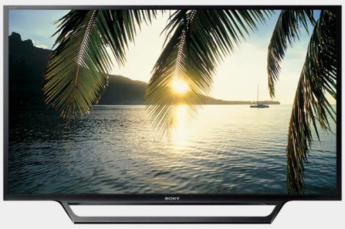
SONY KDL-32RD433
General repair guidelines for TV LCD LED
Possible malfunctions
- The SONY KDL-32RD433 TV does not turn on at all. There is no reaction to the remote control and control buttons from the front panel. Indicator lights do not light or flash.
With such manifestations, in some cases, the Adapter power module is faulty.
The owner of the TV can purchase an external power supply unit such as Adapter and repairing it is not always advisable. In any case, the simplest typical defects characteristic of most IIP schemes can be easily detected and eliminated after opening. It is necessary to verify the presence of its output voltages and, if they are completely absent, check the power switches and rectifier diodes for a probable short circuit.
In case of breakdowns in the secondary circuits, the converter can operate in a short circuit mode, and during a short circuit in the elements of the primary circuit, the mains fuse usually breaks.
Mos-Fet power switches, used in switching power supplies, sometimes fail due to a malfunction of any other elements that can put it out of operation in key mode or create an excess of the maximum permissible parameters of the switch. These can be elements supplying the PWM controller, frequency-setting or damping circuits, or negative feedback elements in the stabilization circuit. PWM controllers, in the absence of visible damage or frank short-circuit between the terminals, are checked by replacing with new, or obviously working.
- There is no image, there is sound, it is responding to the remote control. Or immediately after turning on for a second, the image may appear and immediately disappear.
In some of these cases, the malfunction is caused by a lack of backlighting on the display. The reason for this may be a break in the LED circuit, or a problem in stabilizing their power supply.
When diagnosing, it is necessary to take into account that it is impossible to check the open in the chain of LED lines without disassembling the panels using a tester or multimeter. To open all PN junctions connected in series, a voltage of the order of several tens of volts is required, and ideally, a current source. By opening the panel, each LED can be checked separately. Typically, Chinese multimeters light up a single 3-volt LED, if you connect probes in the forward direction to it. In dual 6-volt LEDs, the PN junction of its emergency zener diode can serve as an indicator of health. In the event of a LED malfunction, its zener diode will either be cut off or broken into short-circuit.
- The TV does not turn on, does not respond to the remote control. The indicator blinks or signals standby mode.
Repair or diagnostics of the motherboard 1-980-335-22 should begin by checking the stabilizers and power converters needed to power the microcircuit and matrix. If necessary, update or replace the software (software). Board repair and replacement of MT5566BQVT microcircuits are carried out with the necessary equipment, and the corresponding element base. Faults associated with the application of BGA processor soldering technologies can be localized by the heating method.
Before changing the tuner DE243ZP, if there is no possibility of tuning to television channels, you should make sure that there are supply voltages, which must be measured at the corresponding terminals of the tuner and check the software for correctness. The pulses of the data exchange of the tuner with the processor can be controlled by an oscilloscope
Once again, we remind TV users: you should not make attempts to repair it yourself without the appropriate knowledge, experience and the necessary qualifications! Entrust repair to professionals with sufficient experience in the field of repair of electronic equipment.
 The appearance of MainBoard 1-980-335-22 is shown in the figure below:
1-980-335-22
1-980-335-22 can be used in TVs:
SONY KDL-32RD433 (Panel IS6S320DNO01), SONY KDL-32WD603 (Panel HV320WHB-N5K), SONY KDL-40RD453 (Panel NS6S400DH01).
Main features of the device SONY KDL-32RD433:
The matrix (LED panel) IS6S320DNO01 is installed.
The matrix control uses the Timing Controller (T-CON) HV320WHB-N5K.
To power the backlight LEDs, a converter is used, combined with the main board 1-980-335-22, controlled by the BD9423EFV PWM controller.
To power all the internal components of the SONY KDL-32RD433 TV, an external adapter type 19.5V is used.
MainBoard - the main board (motherboard) is a module 1-980-335-22, using MT5566BQVT chips and others.
The DE243ZP tuner provides TV reception and channel tuning.