 Technical description and composition of the SONY KDL-55HX753 TV, panel type and applicable modules. The composition of the modules.
SONY LED
Model: KDL-55HX753
Chassis / Version: AZ3F
Panel: LTY550HQ04
T-CON: 1-895-192-11 WQL_C4LV0.1 LJ94-24329
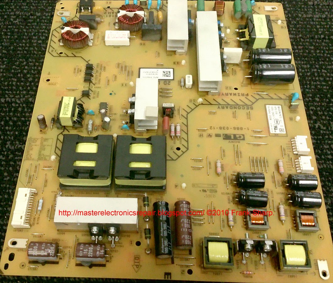
Power Supply (PSU): APS-316 (CH) 1-886-038-12
PWM Power: PWM
MainBoard: 1-885-388-51
IC MainBoard: CXD4727GB, K4B2G1646C-HC
Tuner: Tuner
Control: WIFI: 1-458-355-22, Remote: RM-ED047
Technical Specifications KDL-55HX753
SONY KDL-55HX753
General repair guidelines for TV LCD LED
If the SONY KDL-55HX753 does not turn on, no control lights on the front panel light up or blink, therefore, there is a very high probability of a failure of the APS-316 (CH) 1-886-038-12 power supply module. In some cases, only the processor power regulator may be faulty. In the absence of swollen filter capacitors of the secondary rectifiers, the diagnostics of the power supply should be started by checking the fuse and, if it is broken, it is first necessary to check all the power semiconductor elements of the primary circuit - diodes and transistors for the possibility of an avalanche or thermal breakdown.
If a breakdown of the power switch is detected, it should be remembered that in a switching power supply (IIP) it does not fail by itself for no reason that you should look for by checking other elements of the primary circuit - electrolytic capacitors, PWM PWM controller, which can be checked only by replacement, as well as other semiconductor elements (diodes, transistors, zener diodes).
Sometimes the SONY KDL-55HX753 TV does not have an image, but there is sound, or the image appears and immediately disappears. In this case, there is a possibility of a malfunction of the LED driver - power converter for the backlight LEDs of the LTY550HQ04 panel, or a break in the LED circuit is possible. In such cases, first of all, it is necessary to verify the operability of the electrolytic capacitors of the filter by the power of the backlight unit.
A malfunction in the backlight circuits often occurs due to an open in the power circuit of the LED lines. It is necessary to disassemble the panel and check the LEDs themselves, the soldering of their conclusions, as well as the reliability of the connections in the connectors and the soldering of the conclusions of the connectors.
It is impossible to check the LED line for breaks without disassembling the panel with a multimeter or tester. For these purposes, it is necessary to open all series-connected PN junctions and a voltage of the order of tens of volts will be required, and ideally, a current source. Having disassembled the panel, it is necessary to check each LED separately. Chinese multimeters, as a rule, light up a single 3-volt LED in the forward direction. In the case of using dual 6-volt LEDs, the PN junction of its protective zener diode can serve as a health indicator. In faulty LEDs, the zener diode will either be cut off or broken into short-circuit.
Repair or diagnostics of the 1-885-388-51 motherboard should begin by checking the stabilizers and power converters needed to power the microcircuit and matrix. If necessary, you should update the software (software).
Often, the MB (SSB) card must be replaced in case of complex malfunctions that are difficult to detect. When trying to repair, you should check its elements - CXD4727GB, K4B2G1646C-HC and replace failed chips with new ones. Some malfunctions may be due to the use of BGA soldering technologies in modern Main Board technologies. Typically, such defects are detected by local heating of the chip.
Before replacing the Tuner, if there is no tuning to the channels, you must first check the software and the supply voltage at its terminals. It is also necessary to make sure that the tuner and processor can exchange data via I2C
Once again, we remind TV users: you should not make attempts to repair it yourself without the appropriate knowledge, experience and the necessary qualifications! Trust the repair only to professionals with sufficient experience in the field of electronic equipment repair.
Service Manual 145 pages of 2012 for ---------------------------> KDL-32HX750, KDL-32HX751, KDL-32HX753, KDL-32HX755, KDL-32HX757, KDL-32HX758, KDL-32HX759, KDL-40HX750, KDL-40HX751 -40HX755, KDL-40HX756, KDL-40HX757, KDL-40HX758, KDL-40HX759, KDL-40HX75G, KDL-46HX750, KDL-46HX751, KDL-46HX753, KDL-46HX755, KDL-46HX7575, KDL-46HX7575, KDL-46HX7575, KDL-46HX7575, KDL-46HX7575, KDL-46HX7575, KDL-46HX7575, KDL-46HX75H , KDL-46HX759, KDL-46HX75G, KDL-55HX750, KDL-55HX751, KDL-55HX753, KDL-55HX755, KDL-55HX75G.

 The appearance of MainBoard 1-885-388-51 is shown in the figure below:
1-885-388-51
1-885-388-51 can be used in TVs:
SONY KDL-46HX853 (Panel FQLR460LT01 A-1853-359-B), SONY KDL-40EX653 (Panel LTY400HM10), SONY KDL-40HX853 (Panel FQLR400LT01), SONY KDL-55HX753 (Panel LTY550HQ04), SONY KDL-46HX753 (Panel LTY460HQ05).
The appearance of the power supply
Main features of the device SONY KDL-55HX753:
Installed matrix (LED-panel) LTY550HQ04.
The matrix control uses the Timing Controller (T-CON) 1-895-192-11.
The formation of the necessary supply voltages for all nodes of the SONY KDL-55HX753 TV is carried out by the APS-316 power module, or its analogs using PWM chips.
MainBoard - the main board (motherboard) is a 1-885-388-51 module, using CXD4727GB, K4B2G1646C-HC and others.
The Tuner provides TV reception and channel tuning.
Information from an alternative source:
SONY KDL-55HX753 Chassis AZ3F
Panel Type (Matrix): LTY550HQ04
Motherboard: 1-885-388-51, CXD4727GB, K4B2G1646C-HC
T-con: 1-895-192-11 WQL_C4LV0.1 LJ94-24329D, WIFI: 1-458-355-22,
PSU: APS-316 (CH) 1-886-038-12
Remote control: RM-ED047