 Technical description and composition of the TV SONY KLV-32NX500, type of panel and applicable modules. The composition of the modules.
SONY
Model: KLV-32NX500
Chassis / Version: AZ1-A (5-0)
Panel: T315HW04 V.0
T-CON: T315HW04 V0 31T09-C0E
Inverter (backlight): 4H.V2258.151 V225-6XX
Trans Inverter: 9503AA5CA17 (HF)
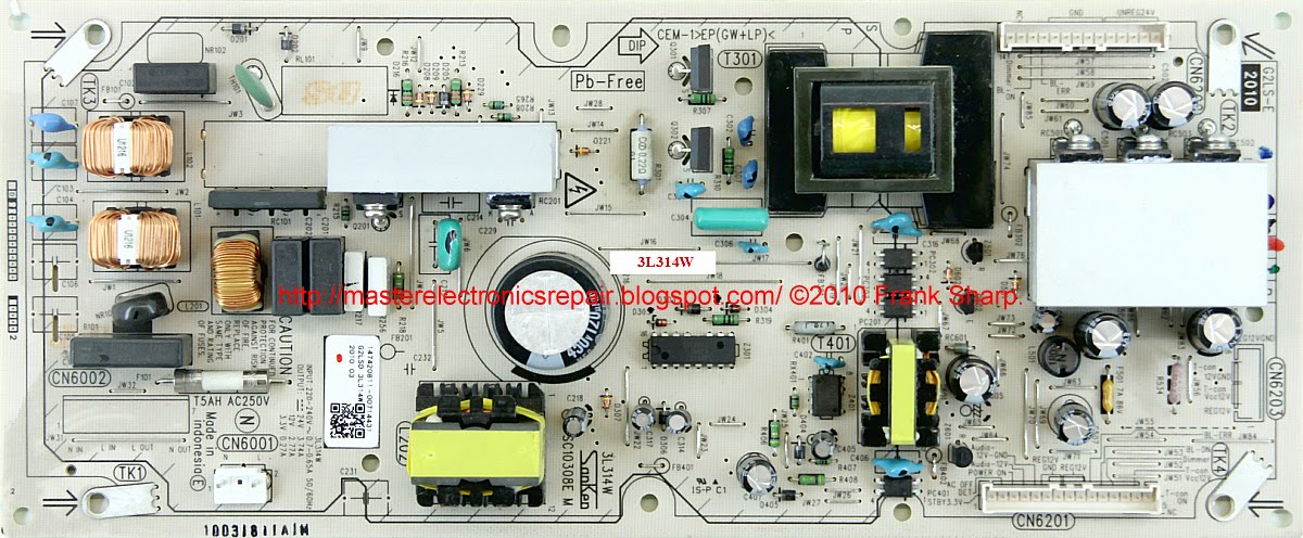
Power Supply (PSU): 3L314W PSC10308F G2LSF
PWM Power: SSC9513 (PWM Resonant), STR-A6079M (Standby)
MainBoard: BAA board, SAA
IC MainBoard: MT5388GF MG, TPA3110D2, H5PS5162FFR, K9F1208UOC
Tuner: TEQE8-L01A
Technical Specifications KLV-32NX500
SONY KLV-32NX500
General recommendations for repairing TV LCD
SONY KLV-32NX500 TV, like any other, it is advisable to start repairing it by inspecting the internal and external visible physical visual changes. It often happens that some damage to elements or connections will help determine the correct direction of troubleshooting and localization of the defect. Elements with visible damage, for example, capacitors swelled up after boiling the electrolyte, charred resistors in certain nodes of the circuit, as well as ring cracks in solders will help the master to guess the causes and possible consequences of the malfunction.
In the case when the KLV-32NX500 does not turn on, does not respond to the remote control and the front panel buttons, does not blink bulbs and does not show any signs of operability, most likely in this case the PSC10308F G2LSF 3L314WA power supply module is faulty. When repairing the power supply, it is advisable to start the diagnostics by checking the mains fuse and, in the event of a break, the cause should be sought in the power semiconductor elements of the pulsed flyback converter of the main PSU. First of all, it is necessary to check the diodes of the bridge of the rectifier of the mains voltage and the power switch of the converter, which can be installed separately on the radiator, or integrated with a PWM controller.
Power switches in flyback converters fail extremely rarely for no reason and, if they are broken, it is necessary to look for a malfunction in the stabilization circuits by checking electrolytic capacitors, semiconductor devices, and resistors in the primary circuit. The cause may be a malfunction of the PWM controller chip, which can only be checked by replacing it with a new or obviously working one.
It is somewhat more difficult to look for a malfunction in the converter of the power module with an active KKM (power factor corrector).
If the SONY KLV-32NX500 TV does not have an image, but there is sound, the malfunction should be sought in the backlight lamp power converter (inverter). It is also necessary to check the serviceability of the electrolytic capacitors of the filter of the secondary rectifiers of the PSU (power supply) for an overstated ESR.
The operation of the power circuits of the inverter and the backlight in the normal mode are controlled by special protection, which is organized for fire safety, for example, to disconnect during short circuits or breaks in high-voltage connections or when the lamps are depressurized. This protection makes it difficult to diagnose and repair the inverter.
When diagnosing with the protection off, special precautions must be taken, because there is a risk of failure of the power elements of the inverter. After the diagnosis, it is imperative to restore the protection circuits for the inverter to operate normally.
The motherboard SAA BAA must be checked if there is no reaction to the remote control and function buttons, the standby indicator blinks or lights up continuously. In such cases, if the power supply circuits of the microcircuits are working, a software update may be necessary.
Before replacing the TEQE8-L01A tuner, if there is no tuning for the channels, first you need to check the supply voltage at its terminals, including the varicap supply (30-33V).
We recommend the owners of the KLV-32NX500 TV for repair only to qualified specialists with experience! Self-repair attempts without the appropriate knowledge and skills can lead to serious negative consequences!
Service / Schematic manual -------------> Sony KLV-26-32NX400, KLV-32-40NX500 Chassis AZ1-A 5-0 KLV-26NX400, KLV-32NX400, KLV-32NX500, KLV-40NX500.

 The appearance of the MainBoard BAA is shown in the figure below:
BAA
BAA can be used in TVs:
SONY KLV-22BX300 (Panel T216XW01 V.3), SONY KLV-22BX301 (Panel 22 "), SONY KLV-26BX301 (Panel V260B3-L05 Rev.C1), SONY KLV-26NX400 (Panel V260B3-L05 Rev.C1), SONY KLV-32BX300 (Panel LTY320AP04), SONY KLV-32BX301 (Panel LTY320AP05 006), SONY KLV-32NX500 (Panel T315HW04 V.0), SONY KLV-40BX400 (Panel LTZ400HM01 A13), SONY KLV-40BX401 (Panel LTY400HM01 A05 ), SONY KLV-32EX300 (Panel LTY320AP04), SONY KLV-40NX500 (Panel T400HW03 v.0).
The appearance of the power supply
Main features of the device SONY KLV-32NX500:
Installed matrix (LCD panel) T315HW04 V.0.
The matrix control uses the Timing Controller (T-CON) T315HW04.
To power the backlight, an inverter 4H.V2258.151 is used. A transformer 9503AA5CA17 (HF) is installed in the inverter converter.
The necessary supply voltages for all nodes of the SONY KLV-32NX500 TV are generated by the 3L314W power module or its analogs using SSC9513 (PWM Resonant), STR-A6079M (Standby) microcircuits.
MainBoard - the main board (motherboard) is a BAA module, using microchips MT5388GF MG, TPA3110D2, H5PS5162FFR, K9F1208UOC and others.
The TEQE8-L01A tuner provides TV reception and channel tuning.
Additional technical information about the panel:
Brand: AUO
Model: T315HW04 V0
Type: a-Si TFT-LCD, Panel
Diagonal size: 31.5 inch
Resolution: 1920x1080, FHD
Display Mode: AMVA, Normally Black, Transmissive
Active Area: 698.4x392.85 mm
Surface: Antiglare (Haze 11%), Hard coating (3H)
Brightness: 450 cd / m²
Contrast Ratio: 5000: 1
Display Colors: 16.7M (8-bit), CIE1931 72%
Response Time: 6.5 (G to G)
Frequency: 60Hz
Lamp Type: 4 pcs CCFL Embedded (Inverter)
Signal Interface: LVDS (2 ch, 8-bit), 51 pins
Voltage: 12.0V