 Technical description and composition of the AKAI LTA-32C904M TV, panel type and applicable modules. The composition of the modules.
AKAI
Model: LTA-32C904M
Panel: V320B1-L06
T-CON: V320B1-C03
Inverter (backlight): I320B1-16A
Power Supply (PSU): JSK4200-014 - 810039684 - 47131.220.0.0116105 Rev1.4
PWM Power: L6599D (PWM Resonant), FAN7530MX (PFC), ICE3B0365 (Standby)
MOSFET Power: 2SK3568, 2SK2837 (PFC)
MainBoard: JUG7.820.265 Ver1.00
IC MainBoard: TDA7266SA, TDA9886SA, PS201, SVP AX68 7668LF
Tuner: AFT7 / W003
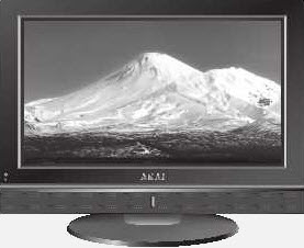
Appearance
AKAI LTA-32C904M
General recommendations for repairing TV LCD
Possible manifestations of defects
- AKAI LTA-32C904M does not turn on, the indicators on the front panel do not light or flash. The TV does not respond to the control buttons and the remote control.
Most often, with such manifestations, the main power module JSK4200-014 is found to be faulty. It is necessary to measure the secondary output voltages, and if they are absent, check the operability of the power switches (2SK3568, 2SK2837 (PFC)) of the converters and rectifier diodes for a short circuit.
In case of breakdowns in the secondary circuits, the converter can operate in a short circuit mode, and during a short circuit in the elements of the primary circuit, the mains fuse usually breaks.
Mos-Fet keys used in switching power supplies usually fail due to a malfunction of other elements that can put it out of operation in key mode or provoke the excess of maximum current or voltage values. It can be supply, damper circuits, or elements of OOS (negative feedback) stabilization. The reason for the breakdown of the power key can be PWM (PWM) L6599D (PWM Resonant), FAN7530MX (PFC), ICE3B0365 (Standby). It is checked only by replacement with a known good one.
- There is no image, but there is sound and reaction to the remote control. Or for a second, the image may appear immediately after switching on.
The defect can be caused by problems in the nodes or elements of the backlight of the display, or in the power supply of the lamps or inverter. If all the electrolytic capacitors of the filter according to the power supply of the inverter are working, make sure that the lamps are working, then you need to check the converter keys and the secondary windings of the transformers.
Sometimes, for diagnostic purposes, it is necessary to disable the inverter protection. In such cases, special care must be taken during work, and the protection circuits should be restored immediately after the repair is completed.
- The TV does not turn on, does not respond to the remote control. The indicator blinks or signals standby mode.
Repair or diagnostics of the JUG7.820.265 motherboard should begin by checking the stabilizers and power converters needed to power the chips and matrix. If necessary, update or replace the software (software). Complex repair of MB (SSB) is possible only in the conditions of a service center with the necessary equipment. Checking or replacing elements TDA7266SA, TDA9886SA, PS201, SVP AX68 7668LF requires the necessary training and professional skills in repairing modules at the component level. Problems associated with the use of BGA soldering technologies can sometimes be diagnosed by warming up.
In the absence of tuning to the channels of on-air or cable television, you should make sure that the software is correct, as well as in accordance with the ratings of the supply voltages at the terminals of the tuner AFT7 / W003. It is also necessary to check the presence of pulses of data exchange between the tuner and the processor via the I2C bus using an oscilloscope.
TV users and owners must remember that attempts to self-repair an AKAI LTA-32C904M TV without the appropriate qualifications and the necessary experience can lead to serious negative consequences!
SCHEMATIC DIAGRAM / SERVICE MANUAL ------------------> LTA-26-32C904
AKAI LTA-32C904 chassis LS01
Panel: V320B1-L04
Tuner: CDT-6GPL22-00
MAIN: JUG7.820.015 VER2.0
Main: T5BS4 - 9999, 39VF040 , 24C64
T-CON: V320B1-C03
INVERTER: 27-D008101, PSU: FSP205-5E01

 The appearance of the MainBoard JUG7.820.265 is shown in the figure below:
JUG7.820.265
JUG7.820.265 can be used on TVs:
AKAI LTA-32C904M (Panel V320B1-L06), AKAI LTA-26C904 (Panel V260B1-L02 ), HYUNDAI H-LCD3200 (Panel LC320WX3 (SL)(C1)), SUPRA STV-LC2611W (Panel T260XW02), SUPRA STV-LC3204WD (Panel LTA320AP02).
PSU Advanced
The JSK4200-014 power module is installed in the LTA-32C904M TV using the PFC (Power Factor Correction) circuitry acting as an active filter to eliminate the higher harmonic components of the current consumption. The boost converter based on the FAN7530MX PWM controller does not allow the input rectifier filter's electrolytic capacitor to be connected to the network directly through open diodes when the charge current determines its reactance (about 15-30 ohms at a frequency of 50 Hz). As a result of the conversion, the charging current of the capacitor will be determined in such a way that the envelope of the high-frequency pulses of the input current will repeat the phase and shape of the sine wave of the input voltage. The health check of the PFC unit is carried out by measuring the DC voltage on the capacitor of the rectifier network. In operating mode, it should be around 380V, in standby approximately 300V.
The appearance of the power supply
Key Features of the AKAI LTA-32C904M:
Installed matrix (LCD panel) V320B1-L06.
The matrix control uses the Timing Controller (T-CON) V320B1-C03.
To power the backlight used inverter I320B1-16A.
The required supply voltages for all nodes of the AKAI LTA-32C904M TV are generated by the JSK4200-014 power supply module or its analogs using L6599D (PWM Resonant), FAN7530MX (PFC), ICE3B0365 (Standby) microcircuits and 2SK3568, 2SK2837 (PFC) power switches .
MainBoard - the main board (motherboard) is a JUG7.820.265 module, using chips TDA7266SA, TDA9886SA, PS201, SVP AX68 7668LF and others.
The AFT7 / W003 tuner allows you to receive television programs and tune to channels.
Additional technical information about the panel:
Brand: CMO
Model: V320B1-L06
Type: a-Si TFT-LCD, Panel
Diagonal size: 32.0 inch
Resolution: 1366x768, WXGA
Display Mode: Super MVA, Normally Black, Transmissive
Active Area: 708.954x398.592 mm
Surface: Antiglare (Haze 25%), Hard coating (3H)
Brightness: 400 cd / m²
Contrast Ratio: 1200: 1
Display Colors: 16.7M (8-bit), CIE1931 75%
Response Time: 6.5 (G to G)
Frequency: 60Hz
Lamp Type: 16 pcs CCFL Embedded (Inverter)
Signal Interface: LVDS (1 ch, 8-bit), 30 pins
Voltage: 5.0V