This color monitor
automatically scans all horizontal frequencies from 30KHz to 70KHz, and all
vertical frequencies from 50Hz to 160Hz. This color monitor supports IBM PC,
PC/XT, PC/AT, personal System/2 (PS/2), Apple Macintosh, and compatible users
crisp text and vivid color graphics display when using the following graphics
adapters : (VGA, 8514/A, Super VGA, VESA and XGA and Apple Macintosh Video
Card). And so, this color monitor has a maximum horizontal resolution of 1280
dots and a maximum vertical resolution of 1024 lines for superior clarity of
display.
By
accepting analog signal inputs which level is zero to 0.7 Volts. This color
monitor can display and unlimited palette of colors depending on the graphics
adapter and software being used.
Degaussing is always
required when adjusting purity or convergence.
• The
white balance adjustment has been done by a color analyzer in factory. The
adjustment procedure,
described
in the service manual is made by a visual check.
• Allow
20 minutes warm-up time for the display before checking or adjusting only
electrical
specification
or function.
• Reform
the lead wire after any repair work.
Caution For Servicing
• In
case of servicing or replacing CRT, high voltage sometimes remains in the anode
of the CRT. Completely discharge high voltage before servicing or replacing CRT
to prevent a shock to the serviceman.
ALIGNMENT PROCEDURE
Standard
Adjustment Conditions
1.
Power source voltage : AC 120V, 60Hz/AC 220V, 50Hz.
2. Aging : Take at least 20 minutes warm-up time.
3. Signals.
Video : Analog 0.7Vpp 75Ωterminal positive polarity
Synchronizing : TTL Level Negative/Positive Separate/Composite
Deflection frequency
Horizontal Frequency : 30KHz - 70KHz
Vertical Frequency : 50Hz - 160Hz
Pre-Adjustment
1.
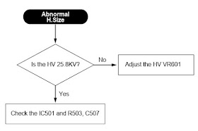
High Voltage Adjustment
Adjust 25.8K Vdc between Anode cap and ground at a cross hatch pattern of 60KHz
by using VR 601.
2. H.Size Adjustment
(a) Receive a cross hatch pattern of 60KHz
(b) Set the H-Size control to the maximum on OSD menu.
Method to launch the factory mode [Service mode]
Push
the menu button.
Push the menu button and plus control button ( + ) for 5 times in same time.
Main Adjustment
1.
Setting the Controls
Set the value of items as following.
Contrast : Max. (OSD value up to 100)
Brightness : Center (Set the OSD value to 50)
2. H.size, V.size, H.phase, V.position, Pincushion, Trapezoid
Receive the cross hatch pattern of Factory preset mode.
H.size, V.size, H.phase, V.position, Pincushion, Trapezoid are adjusted at each
mode.
In Factory, Auto Alignment was done at each mode. Therefore, Factory preset
mode has it’s own value according to each control.
3. Focus
(a) Set brightness control to center and contrast control to MAX.
(b) Receive all “H” character pattern of 60KHz mode signal.
(c) Adjust the Focus control of FBT to obtain best Focus (static focus and
Dynamic focus).
4. Geometric Distortion Adjustment
(a) Receive the cross hatch pattern of VGA mode signal by using the signal
generator.
(b) Pin balance, Parallelogram are adjusted the best geometric status.
(c) Repeat the adjustment at each mode.
5. White Balance Adjustment
(a) Receive a full white pattern of 60KHz mode.
(b) Set the bright control and contrast control to the maximum and receive the
all black pattern.
(c) Adjust the G1 control in Factory mode to 0.8 Ft/L.
(d) Select the R, G, B Bias on the OSD menu and adjust the +/– key to get the
color coordinates in X=0.281, Y=0.311.
(e) If the screen luminosity is changed, repeat (c) & (d) to get the 0.8
Ft/L screen luminosity.
(f) Set the brightness control to the center and contrast control to the
maximum.
(g) Receive a full white pattern.
(h) Select the R, G, B gain
on the OSD menu and adjust the +/– key to get the color coordinates in X=0.281±0.02,
Y=0.311±0.02.
(i)
Adjust the sub contrast (ABL) control to get the screen luminosity to 30.0
Ft/L.
6.
Static Convergence Adjustment
(a)
Apply a magenta cross hatch pattern on display.
(b)
Adjust the focus from the best over all focus on the display.
Also
adjust the brightness to the desired condition.
(c)
Vertical red and blue lines are converged by varying the angles between the two
tabs of the 4-pole magnets.
(d)
Horizontal red and blue lines are converged by varying the tabs together
keeping the angle between them constant.
(e)
Apply a yellow cross hatch pattern on the display.
(f)
Vertical green and red lines are converged by varying the angle between the two
tabs of the 6-pole magnets.
(g) Horizontal
green and red lines are converged by varying the tabs together and keeping the
angle between them constant.
Troubleshooting chart


