 LG Mini Hi-Fi system OM5540 330W – how to update the firmware, repair hints, schematic

How
to update the firmware of LG OM5540 Mini hi-fi system, SMPS and main amplifier
schematic, troubleshooting, ICs and connector voltages
Hidden key mode
Disc Lock On/Off (CD Function Only Active)
Front Key : STOP
Front Key : STOP
RCU Key : STOP
Check Version and Option codeFront Key : STOP
Check Version and Option codeFront Key : STOP
RCU Key : PLAY/PAUSEYou can change [Audio MCU Version <-> CD Controller Version <->
EEPROM Option] by SKIP+/-.
Clear EEPROMFront Key : STOP
Clear EEPROMFront Key : STOP
RCU Key : SKIP-Edit EEPROM
Front Key : STOP
RCU Key : SKIP+ You can change the digit of option by SKIP+/-.You can edit 0~f by REPEAT or PLAY/PAUSE key.
Bluetooth DUT
Bluetooth DUT
Front Key : STOP
RCU Key : PROGRAMBluetooth model only
Power Disc Lock On/Off (CD Function Only Active)
Power Disc Lock On/Off (CD Function Only Active)
Front Key : STOP
RCU Key : EQ
Amp Clip On/Off
Amp Clip On/Off
Front Key : STOP
RCU Key : Mute
Amp Clip Mode Change (Amp Clip On > Amp Clip Off > Level Down display).
Amp Clip Mode Change (Amp Clip On > Amp Clip Off > Level Down display).
Service information for
EEPROM

PROGRAM DOWNLOAD & UPDATE
MICOM PROGRAM
Download program file name must be MICOM_OM5540_YYMMDDX.HEX
If security program (Water Wall) is activated on your PC, you must save the file to the USB storage device and disable the security software, then download the file to your set. Downloading file proceeds in the same way at USB1 function and USB2 function.
Caution: When downloading the file, you should neither unplug the USB device, change to the other function, nor power off the device. USB device must be unplugged when the downloading process is completed.

MCS PROGRAM
Download program file name must be HG440_OM5540_YYMMDDX.bin
If security program (Water Wall) is activated on your PC, you must save the file to the USB storage device and disable the security software, then download the file to your set. Downloading file proceeds in the same way at USB1 function and USB2 function.
Caution: When downloading the file, you should neither unplug the USB device, change to the other function, nor power off the device. USB device must be unplugged when the downloading process is completed.

EQ PROGRAM
Download program file name must be EQ_PRG.BIN
If security program (Water Wall) is activated on your PC, you must save the file to the USB storage device and disable the security software, then download the file to your set. Downloading file proceeds in the same way at USB1 function and USB2 function.
Caution: When downloading the file, you should neither unplug the USB device, change to the other function, nor power off the device. USB device must be unplugged when the downloading process is completed.

Troubleshooting
NO POWER
If the unit doesn’t work by no power problem, repair the set according to the following
(1) FUSE & BRIDGE DIODE
Please check and replace F901, BD901, TH901 or TH903 on SMPS board.
1) Check if the fuse F901 is open or short-circuit.
2) Check if the bridge diode BD901 is short-circuit by over current with a digital multi meter.
3) Check if the NTC thermistor TH901 or TH903 is normal or open.
(2) D951
Please check and replace D951 on SMPS board.
1) Check the anode-cathod voltage of D951 with a digital multi-meter, it is normally 0.2 ~ 0.3 V.
If it doesn’t have any voltage, it’s destroyed. Replace it with a new one.
Please check and replace D951 on SMPS board.
1) Check the anode-cathod voltage of D951 with a digital multi-meter, it is normally 0.2 ~ 0.3 V.
If it doesn’t have any voltage, it’s destroyed. Replace it with a new one.

NO BOOTING WHEN POWER ON THE SET
The set doesn’t work when press the power button on the front board or the remote control.
(1) FLASH MEMORY
Please check and replace IC503 on MAIN board.
1) Check 5.6 V to CN501 in standby mode.
If there is no 5.6 V, check the SMPS.
2) Check 12 V, F+, F- and PVDD when power on the set.
- If the set doesn’t work regardless of what the KEY1 changes high to low while pressing the power button.
X500 and X501 work normally but, if you can not power on the set, replace IC501 with a new one on the MAIN board.

VFD IS NOT DISPLAYED WHEN POWER ON THE SET
When power on the set, any icons or characters on VFD are not displayed.
When power on the set, any icons or characters on VFD are not displayed.
Please
check and replace DIG400 on FRONT board.
1) Check if VKK, FL+ and FL- are output from SMPS to VFD via the MAIN board.
2) Check if IC501 outputs VFD_D0, VFD_CLK and VFD_STB to the FRONT board.
3) Check the GR signal(pulse signal) of IC301 on the FRONT board.
Check the SG signal(pulse signal) of IC301 on the FRONT board.
If the GR and SG signal isn’t output, replace IC301 with a new one.
If the GR and SG signal is output, replace DIG302 with a new one.

NO SOUND
There is no sound output by DIGITAL AUDIO AMP DAMAGE
There is no sound output by DIGITAL AUDIO AMP DAMAGE
(1)
BY DIGITAL AUDIO AMP DAMAGE (IN ALL FUNCTIONS)
Please check and replace IC700 on MAIN board.
1) Check PWM_FL± signals from IC601 to IC700 each input function.
If no signal, check if I2S audio signals are entered to IC601.
2) Check the following I2S signal flow. < I2S audio signal Interface >
- MCS_BCK: IC501_Pin E1 --> IC601_Pin23
- MCS_LRCK : IC501_Pin D1 --> IC601_Pin22 (44.1 kHz)
- MCS_DATA_OUT : IC501_Pin E2 --> IC601_Pin24
- MCS_MCLK : IC501_Pin D2 --> IC201_Pin44
If there is any trouble, check the power for each IC. The power is normal but, if the signal waveform to the IC is distorted or no signal, replace it with a new one.
3) Check PVDD.
If PVDD is abnormal, check the SMPS.
4) Check +12 V for driving the gate of AMP IC.
a. All the powers are normal, but if +12 V is low, there is possible for AMP IC to be damaged.
b. Remove L702, L706 one by one.
When removed a inductance, if +12 V is recovered, the IC connected to it was damaged.
c. Replace the IC with a new one.
5) Check the impedance between IC700_OUT_A/OUT_D & GND.
a. If the impedance is 0 Ω, the IC must be damaged.
b. After removing the heat sink, replace it with a new one.
There is no sound output in the USB FUNCTION
(2) IN THE USB FUNCTION
Please check and replace IC501 on MAIN board & IC460 on USB board.
1) Check +5 V_USB to USB board.
If the USB LED are turned on, the voltage is okay, if so not, check +5.6 V to pin3 of CN460.
2) Check USB D1± or USB D2± from MAIN board to USB board.
a. Check 2.0_D1± signals(pin U7, U8) or 1.1_D1± signals(pin A7, A8) to IC501on MAIN board.
b. Check USB± signals to CN421 (pin 2, 3, 5, 6).
If there is any trouble, check the power for each IC. The power is normal but , if the signal waveform to the IC is distorted or no signal, replace it with a new one.
3) Check if “Digital audio AMP block” on item 4-(1) is normal.
There is no sound output in the AUX FUNCTION
(3) IN THE AUX FUNCTION
Please check and replace IC201 on MAIN board.
1) Check AUX_L/R signals to IC201 (Pin23, 24).
2) Check if MCS_BCK, MCS_LRCK & MCS_MCLK are entered from IC501 to IC201.
3) Check if ADC_DATA is entered from IC201 to IC501.
Ö If no signal, check +5 V & +3.3 V(ADC) for IC201. If is NG, replace it a new one.
4) Check the following I2S signal flow from IC501 to IC601. (Refer to item 4-(1).)
If there is any trouble, check the power for each IC. The power is normal but, if the signal waveform to
the IC is distorted or no signal, replace it with a new one.
5) Check if the digital audio AMP block is okay. Refer to “Digital Audio AMP” guide on Item 4-(1).
If AMP is damaged, replace it with a new one.
There is no sound output in the TUNER FUNCTION
(4) IN THE TUNER FUNCTION
Please check and replace IC201, TU500 on MAIN board.
1) Check if TUNER_LR is entered from Pin1, 3 of TU500 to IC201(Pin26, 27).
If no signals, check +3.3 V for tuner power.
Check if the tuner control signals (CLK, DAT, CE, RST, SLT) are entered from IC501 to TU500.
If it doesn’t work, replace TUNER with a new one.
2) Check if MCS_BCK, MCS_LRCK, & MCS_MCLK are entered from IC501 to IC201.
3) Check if ADC_DATA is entered from IC201 to IC501.
If no signal, check +5 V & +3.3 V(ADC) for IC201. If is NG, replace it with a new one.
4) Check the following I2S audio signal flow from IC501 to IC601. (Refer to item 4-(1).)
If there is any trouble, check the power for each IC. The power is normal but, if the signal waveform to the IC is distorted or no signal, replace it with a new one.
5) Check if the digital audio AMP block is okay. Refer to “Digital Audio AMP” guide on item 4-(1).
If AMP is damaged, replace it with a new one.
There is no sound output in the PORTABLE FUNCTION
(5) IN THE PORTABLE FUNCTION
Please check and replace IC201 on MAIN board.
1) Check PT_L/R signals to IC201 (Pin9, 10).
2) Check if MCS_BCK, MCS_LRCK, & MCS_MCLK are entered from IC501 to IC201.
3) Check if ADC_DATA is entered from IC201 to IC501.
If no signal, check +5 V & +3.3 V(ADC) for IC201. If NG, replace it a new one.
4) Check the following I2S signal flow from IC501 to IC601. (Refer to item 4-(1).)
If there is any trouble, check the power for each IC. The power is normal but, if the signal waveform to the IC is distorted or no signal, replace it with a new one.
5) Check if the digital audio AMP block is okay. Refer to “Digital Audio AMP” guide on Item 4-(1).
If AMP is damaged, replace it with a new one.

There is no sound output in the MIC FUNCTION
Please
check and replace IC203 on MAIN board and IC420 on front MIC board.
[ How to troubleshoot (Countermeasure) ]
1) Check MIC_SIG signal, from JACK421, JACK422 to IC420 (Pin3) on front MIC board.
2) Check MIC_SIG signal from IC420 (Pin4) to CN423.
If no signal, check +5 V for IC420. If NG, replace it a new one.
3) Check MIC_SIG signal from CN423 (Pin4) to CN420.
4) Check if MCS_BCK, MCS_LRCK, & MCS_MCLK are entered from IC501 to IC203.
5) Check if ADC_DATA is entered from IC203 to IC501.
If no signal, check +5 V & +3.3 V(ADC) for IC203. If NG, replace it a new one.
6) Check the following I2S signal flow from IC501 to IC601.(Refer to item 4-(1).)
If there is any trouble, check the power for each IC. The power is normal but, if the signal waveform to the IC is distorted or no signal, replace it with a new one.
7) Check if the digital audio AMP block is okay. Refer to “Digital Audio AMP” guide on item 4-(1).
If AMP is damaged, replace it with a new one.

SMPS schematic

Main amp schematic

Main DSP schematic
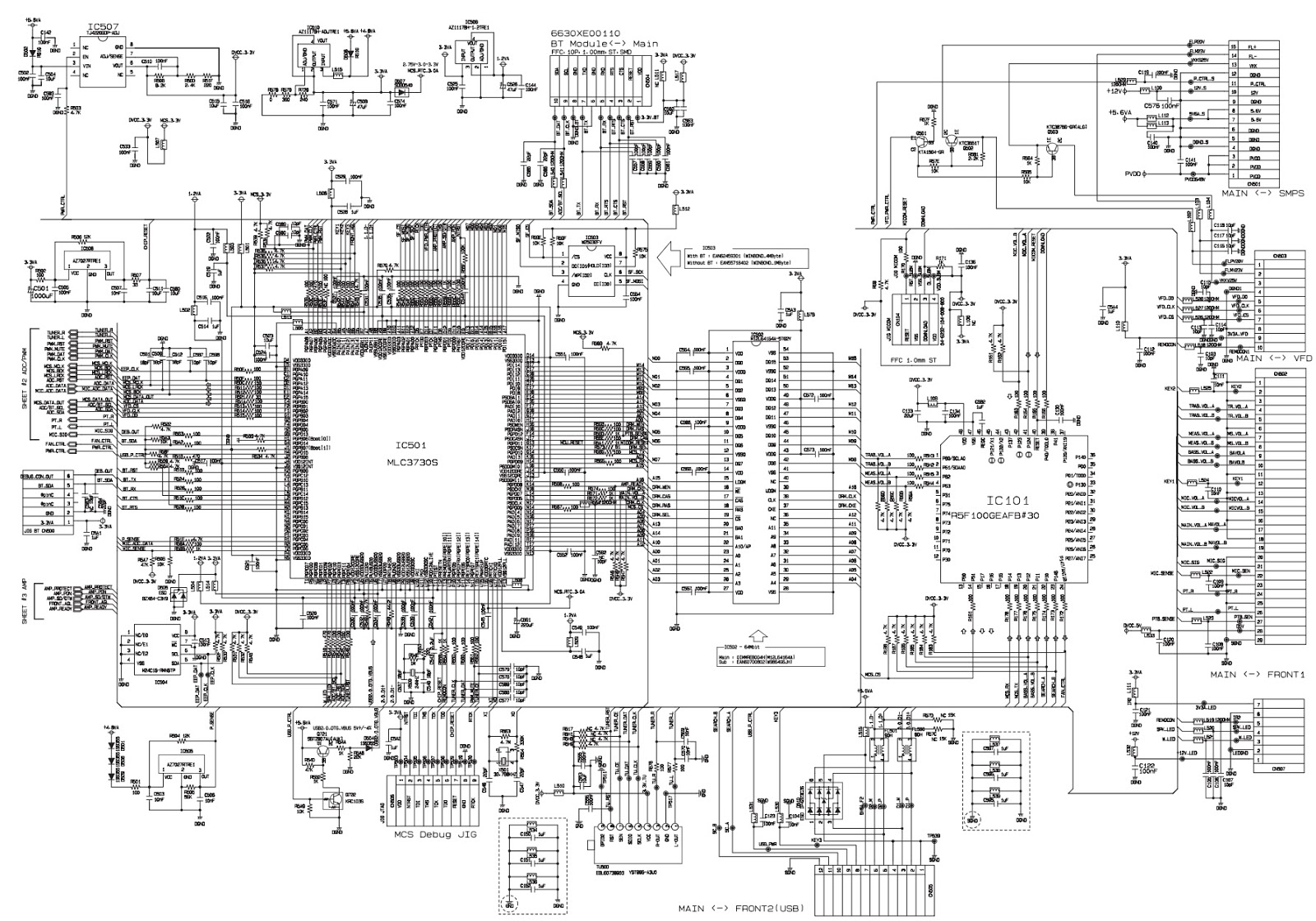
IC voltages and connectors
