TS590S Kenwood HF 50MHz ALL MODE TRANSCEIVER How to disassemble, circuit description and schematic
Disassemble
procedure - Removing
the torque changeover lever
Insert the tip of a flat-head
screwdriver (or other implement) under the tab of the torque changeover lever,
and then lift the tab using the tip of the flat-head screwdriver. (1)
Caution: Be careful not to damage
the panel when lifting.
Turn the lever section of the
torque changeover lever to the right, as in the position described in step 1.
(2)
Lift the torque changeover lever
and remove it from the panel. (3)
Mounting
the torque changeover lever
Insert the torque changeover
lever by aligning the three tabs of the panel. (1)
Slightly turn the lever section
of the torque changeover lever to the left (3) while pressing the surface near
the tab at the lower right of the torque changeover lever (2).
Caution: Confirm that the torque
changeover lever is caught by the lower right tab of the panel.
Turn the lever section of the
torque changeover lever to the left (4) while pressing the surface near the tab
at the upper right of the torque changeover lever (5), and then mount it onto
the panel.

Procedures
when Replacing the Diode (1SR139-400) for hand mounting
When replacing the diode (D304:
1SR139-400) used by the Control unit (A/3) (PCB number: J79-0279-09), cut the
leg of a new diode.
Bend the leg of the diode as
shown in the figure.
Solder the diode between Q61
(Collector) and the solder pad (Base) of the Control unit (A/3), as shown in
the figure.
Confirm the direction of the
cathode band when installing the diode.
Install the diode so that it is
positioned on the dotted line.
Install the diode so that its height from the
surface of the PCB is 4mm (0.16 inches) or less (Height of rubber sheet (G11-4536-04):
4mm (0.16 inches)).
Precautions for Reassembly
Perform the following steps when
assembling the bottom side of the transceiver.
1. Separate the two coaxial
cables (E37-1495-05, E37-1496-05) as shown in the figure.
2. Push the two flat cables (E37-1491-05,
E37-1492-05) into the gap of the chassis so they do not come into contact with
the cabinet.

Caution
for Replacing the LED (B30-2322-05, B30-2323-05)
When replacing the “B30-2322-05”
or “B30-2323-05” LED used by the Display unit (A/6), order and replace the LED
for service into which the rank is divided according to brightness, according
to the following procedures, so that the brightness of the LED backlight
remains uniform after replacing the LED.
Confirm whether the “A” or “Z”
stamp is pushed on the foil side of Display unit (A/6).
Order and replace the LED for
service as shown in the following table according to whether stamp “A” or “Z”
exists or not.

Frequency
Configuration
Figure shows the frequency
configuration of this transceiver.
While transmitting, FM mode
operates in a double conversion and other modes (AM, SSB, CW, FSK) operate in a
triple conversion.
While receiving, the first IF
operates in 73.095MHz triple conversion. In modes other than FM, the third IF
is 24kHz, and the IF signal is converted by an A/D converter and input into
DSP. The FM mode is detected in the FM IC, and the audio signal is converted by
an A/D converter and input into the DSP. Under the following conditions, the
first IF operates its reception in 11.374MHz double conversion.
1) Modes other than AM or FM
2) Amateur band within the
1.8/3.5/7/14/21MHz bands
3) DSP filter’s bandwidth is
2.7kHz or lower.

Reference
Signal Generator
The reference frequency (fstd),
which is used to control the individual LO frequencies, oscillates at 15.6MHz
in a crystal oscillation circuit (X502, Q501). This 15.6MHz signal passes
through a buffer (Q502) and is doubled in a multiplier (Q503) to generate a
31.2MHz signal. The 31.2MHz signal is used as a reference signal for LO3 (the
third local oscillator) DDS (IC601). The 31.2MHz signal is doubled in
multipliers (Q504, Q505) to generate a 62.4MHz signal. The 62.4MHz signal is
used as a reference signal for LO1 (the first local oscillator) PLL (IC801). The SO-3 (TCXO unit: 15.6MHz) is configured
as an option in this transceiver, so that you can replace the crystal
oscillation circuit (X502, Q501) with the SO-3. When using the SO-3, remove the
CN903 and CN904 short jumper wires in order to stop the operation of the crystal
oscillation circuit (X502, Q501).
LO1/
LO2/ LO3
LO1
(the first local oscillator)
The VCO (Q806) oscillates at
196.8MHz. Only the double frequency component, 393.6MHz, of this VCO’s
oscillation output is extracted and input into PLL (IC801) pin 6.
This input signal is divided into
1/N within the PLL. Also, the 62.4MHz signal (15.6MHz reference frequency x 4)
is input into PLL pin 8 and divided into 1/R within the PLL. By a phase
comparator in the PLL, the frequency divided into 1/N and the frequency divided
into 1/R are compared, and then the frequency is locked. The comparison
frequency (fø) at this time is 120kHz when transmitting FM, and 2.4MHz otherwise.
393.6MHz signal locked by PLL
(IC801) would be used as reference by DDS (IC803). The output signal from DDS (IC803)
is 12.495MHz to 32.195MHz when RX-1 path is selected, amplified at the broad
band amplifier (IC804), and then goes through BPF and is output as LO1. When
RX-2 path is selected or when
transmitting, 36.5625MHz to 66.5475MHz is output, amplified by the broad band
amplifier (IC804), and then doubled in the multiplier (D652), goes through BPF,
and is output as 73.120MHz to 133.095MHz LO1
LO2 (the second local oscillator)
The reference oscillating
circuit’s output signal 15.6MHz signal passes through a buffer (Q502) and is
doubled in a multiplier (Q503) to generate a 31.2MHz signal. The 31.2MHz signal
is also used as the DDS (IC601)’s reference frequency, and therefore its
resistance is divided. Then, the 31.2MHz signal is doubled in multipliers
(Q504, Q505) to generate a 62.4MHz signal.
The 62.4MHz signal’s high harmonic is cut in the BPF and the signal is
amplified in the amplifier (Q506) to generate LO2. If IFB is selected, the
diode switch (D501) cuts the LO2 output.
LO3
(the third local oscillator)
The LO3 used in the modulator and
the detector is generated in the DDS (IC601). The DDS output signal passes
through the buffer (Q602) and LPF to generate LO3.


Receiver
Circuit
In an amateur frequency band or
mode that requires antiproximate interference, the receive signal passes
through the double conversion RX-1 path, and in other frequency bands and
modes, it passes through the triple conversion RX-2 path.
From the antenna terminal to the
preamplifier (Q236)
The receive signal from the
antenna terminals (ANT1/ANT2) passes through the antenna changeover relay (K44)
in the Final unit (X45-391 A/2), the antenna tuner’s IN/THROUGH changeover
relay (K45), the transmission/reception changeover relay (K46), and an image
filter, and is sent from CN51 to the TX-RX unit (X57-785 A/2)’s CN100 (RAT)
through a co-axial cable.
The signal input into the TX-RX
unit passes through the RX ANT changeover relay (K101) and enters the
attenuator circuit (ATT) which is approximately 12dB. This can be switched to
approximately 20dB by removing the CN101 short jumper. Then, the signal passes
through LPF for IF trap, the surge absorption limiter, and the BC band
attenuating circuit (removes 30kHz to 1.705MHz), and enters the BPF. In the BC
band attenuating circuit, in order to avoid interference by high-output
broadcasting stations, 11.7MHz and 15.5MHz trap circuit is inserted into E type
only.

The BPF divides in the range as
shown in table 3. The BC band’s BPF includes ATT for avoiding cross-modulation
by medium wave band high-output station (ATT ON: CN102=open, CN103=short, ATT
OFF: CN102=short, CN103=open). The transmit signal also passes through the BPF
when transmitting. The preamplifier (Q236) receives the signal passed through
the BPF. In this model, it is an emitter grounding circuit which uses a bipolar
transistor. Q239 switches the emitter’s returning amount to adjust the gain.
Approximately 20dB is gained in 21.5 to 60MHz and approximately 12dB in other
frequencies. The preamplifier circuit can be passed by turning off the PRE
display with the preamplifier key .

From
the preamplifier (Q236) to the second IF frequency (10.695MHz/11.374MHz)
The signal from the preamplifier
(Q236) output to the second IF amplifier 1 (Q451) is spread into 2 paths: RX-1
and RX-2, depending on the frequency band (refer to table) The RX-1 path is selected when the “L” signal
is added to Q273, and the RX-2 path is selected if the “H” signal is added.
The RX-1 path signal passes
through the LPF for IF trap, is integrated with LO1 (12.495 to 32.195MHz) in
the quadbalance first mixer (Q263 to Q266), and is then converted to the first
IF (11.374MHz). The first IF signal passes through the 2-pole MCF (XF301) and
enters the second IF amplifier 1 (Q451). The RX-2 path signal passes through
the LPF for IF trap, is integrated with LO1 (73.120 to 133.095MHz) in the
quadbalance first mixer (Q321 to Q324), and is then converted to the first IF
(73.095MHz). The first IF signal passes through the 2-pole MCF (XF371), and by
the trans-feedback type NFB (negative feedback) first IF amplifier (Q391), is
amplified by approximately 12dB. The amplified signal is mixed with LO2 (62.4MHz)
in the second mixer (D422, D423), converted to the second IF (10.695MHz), and
then enters the second IF amplifier 1 (Q451). The second mixer is a passive
type that uses a diode, and is a bilateral circuit that converts both receive
signal's frequency at the time of reception and transmission signal's frequency
at the time of transmission. The second
IF signal that passed through the RX-1 or RX-2 path is amplified by
approximately 13dB in the second IF amplifier 1 (Q451), and is then divided
into 2 paths: the NB (noise blanker) circuit and the blanking circuit (D461 to
D464). Blanking is carried out by D461 to D464.
Then, the second IF signal passes through the IF filter.
One
of 5 filters is selected, depending on the frequency and the mode (refer to
table).
The second IF signal that passed
through the IF filter enters the AGC circuit (diode ATT circuit: D522 to
D524). The AGC voltage output from the
DSP is added to D522 to D524, the change of AGC voltage changes the current on
the pin diode and controls the attenuation of the signal passing through. And,
the second IF amplifier 2 (Q541) and the second IF amplifier 3 (Q521, Q522)
altogether amplify by the total of approximately 32dB, and the signal passes
through the simplified diode ATT circuit (D525). The voltage determined in the
adjustment mode is added to D525, and adjusts the difference of the total gains
of the RX-1 and RX-2 paths.

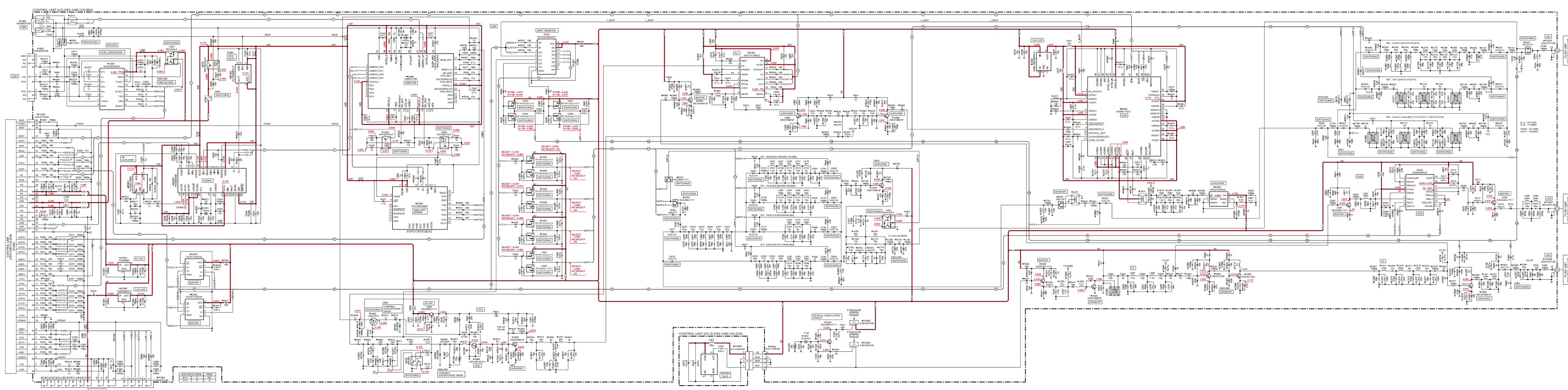
Kenwood
TS590s Schematic