REPAIRING AND NOT THROWING AWAY

Richtige Fernseher haben Röhren!

Richtige Fernseher haben Röhren!

In Brief: On this site you will find pictures and technical information about Service Modes, Circuit Diagrams, Firmware Update procedure, Disassemble procedure, Universal remote control set-up codes, Troubleshooting and more....

If you go into the profession, you will obtain or have access to a variety of tech tips databases HERE IT IS Master Electronics Repair !.

These are an excellent investment where the saying: 'time-is-money' rules. However, to learn, you need to develop a general troubleshooting approach - a logical, methodical, method of narrowing down the problem. A tech tip database might suggest: 'Replace C536' for a particular symptom. This is good advice for a specific problem on one model. However, what you really want to understand is why C536 was the cause and how to pinpoint the culprit in general even if you don't have a service manual or schematic and your tech tip database doesn't have an entry for your sick TV or VCR.

While schematics are nice, you won't always have them or be able to justify the purchase for a one-of repair. Therefore, in many cases, some reverse engineering will be necessary. The time will be well spent since even if you don't see another instance of the same model in your entire lifetime, you will have learned something in the process that can be applied to other equipment problems.
As always, when you get stuck, checking out a tech-tips database may quickly identify your problem and solution.In that case, you can greatly simplify your troubleshooting or at least confirm a diagnosis before ordering parts.

Happy repairing!
Today, the West is headed for the abyss. For the ultimate fate of our disposable society is for that society itself to be disposed of. And this will happen sooner, rather than later.

How to use the site:

- If you landed here via any Search Engine, you will get what you searched for and you can search more using the search this blog feature provided by Google. You can visit more posts scrolling the left blog archive of all posts of the month/year,
or you can click on the main photo-page to start from the main page. Doing so it starts from the most recent post to the older post simple clicking on the Older Post button on the bottom of each page after reading , post after post.

You can even visit all posts, time to time, when reaching the bottom end of each page and click on the Older Post button.

- If you arrived here at the main page via bookmark you can visit all the site scrolling the left blog archive of all posts of the month/year pointing were you want , or more simple You can even visit all blog posts, from newer to older, clicking at the end of each bottom page on the Older Post button.
So you can see all the blog/site content surfing all pages in it.

- The search this blog feature provided by Google is a real search engine. If you're pointing particular things it will search IT for you; or you can place a brand name in the search query at your choice and visit all results page by page. It's useful since the content of the site is very large.

Note that if you don't find what you searched for, try it after a period of time; the site is a never ending job !

..............The bitterness of poor quality is remembered long after the sweetness of todays funny gadgets low price has faded from memory........ . . . . . .....
Don't forget the past, the end of the world is upon us! Pretty soon it will all turn to dust!

©2010, 2011, 2012, 2013, 2014 Frank Sharp - You do not have permission to copy photos and words from this blog, and any content may be never used it for auctions or commercial purposes, however feel free to post anything you see here with a courtesy link back, btw a link to the original post here , is mandatory.
All posts are presented here for informative, historical and educative purposes as applicable within fair use. NOTHING HERE IS FOR SALE !

Showing posts with label EPSON. Show all posts

Wednesday, 10 April 2019

EPSON POWERLITE PRO G6050W - G6150 - G6450WU - G6550WU - G6750WU - G6800 - G6900WU – HOW TO CLEAN THE AIR FILTER – HOW TO REPLACE THE PROJECTOR LAMP – HOW TO RESET THE LAMP HOUR

Epson PowerLite Pro G6050W - G6150 - G6450WU - G6550WU - G6750WU - G6800 - G6900WU – How to clean the air filter – How to replace the projector lamp – How to reset the lamp hour


Epson PowerLite Pro G6050W - G6150 - G6450WU - G6550WU - G6750WU - G6800 - G6900WU
Cleaning the Air Filter
You need to clean the projector's air filter in the following situations:
# The filter or vents get dusty.
# You see a message telling you to clean it.
# The projector's filter light flashes green.
1. Turn off the projector and unplug the power cord.
2. Slide the air filter cover latch and open the air filter cover.
3. Pull the air filter out of the projector
4. Tap each side of the air filter 4 to 5 times to shake off any excess dust.
Caution: Do not use excessive force when tapping the air filter, or it may crack and become unusable. Do not rinse the air filter in water, or use any detergent or solvent to clean it. Do not use canned air; the gases may leave a residue, or push dust and debris into the projector's optics or other sensitive areas.
5. Vacuum the front of the air filter (the side with the tabs) to remove any remaining dust.
Note: If dust is difficult to remove or the air filter is damaged, replace the air filter.
6. Place the air filter back in the projector as shown and push gently until it clicks into place.
7. Close the air filter cover.
Replacing the Lamp
Before you replace the lamp, let the projector cool down for at least one hour so the lamp will not be hot.
Warning: Let the lamp fully cool before replacing it to avoid injury.
You can replace the lamp while the projector is mounted to the ceiling, if necessary.
1. Turn off the projector and unplug the power cord.
2. Allow the projector lamp to cool down for at least one hour.
3. Use the screwdriver included with the replacement lamp to loosen the screws securing the lamp cover, and then remove the lamp cover.
Warning: If the lamp is broken, glass fragments may be loose inside the lamp chamber. Be careful removing any broken glass to avoid injury.
4. Loosen the screws securing the lamp to the projector. The screws do not come all the way out.
5. Hold the lamp by its handle and gently pull it out of the projector.
6. Gently insert the new lamp into the projector. If it does not fit easily, make sure it is facing the right way.
Caution: Do not touch any glass on the lamp assembly to avoid premature lamp failure.
7. Push in the lamp firmly and tighten the screws to secure it.
8. Replace the lamp cover and tighten the screws to secure it.
Resetting the Lamp Timer
You must reset the lamp timer after replacing the projector's lamp to clear the lamp replacement message and to keep track of lamp usage correctly.
Note: Do not reset the lamp timer if you have not replaced the lamp to avoid inaccurate lamp usage information.
1. Turn on the projector.
2. Press the Menu button.
3. Select the Reset menu and press Enter.
4. Select Reset Lamp Hours and press Enter.
You see a prompt asking if you want to reset the lamp hours.
5. Select Yes and press Enter.
6. Press Menu or Esc to exit the menus.

Monday, 8 April 2019

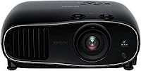
EPSON 3D HD PROJECTOR – EPSON EH-TW6600 – HOW TO REPLACE THE PROJECTOR LAMP – HOW TO CLEAN THE AIR FILTER – HOW TO RESET THE LAMP HOUR TIMER


Epson 3D HD Projector – Epson EH-TW6600 – How to replace the projector lamp – How to clean the air filter – How to reset the lamp hour timer


Cleaning the air filter
Do not use sprays that contain flammable gas to remove dirt and dust from the projector's lens, air filter, and so on. The projector may catch fire due to the high internal temperature of the lamp
Clean the air filter if dust has accumulated on the air filter or when the following message is displayed.
"The projector is overheating. Make sure nothing is blocking the air vent, and clean or replace the air filter.
Attention
# If dust collects on the air filter, it can cause the internal temperature of the projector to rise, and this can lead to problems with operation and shorten the optical engine's service life. It is recommended that you clean the air filter at least once every three months. Clean them more often than this if using the projector in a particularly dusty environment.
# Do not rinse the air filter in water. Do not use detergents or solvents.
# Lightly brush the air filter to clean it. If it is brushed too strongly, dust will be ground into the air filter and cannot be removed.
How to clean the air filter 
1.Press the POWER control or the control panel to turn off button on the remote the power, and then disconnect the power cord.
2.Remove the air filter cover.
Hook your finger into the tab on the air filter cover, and remove it downward.
3.Remove the air filter.
Grip the knob in the center of the air filter and pull it out.
4.Hold the air filter facing down and tap with the surface it 4 or 5 times to remove the dust.
Turn it over and tap the other side in the same way.
If the air filter is hit too hard, it may become unusable due to deformities and cracks.
5. Remove any dust remaining on the air filter by using a vacuum cleaner from the front side.
6. Install the air filter.
Grip the air filter by the knob in the center and insert it straight.
7. Install the air filter cover. Fasten the upper catch and then the lower one.
Clean the projector's surface by wiping it gently with a soft cloth.
If it is particularly dirty, moisten the cloth with water containing a small amount of neutral detergent, and
then firmly wring the cloth dry before using it to wipe the surface.
Lamp replacement period
The lamp replacement message is se and quality of the projected images. The message display time t to appear after 3400H in order to changes depending on the usage maintain the initial brightness situation, such as the color mode setting and so on.
If you continue to use the lamp after the replacement period has passed, the possibility that the lamp may explode increases. When the lamp replacement message appears, replace the lamp with a new one as soon as possible, even if it is still working.
Depending on the characteristics of the lamp and the way it has been used, the lamp may become darker or stop working before the lamp warning message appears. You should always have a spare lamp unit ready in case it is needed.
Replacing the lamp
When replacing the lamp because it has stopped illuminating, there is a possibility that the lamp may be broken. If replacing the lamp of a projector that has been suspended from the ceiling, you should always assume that the lamp is cracked, and remove the lamp cover with care. When you open the lamp cover, small shards of glass could fall out. If any shards of glass get into your eyes or mouth, contact a doctor immediately.
Do not touch the lamp cover immediately after turning off the projector as it is still hot. Wait until the lamp has cooled down sufficiently before removing the lamp cover. Otherwise, you could get burnt.
1. Press the POWER control or the control panel to turn off button on the remote the power, and then disconnect the power cord.
2. Loosen the lamp cover fixing screw
3. Remove the lamp cover. Slide the lamp cover straight forward and remove it.
4. Loosen the two lamp fixing screws.
5. Remove the old lamp.
Grip the knob firmly and pull it straight out.
6. Install the new lamp.
Make sure the lamp is facing the correct direction and press it in.
7. Tighten the two lamp fixing screws.
8. Replace the lamp cover.
Slide the cover back into place.
9. Tighten the lamp cover fixing screw.
Make sure you install the lamp and lamp cover securely. If they are not installed correctly, the power does not turn on.
Resetting lamp hours
1. Turn on the power.
2. Press the MENU button.
The Configuration menu is displayed.
3. Select Reset - Reset Lamp Hours.
A reset confirmation message is displayed.
4. Use RIGHT/LEFT the and then press the ENTER buttons to select button to Yes, execute.
The lamp hours are reset.

Monday, 18 March 2019

EPSON L-800 - L-801 - PRINTER - ADJUSTMENTS AFTER DISASSEMBLY OR REPAIR

EPSON L-800 - L-801 - PRINTER - ADJUSTMENTS AFTER DISASSEMBLY or REPAIR

ADJUSTMENTS
Adjustment Item
Purpose
Method Outline
Tool

PG adjustment
Install the Head Nozzle surface parallel to the printing surface and set
the gap between the paper and the HeadNozzle surface to the specified value
Mechanical adjustment using the thickness gauges. Make a proper
adjustment according to the result whether the manually-moved
carriage (printhead) runs over or hits against the gauges placed on the platen.


Thickness Gauge
1.15 mm, 1.3 mm
EEPROM data copy
When the main board needs to be replaced, use this to copy adjustment values stored on the old main board to the new board. If this copy is completed successfully, all the other adjustments required after
replacing the main board are no longer be necessary

Readout the EEPROM data from the main board before removing it. Then replace the board with a new one, and load the EEPROM data to the new board


Adjustment Program
Initial setting
This must be carried out after replacing the main board to apply
settings for the target market. Whenthis function is performed, the upper limit value of the ink tube ounter is automatically set. With this function, the serial number written on the main board can be checked,
and also writing the serial number to the main board can be performed when replacing the board

Select the target market. The selected market settings are automatically
written to the main board. When writing the serial number, enter and re-enter (for confirmation)
the printer serial number, then press the input button.


Adjustment Program
Head ID input
This must be carried out after replacing the print head in order to enter the new print head ID (Head ID) that reduces variation between print heads
Enter the ID printed on the Head QR code label attached on the print head. The correction values are automatically written to the main board.


Adjustment Program
Initialize PF deterioration offse
Resets the counter to maintain paper feed accuracy which decreases due to paper dust.

Reset the counter to its default
Adjustment Program
Disenable PF deterioration offset
When reading the counter value fromthe old main board is impossible in the case of replacing the board, use this to set the counter to its
maximum value.

Set the counter to its maximum value (3000).
Adjustment Program
TOP margin adjustment
This corrects top margin of printout.
A top margin adjustment pattern is printed. Examine the lines printed
near the top edge of the printout, and enter the value for the line that is exactly 3 mm away from the top edge.

[1]Adjustment Program
[2] Ruler
Head angular adjustment
This must be carried out after replacing the print head in order to correct tilt of the print head by software
A head angular adjustment pattern is printed. Examine the printed lines and enter the value for the most straight lines

Adjustment Program
Bi-D adjustment
Corrects print start timing in bi-directional printing to improve the print quality
A Bi-D adjustment pattern is printed. Examine the patterns and enter the value for the pattern with no gap and overlap for each mode

Adjustment Program
First dot position
adjustment
Corrects left margin of printout. The print start position in the carriage moving direction is corrected by software
A first dot adjustment pattern is printed. Examine the lines printed near the left edge of the printout and enter the value for the line that is
exactly 5 mm away from the left edge


[1]Adjustment Program
[2] Ruler
PW adjustment
This adjustment is made to correct the mounting position of the PW Sensor on a software basis to adjust the detection position and Nozzle
position dispersion.
A PW adjustment pattern is printed. Examine the printout patterns and enter the value for the line that is exactly 5mm away from the paper edge for each of the left, right, top and bottom

Adjustment Program
Ruler.
PF adjustment
Corrects variations in paper feed accuracy when using the Microweave
to achieve higher print quality.
A PF adjustment pattern is printed. Examine the printout patterns and select the value for the best pattern. The correction value is registered.


Adjustment Program
BRS/PFP adjustment
This adjustment is made to ensure high print quality at high print speed.
Print the adjustment pattern to be scanned by a specified scanner.
According to the scanned result, a correction value is automatically
calculated and stored into the serial flash ROM on the main board. The correction value isapplied when printing in the corresponding
mode. For some scanners, two PFP base scales are required

[1] Specified Scanner
[2]  PFP base scale
CR motor heat protection control
This must be carried out for efficient heat control of the CR motor. Electrical variation of the motor and the power supply board are measured to acquire correction values for them
Select the parts that you replaced. The correction values are
automatically written to the main board.
Adjustment Program

MAINTENANCE ITEMS
Maintenance Item
Purpose
Method Outline
Tool

Head cleaning
This function is used to execute Cleaning efficiently when ink is not delivered from the Head properly, e.g. dot missing
The cleaning can be selected from the normal cleaning or the power cleaning. Whether to reflect the discharged ink amount to the waste ink pad counter or not can also be selected as an option. The head cleaning is
performed automatically. After the cleaning, print a nozzle check pattern
to check if all nozzles are firing ink properly.

Adjustment Program
Maintenance counter
The printer causes a maintenance error when the maintenance counter (for the Waste Ink Tray, Waste Ink Pad Lower) reaches its maximum.
Use this to reset the counter after replacing the Waste Ink Pad and Waste
Ink Pad Lower, and use this to reset the ink tube counter when replacing the Ink Supply Tube. If you find the counter is close to the maximum
during servicing, carry out the pad replacement and the counter reset to
avoid the printer returned from the user due to the maintenance error

Select the replaced parts, and reset the corresponding counters.
Adjustment Program
Ink charge
This function is used to charge ink to the components composing the ink
path such as Print head after replacing them
The ink charge can be selected from the charge to Print head only or the charge through Ink Tube, Adapter to Print head. Whether to reflect the discharged ink amount to the waste ink pad counter or not can also be
selected as an option.
Select the range to charge ink and options, and then press the execute
button to execute the ink charge to the selected range automatically. After ink charge, print a nozzle check pattern to check if all nozzles are firing ink properly.

Adjustment Program
Small ink counter reset
When an ink out error occurs even though some ink is still in the Ink Supply Tank Assy (in the case when the ink counter in the printer and the actual ink remaining amount do not match), this function can decrease the ink counter (resetting the counter partially) to adjust the counter with the actual ink remaining amount
If the execute button is pressed, the ink counter value is automatically
set. But if no ink out error is occurring, the message which says the function cannot be executed appears and no reset will be made.
Adjustment Program
Final check pattern
print
A4 size
US Letter size
Use this to check if the all adjustments have been properly made.

The all adjustment patterns are printed automatically.
EEPROM dump
Use this to readout the EEPROM data for analysis

The all EEPROM data is automatically readout and stored as a file

EPSON L800 - L801 - COLOR INKJET PRINTER - ERROR CODES DISPLAY

EPSON L800 - L801 - COLOR INKJET PRINTER - ERROR CODES DISPLAY


ERROR CODES
CLICK ON TABLES TO ZOOM IN

HOW TO REMOVE THE PRINTER MECHANISM - EPSON L800 - EPSON L801 - COLOR INKJET PRINTER

HOW TO REMOVE THE PRINTER MECHANISM - EPSON L800 - EPSON L801 - COLOR INKJET PRINTER


PRINTER MECHANISM REMOVAL
Be careful of the four sharp edges shown in the figure below when assembling or reassembling.
Printer Mechanism Handling Precaution
When lifting the printer, hold parts shown in the figure below to prevent the frame from deforming.
  • Do not touch the PF Scale with bare hands or damage it.
  • If the Printer Mechanism is tilted leftward about 15°, the PF Scale hits against the desk surface and can break. After removing the Printer Mechanism, take extra care to protect the PF Scale.
  • When removing the Waste Ink Tube, take care not to contaminate the printer and surroundings with ink.
  • Extra care must be exercised not to scratch or damage the Waste Ink Tube.
Pull out the Waste Ink Tube by hand.
  • Release the Waste Ink Tube from the groove of the Waste Ink Tray.
  • Release the CR Motor Cable from the two ribs of the Waste Ink Tray
  • Disconnect the connector of the CDR Guide Sensor.
  • Remove the five screws and remove the Printer Mechanism.
Screw : C.B.P.(P2) M3x8 (tightening torque:5-7 kgf.cm) (The numbers shown in the figure indicate the order of tightening the screws.)
When installing the Printer Mechanism, be careful of the following:
  • Wipe off any ink on the joint portion of the Waste Ink Tube before reconnecting the tube. Ink on the joint portion makes the tube likely to get disconnected.
  • Insert the Waste Ink Tube over the tube of the Waste Ink Tray until the top end of the Waste Ink Tube contacts with the rib.
  • Match the positioning holes with guide pins (two pairs) shown.
  • Tighten the screws in the order given.
  • Make sure the Waste Ink Tube or cables are not pinched between the Printer Mechanism and the Housing Lower.
  • Route the CDR Guide Sensor Cable through the opening.

HOW TO REMOVE PRINT-HEAD - EPSON L800 - EPSON L801 - COLOR INKJET PRINTER

HOW TO REMOVE PRINT-HEAD - EPSON L800 - EPSON L801 - COLOR INKJET PRINTER


HOW TO UNLOCK THE CARTRIDGE
Move the CR Unit to the center, open the Cartridge Cover and remove all Ink Cartridges.
While disengaging the hook of the Head FFC Cover with a flat-head screwdriver, slide the Head FFC Cover downward and remove it.
While disengaging the hook of the Head FFC Cover Inner with a flathead screwdriver, slide the Head FFC Cover Inner upward and remove it.
Using the special tool disengage the hook A of the Holder Contact on the left back of the Carriage Unit.
Using the special tool disengage the hook B of the Holder Contact on the right back of the Carriage Unit.
Slide the Holder Contact upward and remove the Holder Contact.
Take extra care not to spill ink and contaminate the surroundings.
Be extremely careful not to touch the nozzle surface, the ink supply needles and the Head Cover, otherwise the nozzles may get clogged.
Remove the three screws and remove the Printhead.
Screw : C.B.P. M2.6x8 (tightening torque: 3-5 kgf.cm)
(The numbers shown in the figure indicate the order of tightening the screws.)
Remove the two Head FFCs from the connectors on the back, and remove the Printhead.
{Special Tool}