REPAIRING AND NOT THROWING AWAY

Richtige Fernseher haben Röhren!

Richtige Fernseher haben Röhren!

In Brief: On this site you will find pictures and technical information about Service Modes, Circuit Diagrams, Firmware Update procedure, Disassemble procedure, Universal remote control set-up codes, Troubleshooting and more....

If you go into the profession, you will obtain or have access to a variety of tech tips databases HERE IT IS Master Electronics Repair !.

These are an excellent investment where the saying: 'time-is-money' rules. However, to learn, you need to develop a general troubleshooting approach - a logical, methodical, method of narrowing down the problem. A tech tip database might suggest: 'Replace C536' for a particular symptom. This is good advice for a specific problem on one model. However, what you really want to understand is why C536 was the cause and how to pinpoint the culprit in general even if you don't have a service manual or schematic and your tech tip database doesn't have an entry for your sick TV or VCR.

While schematics are nice, you won't always have them or be able to justify the purchase for a one-of repair. Therefore, in many cases, some reverse engineering will be necessary. The time will be well spent since even if you don't see another instance of the same model in your entire lifetime, you will have learned something in the process that can be applied to other equipment problems.
As always, when you get stuck, checking out a tech-tips database may quickly identify your problem and solution.In that case, you can greatly simplify your troubleshooting or at least confirm a diagnosis before ordering parts.

Happy repairing!
Today, the West is headed for the abyss. For the ultimate fate of our disposable society is for that society itself to be disposed of. And this will happen sooner, rather than later.

How to use the site:

- If you landed here via any Search Engine, you will get what you searched for and you can search more using the search this blog feature provided by Google. You can visit more posts scrolling the left blog archive of all posts of the month/year,
or you can click on the main photo-page to start from the main page. Doing so it starts from the most recent post to the older post simple clicking on the Older Post button on the bottom of each page after reading , post after post.

You can even visit all posts, time to time, when reaching the bottom end of each page and click on the Older Post button.

- If you arrived here at the main page via bookmark you can visit all the site scrolling the left blog archive of all posts of the month/year pointing were you want , or more simple You can even visit all blog posts, from newer to older, clicking at the end of each bottom page on the Older Post button.
So you can see all the blog/site content surfing all pages in it.

- The search this blog feature provided by Google is a real search engine. If you're pointing particular things it will search IT for you; or you can place a brand name in the search query at your choice and visit all results page by page. It's useful since the content of the site is very large.

Note that if you don't find what you searched for, try it after a period of time; the site is a never ending job !

..............The bitterness of poor quality is remembered long after the sweetness of todays funny gadgets low price has faded from memory........ . . . . . .....
Don't forget the past, the end of the world is upon us! Pretty soon it will all turn to dust!

©2010, 2011, 2012, 2013, 2014 Frank Sharp - You do not have permission to copy photos and words from this blog, and any content may be never used it for auctions or commercial purposes, however feel free to post anything you see here with a courtesy link back, btw a link to the original post here , is mandatory.
All posts are presented here for informative, historical and educative purposes as applicable within fair use. NOTHING HERE IS FOR SALE !

Showing posts with label FUNAI. Show all posts

Thursday, 1 October 2020

FUNAI LH7 M22B LCD TV – SERVICE MODE, PURITY CHECK MODE, FULL SCHEMATIC ELECTRIC DIAGRAM

 Funai 22″ COLOR LCD TELEVISION LH7-M22BB

This is for the LH7-M22BB (A9372EP) model.
For the LH7-M22BB (A9372EP) model, the letter (A9372EP) is printed on the Serial Number Label on the back of the unit. Refer to the Serial Number.


Serial number label

Electrical adjustments

Electrical adjustments are required after replacing circuit components and certain mechanical parts. It is important to perform these adjustments only after all repairs and replacements have been completed.  Also, do not attempt these adjustments unless the proper equipment is available.

Service mode

To enter into the service mode, you have to make a service remote control, out of supplied remote control.

How to make the Service remote control unit.

Cut “A” portion of the attached remote control unit as shown in Fig.


How to set up the service mode.

Use the service remote control unit.
2. Turn the power on.
3. Press the service button on the service remote control unit as shown.

Purity Check Mode

This mode cycles through full-screen displays of red, green, blue, and white to check for non-active pixels.
1. Enter the Service mode.
2. Each time pressing [7] button on the service remote control unit, the display changes as follows.


When entering this mode, the default setting is White mode”

VCOM Adjustment

Operate the unit for more than 20 minutes.
2. Set the color analyzer and bring the optical receptor to the center on the LCD-Panel surface after zero point calibration as shown above.
Note: The optical receptor must be set perpendicularly to the LCD Panel surface.
3. Enter the Service mode.
4. Press [3] button on the service remote control unit.
5. Press [P- UP / DN ] buttons on the service remote control unit so that the color analyzer value becomes minimum.


Auto Calibration [Component]
Purpose: To bring the color adjustment of each component into standard alignment.
Symptom of Maladjustment: If this adjustment is incorrect, component signals do not reproduce the corresponding color.
1. Input 720P 100% Color Bar signal.
2. Enter the service mode.
3. To enter the Auto Calibration adjustment mode, press [6] button on the service remote control unit.
4. To start auto adjustment, press [P-UP ] button on the service remote control unit.
- In the auto adjustment mode, “Calibration Check” appears on the screen.
- Upon completion, “OK” appears on the screen.

Auto Calibration [PC]
Purpose: To bring the color adjustment of PC into standard alignment.
Symptom of Misadjustment: If this adjustment is incorrect, PC signals do not reproduce the corresponding color.
1. Input SVGA 100% White signal.
2. Enter the service mode.
3. To enter the Auto Calibration adjustment mode, press [5] button on the service remote control unit.
4. To start auto adjustment, press [P-UP ] button on the service remote control unit.
- In the auto adjustment mode, “Calibration Check” appears on the screen.
- Upon completion, “OK” appears on the screen.

The following adjustment normally are not attempted in the field. Only when replacing the LCD Panel then adjust as a preparation.

White Balance Adjustment [Video/Component/PC]
Purpose: To mix red, green and blue beams correctly for pure white.
Symptom of Maladjustment: White becomes bluish or reddish.

1. Operate the unit for more than 20 minutes.
2. [VIDEO input]
Input the White Raster (70%=70IRE, 40%=40IRE).
[Component input]
Input the 720P White Raster (70%=70IRE, 40%=40IRE).
[PC input]
Input the SVGA White Raster (70%=70IRE, 40%=40IRE).

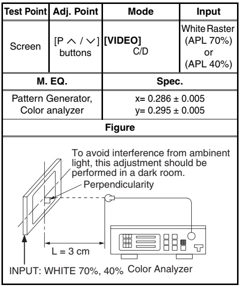
3. Set the color analyzer to the CHROMA mode and bring the optical receptor to the center on the LCD-Panel surface after zero point calibration as shown below.
Note: The optical receptor must be set perpendicularly to the LCD Panel surface.

4. Enter the Service mode. Press [Vol -] button on the service remote control unit and select “C/D” mode.
5.
[CUTOFF]
Press [3] button to select “COB” for Blue Cutoff adjustment. Press [1] button to select “COR” for Red Cutoff adjustment.
[DRIVE]
Press [6] button to select “DB” for Blue Drive adjustment. Press [4] button to select “DR” for Red Drive adjustment.
6. In each color mode, press [P-UP / DN ] buttons to adjust the values of color.
7. Adjust Cutoff and Drive so that the color temperature becomes 9200°K (x= 0.286 / y= 0.295 ±0.005).
8. Change the video signal input in step 2 and repeat from step 3.
HOW TO INITIALIZE THE LCD TELEVISION

1. Turn the power on.
2. To enter the service mode, press the service button on the service remote control unit.
- To cancel the service mode, Press [POWER ] button on the remote control unit.
3. Press [ i ] button on the service remote control unit to initialize the LCD television.
4. "INITIALIZED" will appear in the upper right of the screen. "INITIALIZED" color will change to green from red when initializing is complete.

Schematic diagrams


Wiring diagram


Saturday, 6 April 2019

SYLVANIA - FUNAI - LC195SL9 B - 19 INCH LCD TV - MAIN BOARD CIRCUIT DIAGRAM

SYLVANIA - FUNAI - LC195SL9 B - 19 inch LCD TV - Main board Circuit Diagram

MAIN DIGITAL BOARD SCHEMATIC

Saturday, 30 March 2019

FUNAI CTV S2900PF - SCHEMATIC (CIRCUIT DIAGRAM)

FUNAI CTV S2900PF - SCHEMATIC (Circuit Diagram)

STR-G9656 – TMP8827PSNG – ATM24C08 – TA8246 – TC90L01NFUNAI S-2900PF -  Color TV CIRCUIT DIAGRAM
SCHEMATIC [Circuit Diagram]
SMPS SECTION
CLICK ON THE SCHEMATICS TO ZOOM IN

KONKA LCD TV - LC32AS28 – LC26A2 - ILO CIWL2606 AND FUNAI 26 INCH LCD TVS - SMPS SCHEMATIC

KONKA LCD TV - LC32AS28 – LC26A2 - ILO CIWL2606 and Funai 26 inch LCD TVs - SMPS SCHEMATIC

Used ICs - OZ9932 – 6930A – LD7575 – CE3B1065 – DLA001 – UCC28051 – STP10 (Power MOSFET) – PC123Y82 (Photo-coupler) - 2SK3797 Power Switching FET (ILO - Funai)
ILO-CIWL2606 and FUNAI 26 Inch LCD TV SMPS
CLICK ON THE PICTURES TO MAGNIFY

FUNAI - 32FL553P-10 32FL553-10 - LED-LCD TV - SERVICE MODE – INITALIZATION – FIRMWARE UPDATE

FUNAI - 32FL553P-10 32FL553-10 - LED-LCD TV - SERVICE MODE – INITIALIZE – Firmware Update

How to enter Service Mode _ Initialize _ Firmware Update _ FUNAI 32FL553P-10 -  32FL553-10 _ 32˝ COLOR LED-LCD TELEVISION
SMPS (Main Power Regulator_ Schematic Diagram_PWB 
Used ICs Power Regulator Circuit: FA8A00N [Switching Control] _ TK5A65D [Switching MOSFET] x 2 _ TLP781F [Photo-coupler] _ MP2482DN-C447-LF-Z [+5V Regulator] _ FDD5612 [STB + 5V & for +13V Switching] _ HA7219PB [LED Back-light Driver]
Universal Remote Control Set-up Codes to check with FUNAI brand TVs [all types] - With Different brand remote controls
HOW TO ENTER SERVICE MODE
1. Turn the power on.
2. Press [SOURCE], [2], [5], [8] and [0] buttons on the remote control unit in this order to enter the service mode.
The Factory Setting menu appears in the screen.
HOW TO INITIALIZE
Turn the power on.
2. Enter the service mode.
> To cancel the service mode, press [BACK] button on the remote control unit.
3. Select “Factory Reset” and [OK] button on the remote control unit.  The TV set will go off and turn back on automatically when initialization completes.
HOW TO UPDATE THE FIRMWARE
1. Prepare USB storage device.
2. Copy F/W-file to USB storage device.  Note: Make sure to use the blank USB Storage.
3. Make sure that the F/W-file’s name is “LC11_308B_FUNAI.bin
Update procedure
1. Turn the power on.
2. Insert USB storage device with F/W to TV set.
3. Press the [MENU] button on the remote control unit to display Menu.
4. Select “SETUP”.
5. Select “Software Update (USB)” and press [OK] button.  
The message “Are you sure?” will appear in the screen.
6. Press [LEFT] button to select “YES”.
7. Updating starts.  Note: Do not turn off the TV set and do not remove the USB storage device while this procedure.
8. The TV set will go off and turn back on automatically when update completes.
Additional step:
A1. Enter the service mode.
A2. Select "Init TV" and press [OK] button.  The TV set will go off and go back on automatically.
A3. Adjust the white balance.
White Balance Adjustment
Purpose: To mix red and blue beams correctly for pure white.
Symptom of Maladjustment: White becomes bluish or reddish.
1. Operate the unit for more than 60 minutes.
2. Input the White Raster of composite video signal to AV (70%=70IRE, 40%=40IRE).
3. Enter the service mode.
4. Press [0] button on the remote control unit to display the “White Balance” menu.
Additional step:
A1. Press [2] button on the remote control unit to select the “Colour Temp” menu.
A2. Press [] or [] button to select the "Normal".
5. Select a color mode (“3 R-GAIN”, “5 B-GAIN”, “6 R-OFFSET” or “8 B-OFFSET”).
6. Set the color analyzer at the CHROMA mode and zero point calibration. Bring the optical receptor pointing at the center of the LCD-Panel.  Note: The optical receptor must be set perpendicularly to the LCD Panel surface.
7. In each color mode, press [ s] or [ B] button to adjust the color temperature becomes 12000°K (x= 0.272 / y= 0.278 ±0.002).
8. To cancel or to exit from the White Balance Adjustment, press [BACK] button.
SMPS CIRCUIT DIAGRAM
PWB - TOP & BOTTOM VIEW
  Because a hot chassis ground is present in the power supply circuit, an isolation transformer must be used when repairing.  Also, in order to have the ability to increase the input slowly, when troubleshooting this type of power supply circuit, a variable isolation transformer is required.
  Fixed voltage (or Auto voltage selectable) power supply circuit issued in this unit. If Main Fuse (F602) is blown, check to see that all components in the power supply circuit are not defective before you connect the AC plug to the AC power supply.  Otherwise it may cause some components in the power supply circuit to fail.
  For continued protection against fire hazard, replace only with the same type fuse.
UNIVERSAL REMOTE CONTROL SET-UP CODES
0042 0076 0094 0601 0616 0654 If your TV asks for a 3 digit code; just strike out the leading 'Zero' of each code; and check with it. For example, if the four digit code is 0601; you can make it as '601' (3-digit code) by deleting the leading zero.  Like-ways; you can check  all the other codes stated here..
CLICK ON THE PICTURES TO MAGNIFY

Friday, 29 March 2019

FUNAI LDD A2006 - TV-DVD COMBO - HOW TO ENTER SERVICE MODE - FIRMWARE UPDATE

FUNAI LDD A2006 - TV-DVD COMBO- HOW TO ENTER SERVICE MODE - FIRMWARE UPDATE

How to enter Service Mode_Firmware Update _ Initialize _  SMPS & Back-Light Inverter Schematics _  FUNAI 20 " LCD TV/DVD LDD-A2006 / LDD-B2006 / LDD-C2006 / LDD-D2006 Universal remote control set-up codes to Funai brand TVs
HOW TO INITIALIZE
DVD Section
* Press [1], [2], [3], [4], and [DISPLAY] buttons on the remote control unit in that order.
* Press [CLEAR] button on the remote control unit.
* When “OK” appears on the screen, the factory default will be set.
* To exit this mode, press [CH▲/▼] or [SELECT] button to go to TV mode, or press [STANDBY] button to turn the power off.
LCD TV SECTION
> Turn the power on. (Use main power on the TV unit.)
> To enter the service mode, press [STANDBY], [2], [7], [1], and [MUTE] buttons on the remote control unit in that order within 5 seconds. [To cancel the service mode, press [STANDBY] button on the remote control.]
> To initialize the LCD television, press “DISPLAY” button on the remote control unit.
> Confirm "FF" indication on the upper right of the screen.
FIRMWARE RENEWAL MODE
* Turn the power on and press [EJECT] button on the remote control unit to put the LCD TV/DVD into DVD mode. Then remove the disc.
* To put the LCD TV/DVD into F/W version up mode, press [9], [8], [7], [6], and [MODE] buttons on the remote control unit in that order.
* Insert the disc for version up into the disc slot.
* The LCD TV/DVD enters the F/W version up mode automatically. Fig. c appears on the screen. If you enter the F/W for different models, “Disc Error” will appear on the screen, then the disc will be ejected automatically.
* After programming is finished, the disc will be ejected automatically. [At this time, no button is available.]
* Remove the disc.
* Press [CH ▲/▼] button on the unit to go to TV mode, or press [STANDBY] button on the unit to turn the power off.
* Press [EJECT] button on the remote control unit to put the LCD TV/DVD into DVD mode again.
* Press [1], [2], [3], [4], and [DISPLAY] buttons on the remote control unit in that order.
* Press [CLEAR] button on the remote control unit.
* To exit this mode, press [CH▲/▼] or [SELECT] button to go to TV mode, or press [STANDBY] button to turn the power off.
SMPS & BACK-LIGHT INVERTER SECTION CIRCUIT DIAGRAM
Universal remote control set-up codes to check with Funai Brand TVs.
If your set asks for a 3 digit code, delete the leading Zero from each code and check.  For example; if the 4 digit code given here is '0601' and you need a 3 digit code out from it, enter '601' instead of 0601.  Like-ways; you can check with all other codes given here.
0042 0076 0094 0601 0616 0654
CLICK ON THE PICTURES TO MAGNIFY

Thursday, 28 March 2019

SYLVANIA LC195SL9 B – FUNAI LC195SL9 B – LCD TV – HOW TO ENTER SERVICE MODE – INITILIZATION

SYLVANIA LC195SL9 B – FUNAI LC195SL9 B – LCD TV – HOW TO ENTER SERVICE MODE – INITILIZATION

Power supply [SMPS], Backlight inverter Circuit diagrams – Connector pin voltages - Sylvania and Funai – LC195SL9B – 19 inch LCD TV
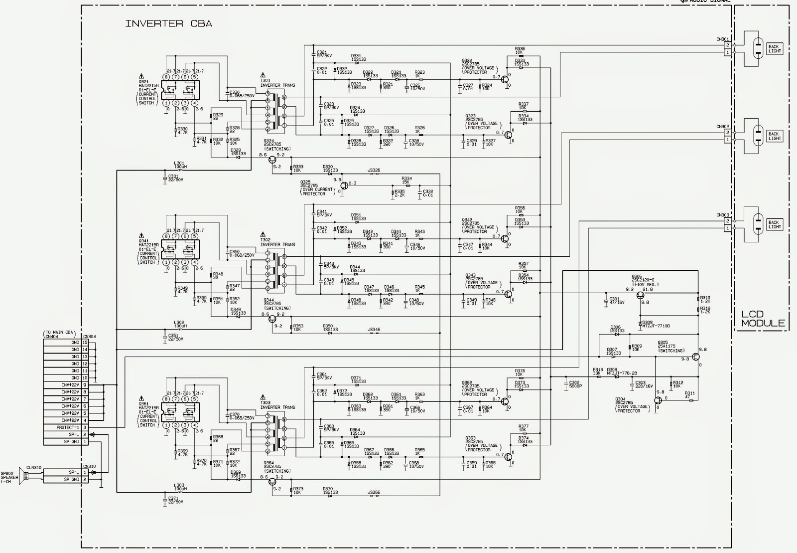
Used ICs: SA7412 – NJM4558M – PCM1782DBGR – TC4052BF – HAT2215R01-Current control switch at Inverter.
HOW TO ENTER SERVICE MODE
Use the service remote control unit.
Turn the power on.
Press the service button on the service remote control unit.
The following screen appears.
How to make the Service remote control unit
Cut “A” portion of the attached remote control unit as shown in above Fig
PURITY CHECK MODE
This mode cycles through full-screen displays of red, green, blue, and white to check for non-active pixels.
Enter the Service mode.
Each time pressing 7 button on the service remote control unit, the display changes as follows.
HOW TO INITIALIZE THE TV
> Turn the power on.
> To enter the service mode, press the service button on the service remote control unit. Press [INFO] button on the service remote control unit to initialize the LCD television.  "INITIALIZED" will appear in the upper right of the screen. "INITIALIZED" colour will change to green from red when initializing is complete.
[To cancel the service mode, press [POWER] button on the remote control unit.]
SMPS [Power supply regulator] board schematic

CONNECTOR VOLTAGES
BACK-LIGHT INVERTER CIRCUIT DIAGRAM
BACK-LIGHT INVERTER PWB - TOP & FOIL SIDE VIEW
CLICK ON THE PICTURES TO MAGNIFY