HCL and Samsung 15 Inch LCD monitor – How to enter the service mode – adjustments – Power and backlight inverter Schematic
HCL
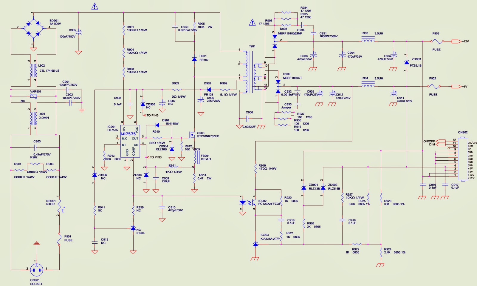
HCMDLWBT21 - HCMDLWBN21 - Samsung 15 inch monitor – Power (SMPS) and Back-light
inverter – Circuit Diagram – Service Mode and adjustments
Press
the MENU button, pull out the power cord, and then plug the power cord. Then
the factory OSD will be at the left top of the panel.
White- Balance, Luminance Adjustment
Approximately
30 minutes should be allowed for warm up before proceeding white
balance adjustment. Before started adjust white balance , please set the
Chroma-7120 MEM Channel 3 to Warm (6500K) color, MEM Channel 4 to
Normal (7300K) color, MEM Channel 9 to Cool (9300K) color , and MEM
Channel 10 to sRGB color ( our Warm color parameter is x = 313 ±30, y =
329 ±30, Y>140cd/m2; Normal color parameter is x = 302 ±30, y = 318
±30, Y>130cd/m2; Cool color parameter is x = 283 ±30, y = 297 ±30,
Y>110cd/m2; sRGB color parameter is x = 313 ±30, y = 329 ±30,
Y>140cd/m2).
How
to setting MEM channel you can reference to chroma 7120 user guide or
simple use “ SC” key and “ NEXT” Key to modify xyY value and use “ID”
key to modify the TEXT description Following is the procedure to do white-balance adjust.
Setting the color temp. you want
A. MEM.CHANNEL 3 (Warm color):
Warm color temp. parameter is x = 313 ±30, y = 329 ±30, Y>140cd/m2
B. MEM.CHANNEL 4 (Normal color):
Normal color temp. parameter is x = 302 ±30, y = 318 ±30, Y>130cd/m2
C. MEM.CHANNEL 9 (Cool color):
Cool color temp. parameter is x = 283 ±30, y = 297 ±30, Y>110cd/m2
D. MEM.CHANNEL 10 (sRGB color):
sRGB color temp. parameter is x = 313 ±30, y = 329 ±30, Y>140cd/m2
Into Factory mode.
Press the MENU button, pull out the power cord, and then plug the power cord.
Then the factory OSD will be at the left top of the panel.
Bias adjustment:
Set the Contrast to 50; Adjust the Brightness to 80.
Gain adjustment:
Move cursor to “-F-” and press MENU key.
A. Adjust Warm (6500K) color-temperature
1. Switch the chroma-7120 to RGB-Mode (with press “MODE” button)
2. Switch the MEM.channel to Channel 3 (with up or down arrow on chroma 7120)
3. The LCD-indicator on chroma 7120 will show x = 313 ±30, y = 329 ±30, Y>140cd/m2
4. Adjust the RED on factory window until chroma 7120 indicator reached the value R=100
5. Adjust the GREEN on factory window until chroma 7120 indicator reachedthe value G=100
6. Adjust the BLUE on factory window until chroma 7120 indicator reached the value B=100
7. Repeat above procedure (item 4, 5, 6) until chroma 7120 RGB value meet the tolerance =100±2
B. Adjust Normal (7300K) color-temperature
1. Switch the chroma-7120 to RGB-Mode (with press “MODE” button)
2. Switch the MEM.channel to Channel 4(with up or down arrow on chroma 7120)
3. The LCD-indicator on chroma 7120 will show x = 302 ±30, y = 318 ±30, Y>130cd/m2
4. Adjust the RED on factory window until chroma 7120 indicator reached the value R=100
5. Adjust the GREEN on factory window until chroma 7120 indicator reachedthe value G=100
6. Adjust the BLUE on factory window until chroma 7120 indicator reached the value B=100
7. Repeat above procedure (item 4, 5, 6) until chroma 7120 RGB value meet the tolerance =100±2
C.
Adjust Cool (9300K) color-temperature
1. Switch the Chroma-7120 to RGB-Mode (with press “MODE” button)
2. Switch the MEM. Channel to Channel 9 (with up or down arrow on chroma 7120)
3. The LCD-indicator on chroma 7120 will show x = 283 ±30, y = 297 ±30,
Y>110cd/m2
4. Adjust the RED on factory window until chroma 7120 indicator reached the
value R=100
5. Adjust the GREEN on factory window until chroma 7120 indicator reached the
value G=100
6. Adjust the BLUE on factory window until chroma 7120 indicator reached the
value B=100
7. Repeat above procedure (item 4, 5, 6) until chroma 7120 RGB value meet the
tolerance =100±2
D.
Adjust sRGB color-temperature
1. Switch the chroma-7120 to RGB-Mode (with press “MODE” button)
2. Switch the MEM.channel to Channel 10 (with up or down arrow on chroma 7120)
3. The LCD-indicator on chroma 7120 will show x = 313 ±30, y = 329 ±30,
Y>140cd/m2
4. Adjust the RED on factory window until chroma 7120 indicator reached the
value R=100
5. Adjust the GREEN on factory window until chroma 7120 indicator reachedthe value
G=100
6. Adjust the BLUE of on factory window until chroma 7120 indicator reached the
value B=100
7. Repeat above procedure (item 4, 5, 6) until chroma 7120 RGB value meet the
tolerance =100±2
E. Turn the Power-button off to quit from factory mode.
715G2852-2 SMPS board Circuit Diagram (Schematic) and PWB
Back Light inverter schematic
Click on the pictures to zoom in
 HCL HCM9LWAT11 - 19 INCH LCD MONITOR – POWER SUPPLY SCHEMATIC [Circuit Diagram] - No Power - Troubleshooting