REPAIRING AND NOT THROWING AWAY

Richtige Fernseher haben Röhren!

Richtige Fernseher haben Röhren!

In Brief: On this site you will find pictures and technical information about Service Modes, Circuit Diagrams, Firmware Update procedure, Disassemble procedure, Universal remote control set-up codes, Troubleshooting and more....

If you go into the profession, you will obtain or have access to a variety of tech tips databases HERE IT IS Master Electronics Repair !.

These are an excellent investment where the saying: 'time-is-money' rules. However, to learn, you need to develop a general troubleshooting approach - a logical, methodical, method of narrowing down the problem. A tech tip database might suggest: 'Replace C536' for a particular symptom. This is good advice for a specific problem on one model. However, what you really want to understand is why C536 was the cause and how to pinpoint the culprit in general even if you don't have a service manual or schematic and your tech tip database doesn't have an entry for your sick TV or VCR.

While schematics are nice, you won't always have them or be able to justify the purchase for a one-of repair. Therefore, in many cases, some reverse engineering will be necessary. The time will be well spent since even if you don't see another instance of the same model in your entire lifetime, you will have learned something in the process that can be applied to other equipment problems.
As always, when you get stuck, checking out a tech-tips database may quickly identify your problem and solution.In that case, you can greatly simplify your troubleshooting or at least confirm a diagnosis before ordering parts.

Happy repairing!
Today, the West is headed for the abyss. For the ultimate fate of our disposable society is for that society itself to be disposed of. And this will happen sooner, rather than later.

How to use the site:

- If you landed here via any Search Engine, you will get what you searched for and you can search more using the search this blog feature provided by Google. You can visit more posts scrolling the left blog archive of all posts of the month/year,
or you can click on the main photo-page to start from the main page. Doing so it starts from the most recent post to the older post simple clicking on the Older Post button on the bottom of each page after reading , post after post.

You can even visit all posts, time to time, when reaching the bottom end of each page and click on the Older Post button.

- If you arrived here at the main page via bookmark you can visit all the site scrolling the left blog archive of all posts of the month/year pointing were you want , or more simple You can even visit all blog posts, from newer to older, clicking at the end of each bottom page on the Older Post button.
So you can see all the blog/site content surfing all pages in it.

- The search this blog feature provided by Google is a real search engine. If you're pointing particular things it will search IT for you; or you can place a brand name in the search query at your choice and visit all results page by page. It's useful since the content of the site is very large.

Note that if you don't find what you searched for, try it after a period of time; the site is a never ending job !

..............The bitterness of poor quality is remembered long after the sweetness of todays funny gadgets low price has faded from memory........ . . . . . .....
Don't forget the past, the end of the world is upon us! Pretty soon it will all turn to dust!

©2010, 2011, 2012, 2013, 2014 Frank Sharp - You do not have permission to copy photos and words from this blog, and any content may be never used it for auctions or commercial purposes, however feel free to post anything you see here with a courtesy link back, btw a link to the original post here , is mandatory.
All posts are presented here for informative, historical and educative purposes as applicable within fair use. NOTHING HERE IS FOR SALE !

Showing posts with label HIFI. Show all posts

Saturday, 14 December 2019

HARMAN KARDON CD91 CIRCUIT DIAGRAM AND EXPLODED VIEW WITH COMPONENT LIST. CASSETTE DECK MECHANISM EXPLODED VIEW

Ultrawideband Linear Phase Cassette Deck – Harman Kardon CD91 circuit diagram and exploded view with component list.
Cassette Deck mechanism exploded view
Exploded view
Schematic [circuit diagram]
Wiring diagram

PANASONIC SA PM86 DVD STEREO SYSTEM HOW TO ENTER THE SERVICE MODE, FIRMWARE UPDATE, POWER AMP AND POWER SUPPLY SCHEMATIC, SYSTEM RESET

Panasonic SA PM86 DVD stereo system how to enter the service mode, firmware update, power amp and power supply schematic, system reset


Panasonic SA-PM86DGCS, SA-PM86DEE DVD Stereo System
This model’s mechanism unit is DLS6
RMS Output Power THD 10%  80 W per channel (3 Ω), 1 kHz
Total RMS Dolby Digital Mode  80 W per channel (3 Ω), 1 kHz
PMPO Output Power  1800 W
Speakers: SB-PM86EG-K
Video system PAL625/50, PAL525/60, NTSC
Power consumption 95 W AC 230 V, 50 Hz (EE) - AC 220 to 240 V, 50/60 Hz (GCS)
Before Repair and Adjustment Disconnect AC power, discharge Power Supply Capacitors C2207, C2210, C2211, C2212, C2742, C5105, C5106, C5916, C5917,
C5938, C5562, C5954, C5979 and C5993 through a 10Ω, 1W resistor to ground.  DO NOT SHORT-CIRCUIT DIRECTLY (with a screwdriver blade, for instance), as this may destroy solid state devices.
After repairs are completed, restore power gradually using a variac, to avoid over current.
Current consumption at AC 220 - 240 V, at 50/60 Hz in NO SIGNAL mode (at volume min) should be ~500 mA. (GCS)
Current consumption at AC 230 V 50 Hz in NO SIGNAL mode (at volume min) should be ~500 mA. (EE)
Protection
The protection circuitry may have operated if either of the following conditions are noticed:
• No sound is heard when the power is turned on.
• Sound stops during a performance.
The function of this circuitry is to prevent circuitry damage if, for example, the positive and negative speaker connection wires are "shorted", or if speaker systems with an impedance less than the indicated rated impedance of the amplifier are used.
If this occurs, follow the procedure outlines below:
1. Turn off the power.
2. Determine the cause of the problem and correct it.
3. Turn on the power once again after one minute.
Note:
When the protection circuitry functions, the unit will not operate unless the power is first turned off and then on again.
Do not disassemble the pickup unit, since radiation from exposed laser diode is dangerous.
2. Do not adjust the variable resistor on the pickup unit. It was already adjusted.
3. Do not look at the focus lens using optical instruments.
4. Recommend not to look at pickup lens for a long time
Service Mode
The service modes can be activated by pressing various button combination on the main unit and remote control unit.
Below is the summary for the various modes for checking
An error code will be canceled if a power supply is turned OFF.
1: CPPM is the copy guard function beforehand written in the disk for protection of copyrights.
2: CEC is the consumer electronic control used for high-level user control of HDMI-connected devices.
3: HDCP is the specification developed to control digital audio & video contents transmission for DVI or HDMI connections
By pressing various button combinations on the main unit and remote control unit, you can activate the various service modes for checking.
Due to the limitations of the no. characters that can be shown on the FL Display, the “FL Display” button on the remote control unit can be used to show the two display pages. (Display 1 / Display 2).
Optical Pick-up Self-Diagnosis
The optical pickup self-diagnosis function and tilt adjustment check function have been included in this unit. When repairing, use the following procedure for effective self-diagnosis and tilt adjustment. Be sure to use the self-diagnosis function before replacing the optical pickup when "NO DISC" is displayed. As a guideline, you should replace the optical pickup when the value of the laser drive current is more than the specified value.
[Press the power button to turn on the power, and check the value within three minutes before the unit warms up. (Otherwise, the result will be incorrect.)]
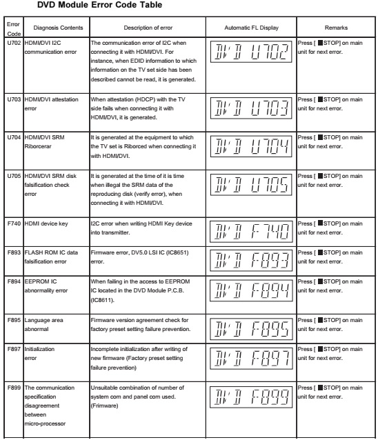
DVD Self Diagnostic Function-Error Code
Sales Demonstration Lock Function
This function prevents discs from being lost when the unit is used for sales demonstrations by disabling the disc eject function.
"LOCKED" is displayed on the unit, and ordinary operation is disabled.
Prohibiting removal of disc
1. Select the DVD/CD function.
2. At POWER ON condition, press and hold down the STOP button and the power button on the main unit for at least three seconds. (The message, “LOCKED” appears when the function is activated.)
[OPEN/CLOSE button is invalid and the main unit displays “LOCKED” while the lock function mode is entered]
Prohibiting operation of selector and disc
1. Select the DVD/CD function.
2. At POWER ON condition, press and hold down the PLAY button and the power button on the main unit for at least three seconds. (The message, “LOCKED” appears when the function is activated.)
The lock can be cancelled by the same procedure as used in setting. ("UNLOCKED" is displayed on cancellation. Disconnecting the power cable from power outlet does not cancel the lock.)
Recovery after the DVD player is repaired
• When the FLASH ROM IC or DVD Module P.C.B. is replaced, carry out the recovery processing to optimize the drive.  Playback the recovery disk to process the recovery automatically.
• Recovery disc (Product number: RFKZD03R005) [SPG]
• Performing recovery process
1. Load the recovery disc RFKZD03R005 on to the player and run it.
2. Recovery is performed automatically. When it is finished, a message appears on the screen.
3. Remove the recovery disc.
4. Turn off the power.
5. Initialize the player.
Firmware version-up of the DVD player
• The firmware of the DVD player may be renewed to improve the quality including operability and playability to the substandard discs. Processing to optimize the drive.
The recovery disc has also firmware version-up.
• After version-up, recovery processing is executed automatically.
• Part number of the recovery disc for version-up will be noticed when it is supplied.
• Updating firmware
1. Load the recovery disc on to the player and run it.
2. Firmware version of the player is automatically checked. Appropriate message appears whenever necessary.
3. Using remote controller´s cursor key, select whether version updating is to be done or not. (Selection of Yes/No)
4. a. If Yes is selected, version updating is performed.
b. If No is selected, only recovery is performed.
5. a. When updating is finished, remove the disc according to the message appearing on the screen.
b. Remove the disc according to the message appearing on the screen.
6. Turn off the power.
 [If the AC power supply is shut out during version-up due to a power failure, the version-up is improperly carried out.  In such a case, replace the FLASH ROM IC and carry out the version-up again.]
DVD Module P.C.B. Reset
• When after replacing FLASH ROM IC or DVD Module P.C.B., FL displays error code “ DVD F897”. This means the unit is not initialized properly and the following process needs to be carry out.
• Procedures:
1. Press _>10 on remote control while pressing “STOP” button on main unit. (To enter into initialization)
2. FL display show “INIT”
3. While still pressing “STOP” button on main unit, press “OK” on remote control. (To reset the unit)
4. FL will display “RESET” before FL display will change to TOC reading again.
5. Power off unit. Unplug the AC cord.
6. Power on the unit. It should be no problem. If problem persist check on the DVD Module P.C.B. or FLASH ROM IC.

Power amplifier and main power schematic


Power clamp circuit
Power Transformer circuit

Saturday, 16 March 2019

SONY - HCD D670AV – HCD N555AV - DISASSEMBLY PROCEDURE

SONY - HCD D670AV – HCD N555AV - DISASSEMBLY PROCEDURE


FRONT PANEL ASS'Y AND MAIN BOARD 
CLICK ON THE PICTURES TO ZOOM. Click ß at the top of the browser to come back.
MECHANISM DECK
CD MECHANISM DECK
BU BRACKET ASS'Y
DISC TABLE

Tuesday, 12 March 2019

DENON DN-X1500 - DN-X1500S DISASSEMBLING AND SERVICE MODE

DENON DN-X1500 - DN-X1500S DISASSEMBLING AND SERVICE MODE


DENON DN-X1500 - DN-X1500S DJ MIXER DISASSEMBLING SERVICE MODE AND POWER SUPPLY CIRCUIT  


DISASSEMBLING  (Follow the procedure below in reverse order when reassembling.) 1. Top Panel Unit (1) Remove 9 side screws and pull up the Top Panel Unit. (2) Disconnect FFC cable and Connector. (3) Detach Top Panel Unit Note : Do not pull out aslant to prevent FFC cable damage. Do not fail to pull AC cord from wall outlet before disconnect the FFC cable. If AC cord is remained plugged into wall outlet, power is kept supplied in the unit, which may cause danger.

2. Cross Fader Unit
(1) Remove 2 top screws and pull up Cross Fader Unit.
(2) Disconnect Connector.

3. CH Fader Unit
(1) Remove 4 knobs.
(2) Remove 4 screws and pull up CH Fader Panel.
(3) Remove 2 screws for each CH.
(4) Disconnect Connector.
(5) Detach CH Fader Unit.

4. Top Panel
(1) Pull out the knobs.
(2) Remove 8 screws.
(3) Detach Top Panel.

ADJUSTING THE MOVEMENT OF THE CROSS FADER CONTROL
(1) Move the Cross Fader control all the way to the end in the direction of the arrow.
(2) Turn Cross Fader screw A gently using the adjustment screwdriver to adjust the movement of the control. When turned clockwise, the movement of the control becomes heavier. When turned counterclockwise, the movement of the control becomes lighter.
(3) After adjusting, mount the Cross Fader Unit onto the main unit, being sure to place the cable properly. Be careful not to let the cable get stuck in the main unit.
Note : The Cross Fader has a precision structure. Do not tighten or loosen it excessively. Doing so could cause malfunction or adversely affect performance.

SERVICE MODE 
Power on while pressing MIC POST ON/OFF button and EFFECT LOOP ON/OFF button.
For canceling the service mode, turn power off/on
POWER SUPPLY CIRCUIT 
CLICK ON THE IMAGE TO ZOOM IN

MCINTOSH MC2000 CIRCUIT

MCINTOSH MC2000 CIRCUIT

MCINTOSH MC2000

CIRCUIT

Power Output
130 watts into 8, 4 or 2 ohm loads is the minimum sine wave continuous average power output per channel from 20Hz to 20,000Hz with both channels operating.
Power Requirement
100 Volts, 50/60Hz at 5.8 Amps
120 Volts, 50/60Hz at 4.8 Amps
230 Volts, 50/60Hz at 2.5 Amps
ABOUT SCHEMATIC
. The heavy lines on the schematics denote the primary signal path.
2. Unless otherwise noted, all voltages indicated on the schematics are measured under the following conditions:
a. AC input at 120 volts, 50/60Hz
b. All voltages are +/-10% with respect to ground.
A high impedance (10megaohm) voltmeter must be used.
3. Unless otherwise specified:
a. Resistors values are in ohms.
b. Capacitor values are in microfarads (uF).
c. Inductor values are in microhenries (uH).
4. On PC Board Drawings, Square Pad Indicates:
a. Polarized Capacitors - Positive
b. Diode - Cathode
c. Others - Pin 1
POWER AMP CIRCUIT 

VU METER CIRCUIT 
CLICK O THE IMAGES TO ZOOM IN


VU METER COMPONENT LIST
ZENERDIODE 6.2V 5% 500MW D12
DIODERECTIFIERD2 D11
FUSE 2ASLO-BLO 5 X 20 250VIEC F1
MALECONN 3 POS RT ANGLEJ2-
MALECONN 6 PIN RT ANGLEJ1-
4 PIN RT.ANGLEJ3-
TRIAC8A 200VQ8
TRANSISTOR NPN MPS4124 2K/REEL Q1 Q5
TRANSISTOR PNPQ2 Q6
TRANSISTOR P.CHANNEL JUNC.FET Q7
TRANSISTOR NPNQ3 Q4
ICREGULATOR -12VIC2
ICREGULATOR 12VIC1
DUALOPERATIONAL AMPLIFIER IC3 IC4
TRIM POT100K OHM 20%R10
RES CF3.3K 5% 1/4WR23
RES CF2.7M 5% 1/4WR1
RES CF10 5% 1/4WR26
CARB FILMRES 680 OHMS 5% 1/2W R24
RES MF10K 1% 1/4WR7 R20 R22
RESMF10K 1% 1/4WR7 R22
MF 499 OHMSR17
METALFILM RES 1K 1% 1/4WR19 R25
16.5K 1% 1/4WR18
METALFILM RES 200K 1% 1/4W R6 R12
METALFILM RES 150K 2% 1/4W R9
METALFILM RES 22.1K 1% 1/4W R21
METALFILM RES 100 OHM 1% 1/4W R11 R16
METALFILM RES 10M 1% 1/4W R8
METALFILM RES 1M 1/4WR2
METALFILM RES 2.74M OHM 1/4WR13
MF RES3.92K 1% 1/4WR15
MF RES15K 1% 1/4WR5 R14
MF RES13.7K 1% 1/4WR20

MCINTOSH MA6900 TONE CONTROL CIRCUIT

MCINTOSH MA6900 TONE CONTROL CIRCUIT

MCINTOSH MA6900

TONE CONTROL CIRCUIT 

TONE COTROL COMPONENTS
C1 C2  CAP M POLY .1UF 10% 100VDC
C3 C4  CAP ELECT 10UF 16V (4X5 CASE)
C5 C6  CAP MONO 220PF 100V 10% NPO
C7 C8  CAP MONO 47PF 200V 10% NPO
C9 C10  CAP MONO 22PF 200V 10% NPO
C11 C12  CAP ELECT 220UF 25V
C13 C14 C33 C34  CAP ELECT 47UF 50V
C15 C16 C43 C44 C45 C46 C54  CAP ELECT 10UF 50V
C17 C18  CAP M POLY .047UF 5% 63VDC
C19 C20  CAP ELECT 1.5UF 10% 50V
C21 C22  CAP M POLY .01UF 5% 63VDC
C23 C24  CAP M POLY .47UF 5% 50/63VDC
C25 C26  CAP MPOLY .0033UF 5% 63VDC
C27 C28  CAP M POLY .15UF 5% 63VDC
C29 C30  CAP POLY 0.001MF 5% 63VDC
C31 C32  CAP M POLY .033UF 5% 63VDC
C35 C36 C37 C38  CAP M POLY .22UF 5% 63VDC
C39 C40 C41 C42  CAP MONO 470PF 100V 10% NPO
C47 C48 C49 C50 C51 C52  CAP MONO .1UF 50V 20% Z5U
C53  CAP ELECT 47UF 10V BP
D1 D2  DIODE SILICON
IC1 IC6 IC7  IC DUAL OPERATIONAL AMPLIFIER
IC2 IC3 IC4 IC5  IC OPERATIONAL AMPLIFIER
J1  CONN 8 POS MALE FRICTION LOCK
J2  CONN 4 PIN
J3  CONN MALE 6 POS RT ANGLE
K1 K2 K3  RELAY REED FORM 1A 5V 500 OHMS
R1  POT 50KAX2
R2  POT BALANCE 2KOHM
R3 R4 R5 R6 R7  POT EQUAL
R9 R10  RES MF 2.21K 1% 1/4W
R11 R12  RES MF 3.32K 1% 1/4W
R13 R14  RES MF 475K 1% 1/4W
R15 R16 R19 R20  RES MF 1K 1% 1/4W
R17 R18  RES MF 10K 1% 1/4W
R21 R22 R45 R46  RES MF 2.74K 1% 1/4W
R23 R24 R27 R28 R31 R32 R35 R36  RES MF 681 1% 1/4W
R25 R26R29 R30 R33 R34 R37 R38 R43  RES MF 100K 1% 1/4W
R39 R40  RES MF 475 1% 1/4W
R41 R42  RES MF 40.2K 1% 1/4W
R44 R51 R52  RES MF 100K 1% 1/4W
R47 R48  RES MF 33.2K 1% 1/4W
R49 R50  RES MF 22.1 1% 1/4W
R53 R54  RES MF 100 1% 1/4W
R55 R56 R57 R58  RES MF 10 1% 1/4W
CIRCUIT DIAGRAM 
CLICK ON THE IMAGE TO ZOOM IN

Monday, 4 March 2019

PANASONIC COMPACT STEREO SYSTEM SC-HC3P - SC-HC3PC - SERVICE MODE - ERROR CODES - SMPS AND AMPLIFIER SCHEMATIC

Panasonic Compact Stereo System SC-HC3P - SC-HC3PC - Service Mode - Error Codes - SMPS and Amplifier Schematic

Service mode – Self Diagnostic function – Error Codes – SMPS and Output Amplifier Circuit diagram - How to take out the disc in emergency - Panasonic SC HC3P - Compact Stereo System
Speaker unit(s) => Full range 6.5 cm Cone type Impedance 6Ohms
Input power (IEC) 30 W (Max) - Output sound pressure 79 dB/W (1.0m)
Frequency range 55 Hz to 25 kHz (-16 dB) 90 Hz to 22 kHz (-10 dB)
Power supply AC 120 V, 60 Hz
Power consumption 28 W
Amplifier Section
RMS Output Power Stereo Mode
Front Ch (both ch driven) 20 W per channel (6 Ω), 1 kHz, 10% THD
Self diagnosis and special mode setting
Service Mode
The service modes can be activated by pressing various button combinations on the main unit and remote control unit.  Below is the summary for the various modes for checking
Service Mode Table 1
Service Mode Table 2
Error Code Table
Self-Diagnosis Function provides information on any problems occurring for the unit and its respective components by displaying error codes. These error code such as U**, H** and F** are stored in memory and held unless it is cleared.  The error code is automatically display after entering into self-diagnostic mode.
CD Door Unit Jam - Removing the CD
Insert a flat-head screwdriver into the hole behind the CD Door Unit and push the gear fixture from point A to B.
Push the CD Door Unit as arrow shown until the CD is fully in sight.
Remove the CD.
D-Amp Circuit Diagram
SMPS Circuit Diagram & PWB
Click on the pictures to zoom in