REPAIRING AND NOT THROWING AWAY

Richtige Fernseher haben Röhren!

Richtige Fernseher haben Röhren!

In Brief: On this site you will find pictures and technical information about Service Modes, Circuit Diagrams, Firmware Update procedure, Disassemble procedure, Universal remote control set-up codes, Troubleshooting and more....

If you go into the profession, you will obtain or have access to a variety of tech tips databases HERE IT IS Master Electronics Repair !.

These are an excellent investment where the saying: 'time-is-money' rules. However, to learn, you need to develop a general troubleshooting approach - a logical, methodical, method of narrowing down the problem. A tech tip database might suggest: 'Replace C536' for a particular symptom. This is good advice for a specific problem on one model. However, what you really want to understand is why C536 was the cause and how to pinpoint the culprit in general even if you don't have a service manual or schematic and your tech tip database doesn't have an entry for your sick TV or VCR.

While schematics are nice, you won't always have them or be able to justify the purchase for a one-of repair. Therefore, in many cases, some reverse engineering will be necessary. The time will be well spent since even if you don't see another instance of the same model in your entire lifetime, you will have learned something in the process that can be applied to other equipment problems.
As always, when you get stuck, checking out a tech-tips database may quickly identify your problem and solution.In that case, you can greatly simplify your troubleshooting or at least confirm a diagnosis before ordering parts.

Happy repairing!
Today, the West is headed for the abyss. For the ultimate fate of our disposable society is for that society itself to be disposed of. And this will happen sooner, rather than later.

How to use the site:

- If you landed here via any Search Engine, you will get what you searched for and you can search more using the search this blog feature provided by Google. You can visit more posts scrolling the left blog archive of all posts of the month/year,
or you can click on the main photo-page to start from the main page. Doing so it starts from the most recent post to the older post simple clicking on the Older Post button on the bottom of each page after reading , post after post.

You can even visit all posts, time to time, when reaching the bottom end of each page and click on the Older Post button.

- If you arrived here at the main page via bookmark you can visit all the site scrolling the left blog archive of all posts of the month/year pointing were you want , or more simple You can even visit all blog posts, from newer to older, clicking at the end of each bottom page on the Older Post button.
So you can see all the blog/site content surfing all pages in it.

- The search this blog feature provided by Google is a real search engine. If you're pointing particular things it will search IT for you; or you can place a brand name in the search query at your choice and visit all results page by page. It's useful since the content of the site is very large.

Note that if you don't find what you searched for, try it after a period of time; the site is a never ending job !

..............The bitterness of poor quality is remembered long after the sweetness of todays funny gadgets low price has faded from memory........ . . . . . .....
Don't forget the past, the end of the world is upon us! Pretty soon it will all turn to dust!

©2010, 2011, 2012, 2013, 2014 Frank Sharp - You do not have permission to copy photos and words from this blog, and any content may be never used it for auctions or commercial purposes, however feel free to post anything you see here with a courtesy link back, btw a link to the original post here , is mandatory.
All posts are presented here for informative, historical and educative purposes as applicable within fair use. NOTHING HERE IS FOR SALE !

Showing posts with label IC. Show all posts

Friday, 15 March 2019

AKIRA 14PHS3 WITH TDA-9381 - _SERVICE MODE ENTRY

AKIRA 14PHS3 WITH

TDA-9381 - _SERVICE MODE ENTRY

TO ENTER FACTORY MODE [SERVICE MODE]

  • Press the "Menu"
  • When the Picture Menu [Brightness & Contrast] reveals,
  • Enter code "8500"
Factory mode adjustment screen appears. 
Use Up /Dn & Right / Left buttons on the remote control to Select and adjust any item; and to change the data values.
Switch off the Main Power, to exit the service mode.
Some of the factory data is fixed, and cannot be adjustable.

Wednesday, 27 February 2019

HOW TO ENTER SERVICE MODE TO SANYO TV [ USING IC LC863528C ] - MAIN SYSTEM CONTROL

DATA IC LA76818A Dan LC863528C TV China HOW TO ENTER SERVICE MODE TO SANYO TV [ USING IC LC863528C ] - MAIN SYSTEM CONTROL

To enter the service mode to these sets,

Press [Sleep] button on the remote handset, and [Menu] button on the front panel of the TV at the same time.

To call an item to adjust, use [prog+ / prog--ve] keys.
To change the data value to selected item, press [Vol+ / Vol--ve] keys.
To exit from service mode, press [Sleep] button on the remote control.


LA76818A

 DATA / PIN :


  1 = AUDIO OUT
  2 = FM OUT
  3 = PIF AGC
  4 = RF AGC
  5 = VIF IN 1
  6 = VIF IN 2
  7 = GRND (1F)
  8 =  VCC (VIF)
  9 = FM FIL
DATA IC LA76818A Dan LC863528C China 10 = AFT OUT
11 = DATA
12 = CLOCK
13 = ABL
14 = R IN
15 = G IN
16 = B IN
17 = BLANK IN
18 = VCC (RGG)
19 = R OUT
20 = G OUT
21 = B OUT
22 = SD
23 = V OUT
24 = RAMP ALC FIL
25 = VCC (H)

26 = H AFC FIL
27 = H OUT

28 = FBP IN
29 = VCO IREF
30 = CLOCK OUT
31 = VCC (CCD)
32 = CCD FIL
33 = GRND (CCD/H)
34 = SECAM B-Y IN
35 = SECAM R-Y IN
36 = APC2 FIL
37 = FSC OUT
38 = XTAL
39 = APC1 FIL
40 = SEL VIDEO OUT
41 = GRND (V/C/B)
42 = EXT VIDEO IN
43 = VCC (V/C/D)
44 = INT VIDEO IN
45 = BLK STREYCN FIL
46 = VIDEO OUT
47 = APC FIL
48 = VCO COIL
49 = VCO COIL
50 = VCO FIL
51 = EXT AUDIO IN
52 = SIF OUT
53 = SIN APC FIL
54 = SIF IN  


LC863528C

DATA / PIN :

  1 = UHF
  2 = 50/60
  3 = SDAO
  4 = SCLO
  5 = GRND
  6 = XTL 1
  7 = XTL 2
  8 = VDD
  9 = KEY IN
DATA IC LA76818A Dan LC863528C China
10 = AFT IN
11 = P 16:9
12 = S-VIDEO
13 = RESET
14 = FILTER
15 = POWER
16 = LNA (YUV)
17 = V-SYNC
18 = H-SYNC
19 = R
20 = G
21 = B
22 = BLANK
23 = MUTE
24 = SIF
25 = ENABLE
26 = SECAM
27 = SD
28 = IR
29 = VOL-R
30 = VOL-L
31 = WOOFER
32 = VT
33 = AV 2
34 = AV 1
35 = BAND 2 (VH)
36 = BAND 1 (VL)

Saturday, 23 February 2019

HOW TO ENTER THE SERVICE MODE OF TVS USING TDA11105, TDA11115, TDA11145, TDA12165 MICRO-JUNGLE IC, AND SERVICE MODE ADJUSTMENTS

How to enter the service mode of TVs using TDA11105, TDA11115, TDA11145, TDA12165 Micro-jungle IC, and service mode adjustments.


UOC-TOP configuration instructions: NT11106PC201AG
In the following NXP or Trident Micro-Jungle: 
TDA11105PS, TDA11106PS, TDA11115PS, TDA11126PS, TDA11145PS, TDA12135PS, TDA12136PS, TDA12165PS, TDA12196PS
Technical description
Introduction to UOC-TOP technology (series TDA11106PS)
The TDA11106PS / N2 series mainly adopts the form of pin package SDIP64 With the following:
* 200 channels in memory
* Image processing includes brightness control, contrast control, control color, system color control, image enhancement and five image modes.
* Users can edit the LOGO, show the LOGO when starting up and without signal
* Have the perpetual calendar and the game function.
* New OSD style, compatible with English, Thai, Vietnamese, Indonesian, Persian, Turkish, French, Bulgarian, Russian, Portuguese, Roman, Spanish, Italian, German, Dutch, Swedish, Norwegian, Hungarian, Polish, Czech, Slovenian, Croatian, Macedonian, Serbian, Greek, Kenyan
* Compatible with the FS and VS tuner
* With the screen change function, the up and down mode, and the left mode and Right is optional.
* The AKB function of all products is optional. When AKB is disabled, the energy in the cost of use can be reduced
* Added the left and right line suppression setting for an easy configuration of different parameters of the image tube
* Added CORING and the black extension in the image processing, obviously the image quality is improved.
Description of IC pins
Chip peripheral controller TDA11106 PS: EEPROM: 24C08
Remote control IC: NEC code / SANYO code. The factory debug instructions.
 How to enter the Factory mode (Service Mode)
Method 1: In normal use, press the [MENU] key, the menu is displayed "Image". 
When it is displayed, press the numeric keys "6, 4, 8, 3" in sequence and the television enters the factory mode.
Method 2: Use the [PROOF] button on the factory-specific remote control:
Remote control of the NEC code, press the [PRESET] key first, then press the [TEST] key within 2 second. 
The TV enters production mode and the screen shows the production mode indicator.
Remote control of the SANYO code, press the [TEST] button.
The TV enters production mode, display screen, show tips for the mode of production.
Press [TEST] or [POWER] to switch from production mode to status normal work.
Press [- / - -] in the [PROOF] state to enter the [BUS OPEN] state.
Under [BUS OPEN], press the [- / - -] key to return to the factory state.
Enter the debug / configure menu method
* User debugging menu: press the [TEST] or [MENU] key plus the numeric key "6, 4, 8, 3", enter the white balance debug state " B / W BALANCE "and then press [TEST] or [Display] to enter the "M0" menu, then press the [MUTE] button to enter the "M1" menus and "M2"
* User configuration menu: set "SETUP SELECT" in the menu "M2" to "1", press the [MENU] key again to enter the "M3" menu ~ "M9".
* In the "M0" ~ "M9" state, press the [Display] button to enter "FACTORY" mode.
Description of the debugging project of the menu: Factory.
Image debugging menu, take the PHILIPS / PAL test card (or select the built-in verifier signal).
*V.SLOPE adjustment so that the horizontal centerline of the test card is in the upper part of the piece.
* Adjust V.POSI so that the vertical center of the image is consistent with the vertical center of the CRT
* Adjust V.SIZE so that the vertical amplitude of the image complies with the requirement, and the re-emphasis rate = 90%
* Adjust VSC to make the vertical correction of the best image S
* Adjust H.PHASE so that the horizontal center of the image is consistent with the horizontal center of the CRT
 H.BLK.L (0 ~ 15), you can adjust the line erase position to the left
 H.BLK.R (0 ~ 15), you can adjust the line cutting position on the right side
* Take the PHILIPS test card (NTSC) and adjust the 60 Hz value to the base original 50 Hz. On the basis of increase or decrease.
Adjust the white balance (after the values recommended in the table)
*in "TEST.S" select the signal with the remote control.
* Then select the item "VSD", press the "V +" button to enter the state of the horizontal line.
* The numeric key "2" reduces "R.BIA", the numeric key "3" increases "R.BIA"
* The numeric key "4" reduces "G.BIA", the numeric key "5" increases "G.BIA"
* The number key "6" reduces "B.BIA", the number key "7" increases "B.BIA"
* When adjusting to white, adjust potentiometer G2 on the FBT so that on the screen appears one line horizontally, then press the "V +" button to return to full screen status
* Set the values of "R.DRV, G.DRV, B.DRV" until it reaches the desired level.
Adjust white balance 2 (after setting the recommended values in the table)
*First in "TEST.S" select the signal with the remote control.
or Select "R. BIA ", press [Display] to display a horizontal line
*Press the "V +" and "V-" keys to adjust the compensation. Press the keys "P +" and "P-" for any of the following options: R. BIA, G. BIA and B. BIA
*When adjusting to the white, adjust potentiometer G2 on the FBT so that the screen appears one line horizontally, then press [Display] to return to full screen status
*Set the values of "R.DRV, G.DRV, B.DRV" until it reaches the desired level.
The temperature of the color sought.
*Take the signal of the VH color bar of 60dB (1mv) and adjust the menu value AGC (high or low voltage). The noise in the image is gradually reduced until the noise simply disappears. At that moment, the tension of the point of TP-AGC test, and the voltage is the desired AGC voltage. This tension is the tension of AGC adjustment of the machine in the future.
*When "SETUP SELECT" is set to "1", press the "Mute" button to enter between the menus after "M2". Get in.
Start LOGO input method: LOGO edit.
In M_MODE, press [Display] to enter the editing status of the LOGO.
Operation
Press [1] / [2]: Vertical position adjustment of the LOGO, [1] above, [2] below;
Press [3] / [4]: horizontal position adjustment LOGO, [3] to the left, [4] to the right;
Press [5] / [6]: Color selection of LOGO character, [5] adjust the first color of line, [6] adjust the second color;
Press [7] / [8]: Adjust the character size of the LOGO, [7] adjust the first line size, [8] adjust the second line large or small
Press [0]: Delete the entered letter
Press [up arrow] / [down arrow]: LOGO character selection (0 ~ 9; A ~ Z; a ~ z; ":. + - * / @", SPACE);
Press [arrow to the left] / [arrow to the right] to move the cursor;
Press the [Display] key: Exit the LOGO editing status, the information of the LOGO is stored in EEPROM, returns M_MODE;
When the tuner is used without band change, PIN 28 is the UHF output, PIN 30 is the VHF-L output and PIN31 is a VHF-H output, all are "output from OPEN DRAIN ", and they need to connect a pull-up resistor to 5V.

* When [HALFTONE] and [MENU BG] are all "ON", the interface OSD is of semi-transparent brightness.
* When [HALFTONE] is "ON" and [MENU BG] is "OFF", the interface OSD is completely transparent
* When [HALFTONE] is "OFF" and [MENU BG] is "ON", the OSD interface is opaque

Monday, 4 February 2019

COLOR TV CIRCUIT DIAGRAM USED TDA11105PS AS SYSTEM CHROMA JUNGLE - RCA RC21TU7

Color TV circuit diagram used TDA11105PS as system chroma jungle - RCA RC21TU7


Used ICs: TDA11105PS(VIF- system Chroma jungle) – EWE-5053-V8(Tuner) – 24C08(memory) – LA17821A(2 Channel audio output) – STV8172L(vertical scan output) – BSC25-0608(LOT)
Click on the circuit diagram to zoom in

Sunday, 3 February 2019

HOW TO ENTER THE SERVICE MODE, ADJUSTMENTS, TROUBLESHOOTING, SCHEMATIC– USING ICS LA76812, LA78040, LA7841, LA7845, LC863232A

How to enter the service mode, adjustments, troubleshooting, schematic– Using ICs LA76812, LA78040, LA7841, LA7845, LC863232A

Color TVs using LA76812/LA76814/LC863232A-5V57, AT24C04, TDA7056Q, LA78040/LA7841/LA7845, PC817, BSC2433553-6P/BSC25-3355-8/BSC29-3801-13R LOTs

Excessive high voltage can produce potentially hazardous X-ray radiation.
To avoid such hazards, the high voltage must not be above 31.0KV(14") or 35.0KV(21") under any conditions. The normal value of the high voltage of this television is 22.5KV(14") or 26.5KV(21") at max beam current (maximum brightness) under a 90-260V, 50/60HZ AC power source.
Service should not be attempted by anyone unfamiliar with the necessary precautions on this television. The followings are the necessary precautions to be observed before servicing.
1). Since the chassis of this television is directly connected to the AC-power line (HOT chassis), an isolation transformer should be used during any dynamic service to avoid possible shock hazard.
2). Always discharged the picture tube anode to the CRT conductive coating before handing the picture tube. The tube is highly evacuated and, if broken, glass fragments will be violently expelled. Use shatterproof goggles and keep picture tube away from the body while handing.
3). When replacing a chassis in the cabinet, it always is certain that all the protective devices are put back in place, such as non-metallic control knobs, insulating covers, shields isolation resistor-capacitor network, etc
4). Before returning the set to the customer, always perform an AC leakage current check on the exposed metallic parts of the cabinet such as terminals, screws, metal overlays control shafts, etc., to insure that the set is safe to operate without danger of electrical shock.
Many electrical parts in this chassis have special safety-related characteristics. These characteristics are often passed unnoticed by a visual inspection and the protection afforded by them cannot necessarily be obtained by using replacement, rated for higher voltage, wattage, etc.  Replacement parts with special safety characteristics must be replaced with the same number. The use of substitute replacement parts that do not have the same safety characteristics as specified in the parts list may create shock, fire, X-ray radiation of other hazards.
Automatic Degaussing
A degaussing coil is mounted around the picture tube, so that external degaussing after mobbing the TV should be unnecessary. But the receiver must be properly degaussed upon installation. The degaussing coil operates for about 1 second after the power is switched ON. If the set is moved or turned in a different direction, the power should be OFF for at least 15 minutes. If the chassis or parts of the cabinet become magnetized, poor color purity will result. If this happens, use an external degaussing coil. Slowly move the degaussing coil around the faceplate of the picture tube, the sides and the front of it, slowly withdraw the coil to a distance of about 6 feet before turning power OFF.
Method of access to the service mode
Using the remote control performs the following steps:
1. Press the RECALL key on the remote control and the volume key minus (V-) on the TV at the same time. The service mode screen will appear on the screen of the TV the word FACTORY, indicating that it is in mode of service.
2. To enter the B / W mode (white balance) flies to press RECALL on the remote control and volume less on the TV at Same time
3. For color adjustments, vertical, press RECALL again the remote control and volume less on the TV at the same time
4. To return to the original TV position press the KEY RETURT on the remote control and turn off the TV. ".
Line Mode
After being in service mode, you can RGB bias, pressed "0" to decrease "S-BRI"; pressing "1" to increase "S-BRI".
Pressing "2" to decrease "R-BIA"; pressing "3" to increase "R-BIA". Pressing "4" to decrease "G-BIA";
pressing "5" to increase "G-BIA". Pressing "6" to decrease "B-BIA"; press "7" to increase "B-BIA".
B / W Balance Adjusts
After setting RGB bias to, press "Mute" to return to the mode
"B / W BALANCE", then press CH + or CH- to select the items in the "B / W BALANCE" table, press VOL + or VOL- to select the items.
ADJUST Mode (Preset related to tube used)
En el modo "ADJUST", ud puede ajustar size, picture position, sub picture status, OSD position, AGC status etc. , press CH+ or CH- to select items in the " ADJUST " Table, press VOL+ or VOL- to adjust selected item.
SETUP Mode
In the "SETUP" mode, you can select the options, AV / TV option, OSD option, power ON / OFF option etc. , press CH + or CH to select the items in the "SETUP" table, pressing VOL + or VOL- to select the settings.
Troubleshooting
No grating, no picture, no sound
General, these failures are produced by power sources, because of which refer to a wider area, so that can be divided them two conditions to explain: no +B 110 V and existing +B 110V.
(1) No +B (110V) voltage (voltage of network AC 90~ 260V ) These failures may be caused by power supply switch.
Existing +B 110 V
These failures may be caused by abnormal operation of horizontal scan, to confirm which can observe the filament of tube whether bright on.
If determined horizontal scan in abnormal operation, look for the failure start from the horizontal drive stage. Search upward to LA76812 with method of checking DC voltage and waveform according to sequence: PIN27/H.OUT port→ PIN25 power supply→VD622 output
Existing grating and no picture
Because of the picture video signals and OSD characters display are input from PIN44, PIN15, PIN16, PIN17 of LA76812(N201), so to observe characters on screen of faulted TV can determine the approximate area of fault.
Existing grating, no picture and sound
Processing according Existing grating and no picture” at first, let the picture display normally, then check sound.
CPU non-operating
This chassis is consisted of main chip LA76812 controlled by Sanyo I2C bus and CPU LC863232A.
LA76812 is a performance and quality IC including PIF, SIF, AFC, V/C/D, etc circuits.
TDA7056B used in BTSC sound system is a power amplifier.
CXA2104S is a BTSC decode function IC.
LA4225A used in MONO sound system is another power amplifier
LA78040 is used for vertical power amplifier

Friday, 1 February 2019

NXP TDA9351/53/61/63 XXX SERIES – COLOR TV – MEMORY IC REPLACEMENT, IC PIN VOLTAGES AND FUNCTIONS, SERVICE MODE AND ADJUSTMENTS, DEFAULT DATA VALUES, FULL SCHEMATIC AND MORE….

NXP TDA9351/53/61/63 XXX SERIES – Color TV – Memory IC replacement, IC Pin voltages and functions, Service mode and adjustments, default data values, Full schematic and more….

TDA9351, TDA8370, TDA9353, OM8370 – IC default data and functional description.  Schematic (full): Used ICs – TDA9341, CD4052, AT24C08, AN7522, TDA2003, [BSC25 N0832 / BSC25 T1010A / BSC24 01N4014K Flyback Transformer], [D1651 / TT2190 – Horizontal Output Transistor], LA78040(Vertical scan output IC), [21-inch-2SC5287/ 29-inch-2AC5297 – SMPS switching transistor]
REPLACEMENT OF MEMORY IC
1. MEMORY IC.
This TV uses memory IC. In the memory IC are memorized data for correctly operating the video and deflection circuits.  When replacing memory IC, be sure to use IC written with the initial value of data.
2. PROCEDURE FOR REPLACING MEMORY IC
(1) Power off
Switch the power off and unplug the power cord from AC outlet.
(2) Replace IC
Be sure to use memory IC written with the initial data values.
(3) Power On
Plug the power cord into the AC outlet and switch the power On.
(4) Check and set system default value:
1) Press “MENU” key followed by digits '6''4''8' and '3'. then Press “TEST” key on the Remote control unit for factory used.
2) The red “M”or”factory” will be displayed on the screen, repeat this and it will changed as follow:
normal-M(factory)-BUS open-normal..
3) Press digital key, (Mkey) and corresponding on-screen display will be appeared.
4) Check the setting value of the SYSTEM default value of Table below. If the value is different, select items by [CH+]/[CH-] keys and set value by [VOL+]/[VOL-] keys.
5) Press “STANDBY” key again and return to the normal screen.
SERVICE ADJUSTMENT
B1 POWER SUPPLY
1. Receive normal colour bar signal.
2. Connect DC voltmeter to VD524- and isolated ground.
3. Adjust potentiometer in power unit to get the voltage as 110V ±1.0V for 21 inch hereinafter, FOCUS ADJUSTMENT
1. Receive a crosshatch signal.
2. While watching the screen, adjust the FOCUS VR to make the vertical and horizontal lines as fine and sharp as possible.
BUS CONTROL ADJUSTMENT
TDA9351/9353: To enter BUS control mode, Press “MENU” key followed by digits '6''4''8' and '3'. Then press digit Press “0” to “9“ key, (Mkey) and corresponding on-screen display will be appeared.
TDA8370: To enter BUS control mode, Press “MENU” key followed by digits '6''4''8' and '3'. then Press “TEST” key on the Remote control unit twice for factory used(or press digits '6''4''8' and '3' twice.). and then press digit Press “0” to “9“ key, (Mkey) and corresponding on-screen display will be appeared.
On TV screen “TEST” will be indicated, this means entered bus control mode.
And press following key, each function will be available.
Remote Hand Unit keys
Geometrical adjustment
MENU8 (9351)/servise 1(8370)
Receive PAL standard Complete pattern signal.
Adjustment steps
a) Adjust V. SLOPE, to the center horizontal line just appeare from half bottom shadow.
b) Adjust V. SIZE, to get 90% of vertical picture contents would be displayed on CRT.
c) Adjust V. SHIFT, the center horizontal line correspond to CRT vertical center.
d) Adjust H.SHIFT, to get the picture horizontal center correspond to CRT horizontal center.
Receive NTSC signal and repeat above.
AGC Adjustment.
MENU7 (9351)/servise 2(8370)
Receive 60dBμ(1mV)VH colour bar pattern signal,adjust AGC value(voltage from high to low),to noise reduce gradually and just disappeared point.
CRTcut off and white balance adjustment.
MENU9 (9351)/B W BALANCE(8370)
Receive white signal.
a) CRT cut off adjustment.
1. Select “SC”, then automatically vertical scan will be stopped.
2. Adjust SCREEN control on Flyback transformer to get the darkest single horizontal line (red, green, or blue, sometimes shows more yellow, more purple or more white).
b) White balance adjustment.
1. Select RD/BD menu.
2. Adjust RD/BD to get colour temperature as x=281, y=311
c) Sub-Brightness adjustment. (Use stair case signal)
1. Select SB menu.
2. Adjust SB to get the darkest step being cutoff.
DEFAULT DATA SETTING VALUES
AV OPTION:MENU1→AV CFG;
O =TV→AV;1=TV→AV1→AV2;2=TV→AV1→AV2→S-VIDEO;3=TV→AV1→AV2→S-VIDEO→YUV;
5 = TV→AV→S-VIDEO;6= TV→AV→S-VIDEO→YUV;7= TV→AV→YUV;8=TV→EURO;
9 =TV→AV→EURO
OM8370 – White balance
Note
1. The function of pin 20, 28, 29, 31, 32, 35 and 44 is dependent on the IC version (mono intercarrier FM demodulator /QSS IF amplifier and East-West output or not) and on some software control bits. The valid combinations are given in table 1. [Below]
2. the vertical guard function can be controlled via pin 49 or pin 50. the selection is made by means of the IVG bit in subaddress 2BH.
Note
1. When additional (external) selectivity is required for FM-PLL system pin 32 can be used as sound IF input.
This function is selected by means of SIF bit in subaddress 28H.
2. the reference output signal is only available for the CMB1/CMB0 setting of 0/1. for the other settings this pin is a switch output(see also 5 table 67). [below]
Test point waveforms
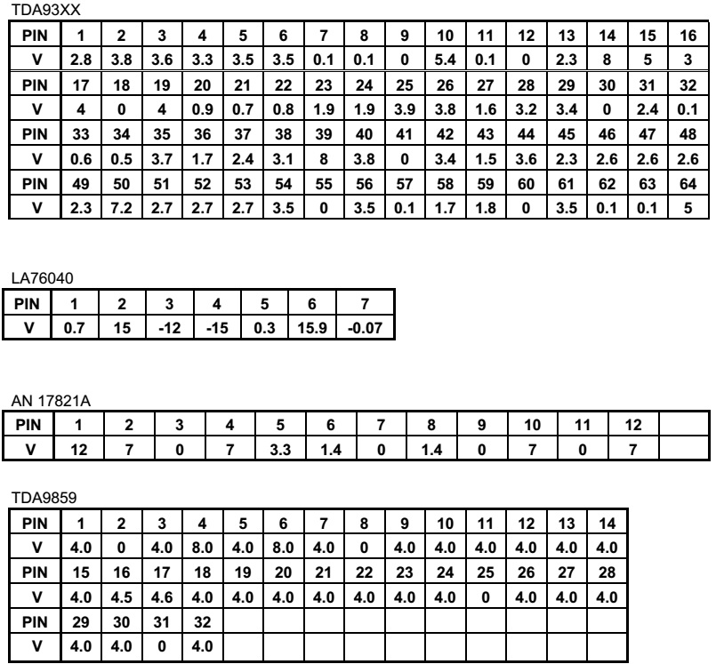
IC pin voltages
Full circuit diagram / Schematic and PWB
Click on the pictures to magnify