REPAIRING AND NOT THROWING AWAY

Richtige Fernseher haben Röhren!

Richtige Fernseher haben Röhren!

In Brief: On this site you will find pictures and technical information about Service Modes, Circuit Diagrams, Firmware Update procedure, Disassemble procedure, Universal remote control set-up codes, Troubleshooting and more....

If you go into the profession, you will obtain or have access to a variety of tech tips databases HERE IT IS Master Electronics Repair !.

These are an excellent investment where the saying: 'time-is-money' rules. However, to learn, you need to develop a general troubleshooting approach - a logical, methodical, method of narrowing down the problem. A tech tip database might suggest: 'Replace C536' for a particular symptom. This is good advice for a specific problem on one model. However, what you really want to understand is why C536 was the cause and how to pinpoint the culprit in general even if you don't have a service manual or schematic and your tech tip database doesn't have an entry for your sick TV or VCR.

While schematics are nice, you won't always have them or be able to justify the purchase for a one-of repair. Therefore, in many cases, some reverse engineering will be necessary. The time will be well spent since even if you don't see another instance of the same model in your entire lifetime, you will have learned something in the process that can be applied to other equipment problems.
As always, when you get stuck, checking out a tech-tips database may quickly identify your problem and solution.In that case, you can greatly simplify your troubleshooting or at least confirm a diagnosis before ordering parts.

Happy repairing!
Today, the West is headed for the abyss. For the ultimate fate of our disposable society is for that society itself to be disposed of. And this will happen sooner, rather than later.

How to use the site:

- If you landed here via any Search Engine, you will get what you searched for and you can search more using the search this blog feature provided by Google. You can visit more posts scrolling the left blog archive of all posts of the month/year,
or you can click on the main photo-page to start from the main page. Doing so it starts from the most recent post to the older post simple clicking on the Older Post button on the bottom of each page after reading , post after post.

You can even visit all posts, time to time, when reaching the bottom end of each page and click on the Older Post button.

- If you arrived here at the main page via bookmark you can visit all the site scrolling the left blog archive of all posts of the month/year pointing were you want , or more simple You can even visit all blog posts, from newer to older, clicking at the end of each bottom page on the Older Post button.
So you can see all the blog/site content surfing all pages in it.

- The search this blog feature provided by Google is a real search engine. If you're pointing particular things it will search IT for you; or you can place a brand name in the search query at your choice and visit all results page by page. It's useful since the content of the site is very large.

Note that if you don't find what you searched for, try it after a period of time; the site is a never ending job !

..............The bitterness of poor quality is remembered long after the sweetness of todays funny gadgets low price has faded from memory........ . . . . . .....
Don't forget the past, the end of the world is upon us! Pretty soon it will all turn to dust!

©2010, 2011, 2012, 2013, 2014 Frank Sharp - You do not have permission to copy photos and words from this blog, and any content may be never used it for auctions or commercial purposes, however feel free to post anything you see here with a courtesy link back, btw a link to the original post here , is mandatory.
All posts are presented here for informative, historical and educative purposes as applicable within fair use. NOTHING HERE IS FOR SALE !

Showing posts with label SANSUI. Show all posts

Saturday, 6 April 2019

SANSUI SV2918 CIRCUIT DIAGRAM

Sansui SV2918 Circuit diagram

Used ICs: STR-F6656 – TCLM13 – TB1240 – 4052 – TA1216AN – TDA2616Q – TA8427K – TA1275A – TDA9181
SV2518 – 64CM
SV2916i – nicam/secam
SV2918 – nicam
SV3418 – 87 cm
PAL BG, I, DK, NTSC 4.43 – NTSC 3.58(AV)
Circuit diagram

Click on the schematics to zoom in

Wednesday, 3 April 2019

SANSUI HDLCD 1909 - HOW TO ENTER SERVICE MODE - LCD TV

SANSUI HDLCD 1909 - HOW TO ENTER SERVICE MODE - LCD TV


CONFIRMATION OF INITIAL DATA {When replacing memory IC}
1. Turn on the POWER, and set to the ALL mode. ,
2. Set the VOLUME to minimum.
3. Press both VOL. DOWN button on the set and Channel button (8) on the remote control for more than 2 seconds.
4. After the confirmation of each check sum, turn off the power.
CONFIRMATION OF INITIAL DATA
CONFIRMATION OF CHECK SUM, POWER ON TOTAL HOURS AND MICON VERSION
Initial total of MEMORY IC, POWER ON total hours and MICON VERSION can be checked on the screen. Total hours are displayed in 16 system of notation.  NOTE: If you set a factory initialization, the total hours is reset to "0".
If a service repair is undertaken where it has been required to change the MEMORY IC, the following steps should be taken to ensure correct data settings while making reference to INITIAL SETTING TABLE (Attached "INITIAL DATA").
1. Turn on the POWER, and set to the ALL mode.
2. Set the VOLUME to minimum.
3. Press both VOL. DOWN button on the set and Channel button (6)on the remote control for more than 2 seconds. 3. Press both VOL. DOWN button on the set and Channel button (6)on the remote control for more than 2 seconds.
ADDRESS and DATA should appear as FIG.  NOTE: No need to set data other position than 0D00~0EFF.
4. ADDRESS is now selected and should "blink". Using the CH. UP/DOWN button on the remote, step through the ADDRESS
until required ADDRESS to be changed is reached.
5. Press VOL. UP/DOWN button to select DATA. When DATA is selected, it will "blink".
6 Again step through the DATA using CH UP/DOWN button until required DATA value has been selected
7. Pressing VOL. UP/DOWN button will take you back to ADDRESS for further selection if necessary.
8. Repeat steps 4 to 6 until all data has been checked.
9. When satisfied correct DATA has been entered, turn POWER off (return to STANDBY MODE) to finish DATA input.  After the data input, set to the initializing of shipping.
10. Turn on the Power.
11. Set the VOLUME to minimum.
12. Press both VOL. DOWN button on the set and Channel button (1)on the remote control for more than 2 seconds.
13. After the finishing of the initializing of shipping, the unit will turn off automatically.  The unit will now have the correct DATA for the new MEMORY IC.
SERVICE MODE
To enter to the SERVICE MODE function, press and hold both buttons simultaneously on the main unit and on the remote control for more than a the standard time in the appropriate condition.

Friday, 29 March 2019

FLYBACK EHT TRAFO - WINDING DATA HITACHI SANSUI TOSHIBA SOLIDTRON SHARP SAMSUNG AND GOLD STAR CTVS

LOT WINDING DATA Hitachi Sansui Toshiba Solidtron Sharp Samsung and Gold Star CTVs


Flyback Transformer winding Data - Hitachi _  Sansui _  Toshiba _  Solidtron _  Sharp _  Samsung _ Gold Star & Panasonic CTVs
Flyback TLF15644F1 Panasonic
TLF4N052 TLF4G503F
Flyback 154-177B Goldstar
154-064P FCK-14B047 JF0501-1206 JF0501-91802 154- 374A 6174Z-6238L
Flyback FOK14A001 Samsung
AA26-002101A FSV-14A004C
Flyback F0193PEN1-SA Sharp
F0194PEN1-SA F0147PE-M BCS21-2647 F0101KMSA F0102KM F02299PE-B F0141PE-M
Flyback FSV20A099 Sanken
Flyback 2435521 Hitachi
Flyback TFB4122BD Toshiba
TFB4125CH
Flyback DCF-2077D Solidtron
DCF-2077A DCF-1577 FSA16012M
Flyback JF0501-1206 Sansui
154-177B 154-064P FCK-14B047 JF0501-91802 154-374A 6174Z- 6238L
CLICK ON THE PICTURES TO ZOOM IN

Wednesday, 27 March 2019

SANSUI SV 21276 _ SERVICE MODE

SANSUI SV 21276 _ SERVICE MODE


TO ENTER FACTORY MODE [SERVICE MODE]

  • Reduce the Volume to Zero.
  • Simultaneoulsly press "Volume Dn" button at the Front panel of the TV set, and "Display" button on the remote control.  Service mode window will be displayed.
  • To exit service mode, press "Standby" button on the remote control.  Changed data settings will be stored automatically.

Thursday, 28 February 2019

SANSUI SVX – 2106R COLOR TV - USING STR S6708 - SWITCHING REGULATOR

SANSUI SVX – 2106R COLOR TV - USING STR S6708 - Switching Regulator

STR S6708 SMPS Power supply faults
 
       Power supply of this set is composed of STR S6708, and its regulation is controlled by the optocoupler TLP621GR F2.  The most common fault to the power supply section to this set is, blown out STR Switching regulator.  Before replacing the STR S6708, check first the two ceramic capacitors soldered to its pin number [1], C860-470PF & C862-IK8PF IKV.  Check the soldering to this C862 and check this capacitor for open. If this capacitor has some defect with it, the STR replaced will blow out as soon as the set is power ON.  Check L861 too for open circuit.
     We can check the STR S6708 for defect, with a multimeter.  The IC itself has internal control circuit, and one power transistor integrated.  Normally, the collector to emitter junction of this internal power transistor will get shorted, and a defective STR.  Pin number [3] of the STR is the base to internal switching transistor. Pin number [1] is its collector out, and pin number [2] is its emitter.
      Check these pins like we check an NPN transistor with a multimeter. Check whether there is shorted collector to emitter junction.  Just check the resistance between pint number [2] & [1].  In no case, this junction should show any conductance. If it show conductance, the STR is faulty and should be replaced.
Along with the STR, it is advised to replace the opto-coupler [IC 862 – TLP 621GR F2] too. Check the transistor [Q872 C3852] and two Zener diodes connected in series to its base connection [D872 and D871][both of them are 6.8V Zener diodes] These diodes along with the transistor [Q872] determines the input supply voltage to optocoupler, and should be very constant, otherwise conduction to the internal photo transistor of the optocoupler will differ, which in turn result a non-constant secondary power output [115VDC] from the secondary of the SMPS transformer, which in turn feeds the horizontal output section of the TV.
     The control voltage to the internal LED of the optocoupler has been derived from the collector of [Q884 – 2SA1015], and the base of this transistor is controlled by the voltage from the error amplifier [Q883 –SE117].  This error regulator senses the output voltage of the SMPS, and if any difference comes with 115VDC output, will be controlled.
     So when repair the power supply of this set for blown out STR S6707, all the above stated components must be checked.  If any one among them is defective, replaced STR will blow out.

Wednesday, 27 February 2019

HOW TO ENTER SERVICE MODE TO VIDEOCON/SANSUI TVs

HOW TO ENTER SERVICE MODE TO VIDEOCON/SANSUI TVs


  • To enter into service mode to these sets, press the service key [S].
  • If you press numerical key 1, the set will put into service mode.
  • Pressing digit key 2, the set will be put into Design mode.
  • Pressing digit key 3, will put the set into factory reset.
  • Pressing digit key 4, will put the set into Manufacturing mode.
  • To select an item to adjust, use [CH Up / CH Dn] keys on the remote control.
  • To adjust the data value of the selected item, use [Vol+ / Vol--ve] keys.
  • Press service key [S] again, to quit service mode

HOW TO ENTER SERVICE MODE TO SANSUI / SALORA / THOMSON / CALCOM / FUTEC / PHILIPS WITH 250 CHANNELS / V.SONI AND MICRO TVS [ ONE CHIP MICOM UOC KIT, USING TDA 9370 IC

HOW TO ENTER SERVICE MODE TO SANSUI / SALORA / THOMSON / CALCOM / FUTEC / PHILIPS WITH 250 CHANNELS / V.SONI AND MICRO TVS [ ONE CHIP MICOM UOC KIT, USING TDA 9370 IC


  • Entering into service mode to these sets, press [ PIC => 2 => 0 => 0 => 3]; on the remote control.  The remote control handset must be original.
  • To call an item to adjust, use [Ch Up / Ch Dn] keys.
  • To adjust the data value to selected item, press [Vol Up / Vol Dn] keys.
  • Press digit "8" on the remote control after service mode has been set, to adjust the white balance adjustment. [RGB], adjust.


  • Child lock passcode to these sets is [1227]

Wednesday, 20 February 2019

SANSUI & VIDEOCON - SV-1412 SV-2012 SERVICE MODE

SANSUI & VIDEOCON - SV-1412 SV-2012 SERVICE MODE


TO ENTER SERVICE MODE

  1. Short contact the 'Hidden' key inside the remote handset. "TEST" will be appear on the screen.
  2. Press numeric keys {1->2->3->5->6->7->8->9->0} by the remote control to select various adjustment modes on screen.
  3. Menu [3,4&5] are general menus.
  4. Menu [1,2,6,7,8,9,0] are special menus.  
  5. To access these menus, enter (9->9->1->2->2->0); when the 'TEST' appears on the screen.
  6. To call an item to adjust, use 'Up | Dn' keys on the remote control.
  7. To adjust the data value to selected item, use 'Volume Up | Volume Dn' keys on the remote control.
  8. To "Exit" service mode, again short circuit the hidden key inside the remote control

Wednesday, 13 February 2019

SANSUI -441_AM/FM STEREO RECEIVER_SCHEMATIC DIAGRAM

SANSUI -441_AM/FM STEREO RECEIVER_SCHEMATIC DIAGRAM


SANSUI 441
[1]


[2]


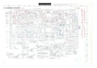
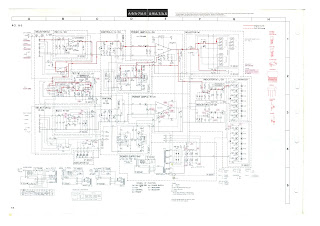
SANSUI - A-9 _ A-7 _ A-5 _ MASTER INTEGRATED AMPLIFIER _ SCHEMATIC DIAGRAM

SANSUI - A-9 _ A-7 _ A-5 _ MASTER INTEGRATED AMPLIFIER _ SCHEMATIC DIAGRAM


SANSUI  A-9 | A-7 | A-5 _ SCHEMATIC
[1]


[2]


[3]


Friday, 8 February 2019

SANSUI SVX – 2106R COLOR TV - USING STR S6708 - SWITCHING REGULATOR

SANSUI SVX – 2106R COLOR TV - USING STR S6708 - Switching Regulator

STR S6708 SMPS Power supply faults
       Power supply of this set is composed of STR S6708, and its regulation is controlled by the optocoupler TLP621GR F2.  The most common fault to the power supply section to this set is, blown out STR Switching regulator.  Before replacing the STR S6708, check first the two ceramic capacitors soldered to its pin number [1], C860-470PF & C862-IK8PF IKV.  Check the soldering to this C862 and check this capacitor for open. If this capacitor has some defect with it, the STR replaced will blow out as soon as the set is power ON.  Check L861 too for open circuit.
     We can check the STR S6708 for defect, with a multimeter.  The IC itself has internal control circuit, and one power transistor integrated.  Normally, the collector to emitter junction of this internal power transistor will get shorted, and a defective STR.  Pin number [3] of the STR is the base to internal switching transistor. Pin number [1] is its collector out, and pin number [2] is its emitter.
      Check these pins like we check an NPN transistor with a multimeter. Check whether there is shorted collector to emitter junction.  Just check the resistance between pint number [2] & [1].  In no case, this junction should show any conductance. If it show conductance, the STR is faulty and should be replaced.
Along with the STR, it is advised to replace the opto-coupler [IC 862 – TLP 621GR F2] too. Check the transistor [Q872 C3852] and two Zener diodes connected in series to its base connection [D872 and D871][both of them are 6.8V Zener diodes] These diodes along with the transistor [Q872] determines the input supply voltage to optocoupler, and should be very constant, otherwise conduction to the internal photo transistor of the optocoupler will differ, which in turn result a non-constant secondary power output [115VDC] from the secondary of the SMPS transformer, which in turn feeds the horizontal output section of the TV.
     The control voltage to the internal LED of the optocoupler has been derived from the collector of [Q884 – 2SA1015], and the base of this transistor is controlled by the voltage from the error amplifier [Q883 –SE117].  This error regulator senses the output voltage of the SMPS, and if any difference comes with 115VDC output, will be controlled.
     So when repair the power supply of this set for blown out STR S6707, all the above stated components must be checked.  If any one among them is defective, replaced STR will blow out.