REPAIRING AND NOT THROWING AWAY

Richtige Fernseher haben Röhren!

Richtige Fernseher haben Röhren!

In Brief: On this site you will find pictures and technical information about Service Modes, Circuit Diagrams, Firmware Update procedure, Disassemble procedure, Universal remote control set-up codes, Troubleshooting and more....

If you go into the profession, you will obtain or have access to a variety of tech tips databases HERE IT IS Master Electronics Repair !.

These are an excellent investment where the saying: 'time-is-money' rules. However, to learn, you need to develop a general troubleshooting approach - a logical, methodical, method of narrowing down the problem. A tech tip database might suggest: 'Replace C536' for a particular symptom. This is good advice for a specific problem on one model. However, what you really want to understand is why C536 was the cause and how to pinpoint the culprit in general even if you don't have a service manual or schematic and your tech tip database doesn't have an entry for your sick TV or VCR.

While schematics are nice, you won't always have them or be able to justify the purchase for a one-of repair. Therefore, in many cases, some reverse engineering will be necessary. The time will be well spent since even if you don't see another instance of the same model in your entire lifetime, you will have learned something in the process that can be applied to other equipment problems.
As always, when you get stuck, checking out a tech-tips database may quickly identify your problem and solution.In that case, you can greatly simplify your troubleshooting or at least confirm a diagnosis before ordering parts.

Happy repairing!
Today, the West is headed for the abyss. For the ultimate fate of our disposable society is for that society itself to be disposed of. And this will happen sooner, rather than later.

How to use the site:

- If you landed here via any Search Engine, you will get what you searched for and you can search more using the search this blog feature provided by Google. You can visit more posts scrolling the left blog archive of all posts of the month/year,
or you can click on the main photo-page to start from the main page. Doing so it starts from the most recent post to the older post simple clicking on the Older Post button on the bottom of each page after reading , post after post.

You can even visit all posts, time to time, when reaching the bottom end of each page and click on the Older Post button.

- If you arrived here at the main page via bookmark you can visit all the site scrolling the left blog archive of all posts of the month/year pointing were you want , or more simple You can even visit all blog posts, from newer to older, clicking at the end of each bottom page on the Older Post button.
So you can see all the blog/site content surfing all pages in it.

- The search this blog feature provided by Google is a real search engine. If you're pointing particular things it will search IT for you; or you can place a brand name in the search query at your choice and visit all results page by page. It's useful since the content of the site is very large.

Note that if you don't find what you searched for, try it after a period of time; the site is a never ending job !

..............The bitterness of poor quality is remembered long after the sweetness of todays funny gadgets low price has faded from memory........ . . . . . .....
Don't forget the past, the end of the world is upon us! Pretty soon it will all turn to dust!

©2010, 2011, 2012, 2013, 2014 Frank Sharp - You do not have permission to copy photos and words from this blog, and any content may be never used it for auctions or commercial purposes, however feel free to post anything you see here with a courtesy link back, btw a link to the original post here , is mandatory.
All posts are presented here for informative, historical and educative purposes as applicable within fair use. NOTHING HERE IS FOR SALE !

Showing posts with label SERVICE MODE. Show all posts

Friday, 16 October 2020

PHILIPS 40PFT6709 - CHASSIS TPM14.2A SERVICE MODE, OPTIONS SETTINGS, SERVICE ALIGNMENTS, DIAGNOSING ERROR CODES, LED BLINKING CODES AND MORE OTHER

TPM14.2A Chassis


Always respect voltages. While some may not be dangerous in themselves, they can cause unexpected reactions that are best avoided. Before reaching into a powered TV set, it is best to test the high voltage insulation.
It is easy to do, and is a good service precaution.

The TPM14.2A LA is a new chassis launched in Asia in 2014.
The whole range is covered by SCALER MT5591.
The major deltas versus its predecessor DVB-TC; DVB-TC/T2,
with also multi-media, 3D, Ambilight, WIFI, Smart TV, Light Sensor functionality.
The TPM14.2A LA chassis comes with the following styling:
• series xxPFT6700
• series xxPFT6900
• series xxPUT8500
• series xxPUT8600

Key components of this chassis are:
• SCALER MT5591IVDJ HSBGA-758 TV Processor
• TUNER EUROPE SUT-RE231ZN (DVB-T/C, T2 analogue)
• DEMODULATOR CXD2837ER-T4 VQFN-48
• STA381BWTR 20W VQFN-48 for AUDIO Amplifier
• THGBM5G5A1JBAIR 4GB P-VFBGA153 for EMMC IC


It should be noted that on the European Service website, “Alternative BOM” is referred to as “Design variant”.
The third digit in the serial number (example: AG2B0335000001) indicates the number of the alternative B.O.M. (Bill Of Materials) that has been used for producing the specific TV set. In general, it is possible that the same TV model on the market is produced with e.g. two different types of displays, coming from two different suppliers. This will then result in sets which have the same CTN (Commercial Type Number; e.g. 28PW9515/12) but which have a different B.O.M. number.
By looking at the third digit of the serial number, one can identify which B.O.M. is used for the TV set he is working with.
If the third digit of the serial number contains the number “1” (example: AG1B033500001), then the TV set has been manufactured according to B.O.M. number 1. If the third digit is a “2” (example: AG2B0335000001), then the set has been produced according to B.O.M. no. 2. This is important for ordering the correct spare parts.
For the third digit, the numbers 1...9 and the characters A...Z can be used, so in total: 9 plus 26= 35 different B.O.M.s can be indicated by the third digit of the serial number.

Identification: The bottom line of a type plate gives a 14-digit serial number. Digits 1 and 2 refer to the production centre (e.g. SN is Lysomice, RJ is Kobierzyce), digit 3 refers to the B.O.M. code, digit 4 refers to the Service version change code, digits 5 and 6 refer to the production year, and digits 7 and 8 refer to production week (in example below it is 2010 week 10 / 2010 week 17). The 6 last digits contain the serial number. 

Board Level Repair (BLR) or Component Level Repair (CLR)
If a board is defective, consult your repair procedure to decide if the board has to be exchanged or if it should be repaired on component level.
If your repair procedure says the board should be exchanged completely, do not solder on the defective board. Otherwise, it cannot be returned to the O.E.M. supplier for back charging


Service Mode.  Service Alignment Mode (SAM)

How to Activate SAM
To activate SAM, use one of the following methods:
• Press the following key sequence on the remote control transmitter: “062596”, directly followed by the “INFO/OK” button. Do not allow the display to time out between entries while keying the sequence.
• Or via ComPair.
After entering SAM, the following items are displayed, with “SAM” in the upper right corner of the screen to indicate that the television is in Service Alignment Mode.

Software Identification, Version, and Cluster
The software ID, version, and cluster will be shown in the main menu display of SAM and CSM.
The screen will show: “AAAAB-X.YYY”, where:
• AAAA is the chassis name: QN142A x.yy.
• B is the region indication: E = Europe, A = AP/China, U = NAFTA, L = LATAM.
• X is the main version number: this is updated with a major change of specification (incompatible with the previous software version). Numbering will go from 1 - 99 and AA - ZZ.
- If the main version number changes, the new version number is written in the NVM.
- If the main version number changes, the default settings are loaded.
• YYY is the sub version number: this is updated with a minor change (backwards compatible with the previous versions). Numbering will go from 000 - 999.
- If the sub version number changes, the new version number is written in the NVM.
- If the NVM is refreshed, the software identification, version, and cluster will also be written to NVM.

Display Option Code Selection
When after an SSB or display exchange, the display option code is not set properly, it will result in a TV with “no display”.
Therefore, it is required to set this display option code after such a repair.
To do so, press the following key sequence on a standard RC transmitter: “
062598” directly followed by MENU and “xxx”, where “xxx” is a 3 digit decimal value of the panel type.  When the value is accepted and stored in NVM, the set will switch to Stand-by,
to indicate that the process has been completed.
During this algorithm, the NVM-content must be filtered, because several items in the NVM are TV-related and not SSB related (e.g. Model and Prod. S/N). Therefore, “Model” and “Prod. S/N” data is changed into “See Type Plate”. In case a call centre or consumer reads in CSM mode.

How to Navigate
• In the SAM menu, select menu items with the UP/DOWN keys on the remote control transmitter. The selected item will be indicated. When not all menu items fit on the screen, use the UP/DOWN keys to display the next/previous menu items.
• With the “LEFT/RIGHT” keys, it is possible to:
– (De) activate the selected menu item.
– (De) activate the selected sub menu.
– Change the value of the selected menu item.
• When you press the MENU button once while in top level SAM, the set will switch to the normal user menu (with the SAM mode still active in the background).
• Press the following key sequence on the remote control transmitter: “
062596” directly followed by the “Home/Menu” button to switch to SDM (do not allow the display to time out between entries while keying the sequence).
How to Store SAM Settings
To store the settings changed in SAM mode (except the RGB Align settings), leave the top level SAM menu by using the POWER button on the remote control transmitter or the television set. The mentioned exceptions must be stored separately via the STORE button.
How to Exit SAM
Use one of the following methods:
• Switch the set to STANDBY by pressing the mains button on the remote control transmitter or the television set.
• Via a standard RC-transmitter, key in “00” sequence.
Note: When the TV is switched “off” by a power interrupt while in SAM, the TV will show up in “normal operation mode” as soon as the power is supplied again. The error buffer will not be cleared.

How to Activate the Factory mode
To activate the Factory mode, use the following method:
• Press the following key sequence on the remote control transmitter: from the “
menu/home” press “1999”, directly followed by the “Back/Return” button. Do not allow the display to time out between entries while keying the sequence.
After entering the Factory mode, the following items are displayed,

How to Exit the Factory mode
Use one of the following methods:
• Select
EXIT-FACTORY from the menu and press the “OK” button.
Note: When the TV is switched “off” by a power interrupt, or normal switch to “stand-by” while in the factory mode, the TV will show up in “normal operation mode” as soon as the power is supplied again. The error buffer will not be cleared.

SAM mode and Factory mode overview


How to Copy NVM Data to/from USB

When copying data to and from a USB memory stick, the folder “repair” is used. When inserting an empty USB memory stick, and downloading data to the stick, the TV will create this folder.
When sending data from a USB memory stick to a TV, the intended data must be available in the “repair” folder.
Note that when copying EDID data to the TV, all necessary EDID files must be in this folder.
Service mode overview for your reference.

Error Codes
Error codes are required to indicate failures in the TV set. In principle a unique error code is available for every:
• Activated (SW) protection.
• Failing I2C device.
• General I2C error.
The last five errors, stored in the NVM, are shown in the Service menu’s. This is called the error buffer.  The error code buffer contains all errors detected since the last  time the buffer was erased. The buffer is written from left to  right. When an error occurs that is not yet in the error code buffer, it is displayed at the left side and all other errors shift one position to the right.
An error will be added to the buffer if this error differs from any error in the buffer. The last found error is displayed on the left.
An error with a designated error code never leads to a deadlock situation. It must always be diagnosable (e.g. error buffer via OSD or blinking LED or via ComPair).
In case a failure identified by an error code automatically results in other error codes (cause and effect), only the error code of the MAIN failure is displayed.

How to Read the Error Buffer
You can read the error buffer in three ways:
• On screen via the SAM/CSM (if you have a picture).
Example:
ERROR: 000 000 000 000 000: No errors detected
ERROR: 013 000 000 000 000: Error code 13 is the last and only detected error
ERROR: 034 013 000 000 000: Error code 13 was detected first and error code 34 is the last detected (newest) error

• Via the blinking LED procedure (when you have no picture).

Error codes
In this chassis only “layer 2” error codes are available and point to problems on the SSB. They are triggered by LED blinking when CSM is activated. Only the following layer 2 errors are defined:

How to Clear the Error Buffer
The error code buffer is cleared in the following cases:
• By using the CLEAR command in the SAM menu
• By using the CLEAR command in the Factory mode:
• By using the following key sequence on the remote control transmitter: “
062599” directly followed by the OK button.
• If the contents of the error buffer have not changed for 50 hours, the error buffer resets automatically.
Note: If you exit SAM by disconnecting the mains from the television set, the error buffer is not reset.

The Blinking LED Procedure
The software is capable of identifying different kinds of errors.
Because it is possible that more than one error can occur over time, an error buffer is available, which is capable of storing the last five errors that occurred. This is useful if the OSD is not working properly.
Errors can also be displayed by the blinking LED procedure.
The method is to repeatedly let the front LED pulse with as many pulses as the error code number, followed by a period of 1.5 seconds in which the LED is “off”. Then this sequence is repeated.
Example (1): error code 4 will result in four times the sequence LED “on” for 0.25 seconds / LED “off” for 0.25 seconds. After this sequence, the LED will be “off” for 1.5 seconds. Any RC command terminates the sequence. Error code LED blinking is in red color.
Example (2): the content of the error buffer is “
12 9 6 0 0” After entering SDM, the following occurs.
• 1 long blink of 5 seconds to start the sequence.
• 12 short blinks followed by a pause of 1.5 seconds.
• 9 short blinks followed by a pause of 1.5 seconds.
• 6 short blinks followed by a pause of 1.5 seconds.
• 1 long blink of 1.5 seconds to finish the sequence.
• The sequence starts again with 12 short blinks.

RGB Alignment
Before alignment, set the picture as follows:


White Tone Alignment:
• Activate SAM.
• Select “RGB Align.” and choose a color temperature.
• Use a 100% white screen as input signal and set the following values:
– “Red BL Offset” and “Green BL Offset” to “7” (if present).
– All “White point” values initial to “128”.

In case you have a colour analyser:
• Measure with a calibrated (phosphor- independent) color analyser (e.g. Minolta CA-210) in the centre of the screen.
Consequently, the measurement needs to be done in a dark environment.
• Adjust the correct x, y coordinates (while holding one of the White point registers R, G or B on max. value) by means of decreasing the value of one or two other white points to the correct x, y coordinates (see Table below) tolerance: dx: ± 0.003, dy: ± 0.003.
• Repeat this step for the other colour Temperatures that need to be aligned.
• When finished return to the SAM root menu and press STANDBY on the RC to store the aligned values to the NVM.  If you do not have a colour analyser, you can use the default values. This is the next best solution. The default values are average values coming from production (statistics).


Display Adjustment
You can use the default values. The default values are average values coming from production.
• Enter SAM mode.
• Select a colour temperature (e.g. COOL, NORMAL, or WARM).
• Set the RED, GREEN and BLUE default values according to the values.
• When finished press OK on the RC, then press STORE to store the aligned values to the NVM.
• Restore the initial picture settings after the alignments


Option Settings
The microprocessor communicates with a large number of I2C ICs in the set. To ensure good communication and to make digital diagnosis possible, the microprocessor has to know which ICs to address. The presence / absence of these NT72567 ICs is made known by the option codes.
Notes:
• After changing the option(s), save them by pressing the OK button on the RC before the cursor is moved to the left, select STORE and press OK on the RC.
• The new option setting is only active after the TV is switched “off” / “stand-by” and “on” again with the mains switch (the NVM is then read again).

Reset of Repaired SSB
A very important issue towards a repaired SSB from a Service repair shop (SSB repair on component level) implies the reset of the NVM on the SSB.
A repaired SSB in Service should get the service Set type “00PF0000000000” and Production code “00000000000000”.
Also the virgin bit is to be set. To set all this, you can use the ComPair tool or use the “NVM editor” and “Dealer options” items in SAM (do not forget to “store”).
After a repaired SSB has been mounted in the set (set repair on board level), the type number (CTN) and production code of the TV has to be set according to the type plate of the set. For this, you can use the NVM editor in SAM. The loading of the CTN and production code can also be done via ComPair
(Model number programming).
In case of a display replacement, reset the “Operation hours display” to “0”, or to the operation hours of the replacement display.
Remark:
- After the NVM has been replaced, go to SAM and scroll to the <Reload MAC address>
- Select the item and press <OK> on the RC.

Reset of Repaired SSB
After NVM replacement, reload MAC address via SAM menu. This ensures the correct MAC address to be available in CSM for future repair actions.
Way of working:
• After the NVM has been replaced, go to SAM and scroll to the <Reload MAC address> .
• Select the item and press <OK> on the RC.
Notes:
• Only applicable to all related models that are “Smart TV level 0”enabled (only YouTube access). For models without internet connection feature, no action is needed.
• HDCP keys are located in the NVM. If you are loading NVM with the ComPair tool, there is warning message displayed.
New NVM EEPROMs are shipped with pre-loaded HDCP keys.
SSB Identification
SSB’s of this chassis are identified by a “715” code on the SSB.
715Axxxx-Nnn-MMM-OOOO
715 main category, Printed Wiring Board
Axxxx sub category, sequential coding number
Nnn Version code
N Development number
nn Production number
MMM Mounting variation code
OOOO Optional variation code
Make sure when replacing an SSB the SSB identification codes match the replacement panel.


Thursday, 15 October 2020

SERVICING PHILIPS LCD LED TV ENTERING SERVICE MODE


PHILIPS SERVICE MODE
22PFL 4407\V7 LCD MENU+2580
22PFL5557/V7 LED MENU+2580
24PFL5557\V7 LED MENU+2580
24PFL5957\V7 LED MENU+2580
32PFL4537\V7 LED MENU+2580
32PFL4737/V7 LED MENU+2580
32PFL5537\V7 LED MENU+2580
32PFL5937\V7 LED MENU+2580
22PFL5237\V7 LED MENU+2580
24PFL3457\V7 LCD MENU+1950
24PFL5007\V7 LED MENU+1950
24PFL5237/V7 LED MENU+1950
24PFL5637/V7 LCD MENU+195LL0
24PFL5957\V7 LCD MEMU+1950
32PFL3057\V7 LCD MENU+1950
32PLF5007/V7 LED MEMU+1950
32PFL5237\V7 LED MENU+1950
32PFL5537\V7 LCD MENU+1950
32PFL5637\V7 LCD MENU+2580
32PFL6357\V7 LED MENU+1950
32PFL6577\V7 LCD MENU+1950
32PFL7977\V7 LED MENU+1950
42PFL3457\V7 LED MENU+1950
42PFL6357V7 LED MENU+1590
42PFL6577\V7 LED MENU+1950
42PFL7357\V7 LED MENU+1950
42PFL7977\V7 LED MENU+1950
46PFL8577\V7 LED MENU+1950
58PFL9577\V7 LED MENU+1950
40PFL4757\V7 LED MENU+2580
42PFL6977\V7 LED MENU+1950
MODEL NAME (TOP)
SERVICE MODE(DOWN)
24PFL4555
MENU+SOUND+8532
14PT3525
MENU-PICTURE-CONTRAST-9735
14PT4525
MENU-PICTURE-CONTRAST-9735
21PT3525
MENU-PICTURE-CONTRAST-9735
21PT4525
MENU-PICTURE-CONTRAST-9735
21PT5525
MENU-1147
24PFL4505
MENU+CONT+1950
24PFL5505
MENU+CONT+1950
24PFL5555
MENU+CONT+1950
32PFL3305
MENU+CONT+1950
32PFL4305
MENU+CONT+1950
32PFL4355
MENU+SOUND+8532
32PFL5355
MENU+CONT+1950
32PFL5505
MENU+CONT+1950
42PFL3505
MENU+CONT+1950
42PFL4755
MENU+SOUND+8532
42PFL5505
MENU+CONT+1950
42PFL5555
MENU+CONT+1950
46PFL5505
MENU+CONT+1950
46PFL5755
MENU+CONT+1950
46PFL6755
MENU+2008
55PFL5755
MENU+CONT+1950
55PFL6755
MENU+2008
21PT3426
MENU + 1947
32PFL5356
MENU + 1999 + BACK SPACE
32PFL5556
MENU + 1999 + BACK SPACE
42PFL5556
MENU + 1999 + BACK SPACE
46PFL5556
MENU + 1999 + BACK SPACE
42PFL6556
MENU + 1999 + BACK SPACE
46PFL6556
MENU + 1999 + BACK SPACE
32PFL4356
MENU + 2580 + OK
32PFL4556
MENU + 2580 + OK
22PFL4506
MENU+2580
26PFL4306
MENU+2580
42PFL5506
MENU+1999+BACK
24PFL5306
MENU+1950
32PFL5306
MENU+1950
32PFL6306
MENU+1950
32PFL6506
MENU+1950
22PFL4556
MENU + 2580 + OK
21PT4326
MENU + 1147
14PT3626
MENU + PICTURE MENU + 6483
21PT3326
MENU + PICTURE MENU + 6483
14PT4626
MENU + PICTURE MENU + 6483
21PT4226
MENU + PICTURE MENU + 6483
21PT3626
MENU + PICTURE MENU + 6483
21PT4626
MENU + PICTURE MENU + 6483
14PT3426
MENU + 1947
24PFL6306
MENU+1950
32PFL5007
MENU+1950
24PFL5007
MENU+1950
32PFL3057
MENU + 1950
42PFL3457
MENU + 1950
22PFL4407
MENU+2580
24PFL5237
MENU+1950
24PFL5637
MENU+1950
32PFL5237
MENU+1950
32PFL6577
STANDBY-UP-DOWN_DOWN
42PFL6577
STANDBY-UP-DOWN_DOWN
32PFL5637
MENU + 1950
14PT2407
MENU+1147
21PT4327
MENU+1147
42PFL7357
MENU + 1950
24PFL3457
MENU + 1950
22PFL5237
MENU + 1950
21PT3427
MENU+1147
21PT3527
MENU+1147
22PFL5557
MENU+2580
24PFL5557
MENU+2580
21PT5527
MENU+1147
32PFL4737
MENU+2580
14PT2307
MENU+1147
32PFL6357
MENU+1950
32PFL5957
MENU+2580
24PFL5957
MENU+2580
32PFL5537
MENU+2580
32PFL5937
MENU+2580
42PFL6357
MENU+1950
42PFL7977
STANDBY-UP-DOWN_DOWN
32PFL7977
STANDBY-UP-DOWN_DOWN
21PT4627
MENU+1147
40PFL4757
MENU+2580
32PFL4537
MENU+2580
46PFL8577
STANDBY-UP-DOWN_DOWN
58PFL9577
STANDBY-UP-DOWN_DOWN
42PFL6977
STANDBY-UP-DOWN_DOWN
24PFL3538
MENU-2580
32PFL6977
STANDBY-UP-DOWN_DOWN
29PFL5937
MENU+2580
21PT3428
MENU+1147
21PT4628
MENU+1147
14PT2508
MENU+1147
22PFL5237
MENU + 1950
21PT4428
MENU+1147
21PT3326
MENU + PICTURE MENU + 6483
14PT4428
MENU+1147
21PT3527
MENU+1147
22PFL2658
MENU+1950
24PFL3938
MENU+1950
22PFL2658
MENU + 1950
20PFL3938
MENU+1950
22PFL3958
MENU+1950
32PFL3938
MENU+1950
24PFL5237
MENU + 1950
24PFL4738
MENU+1950
22PFL4758
MENU+1950
32PFL4938
MENU+1950
29PFL4938
MENU+1950
29PFL4738
MENU-2580
32PFL4738
MENU+1950
40PFL4758
MENU+1950
50PFL4758
MENU-2580
46PFL4758
MENU+1950
32PFL5578
STANDBY-UP-DOWN_DOWN
32PFL3738
MENU+1950
22PFL3758
MENU+1950
40PFL4958
MENU+1950
46PFL8777
STANDBY-UP-DOWN_DOWN
20PFL3738
MENU+1950
32HFL4738
MENU+1950
29PFL4738
MENU-2580
24PFL3159
MENU+1950
20PFL2139
MENU+1950
32PFL3439
MENU+1950
39PFL4579
STANDBY-UP-DOWN_DOWN
21PT3428
MENU+1147
40PFL5059
MENU-2580
22PFL3459
MENU+1950
32PFL5039
MENU-2580
21PT4428
MENU+1147
21PT5527
MENU+1147
39PFL3559
MENU+1950
32PFL4479
MENU-1950
24PFL2159
MENU+1950

Friday, 2 October 2020

TCL C48P1FS - TCL 48 INCH CURVED LED TV HOW TO ENTER THE SERVICE MODE, SERVICE ADJUSTMENTS, AUDIO OUTPUT AND POWER (SMPS) SCHEMATIC DIAGRAM


C48P1FS-MT56CT-AP – TCL 48 inch Curved LED TV – service mode – service adjustments – software upgrade – audio output and SMPS circuit diagram

MT56-AP chassis are designed for Asia & Pacific (AP) market Ready for Smart TV. It features by its high integration, easy debugging (ADC adjustment free) as well as convenience in terms of maintenance. Fast software upgrade through USB disk facilitates both manufacture and after-sale service.

Note: Factory Main Menu (FMM) is divided into Factory menu and Design menu. Factory Menu covers all indispensable functions during manufacture such as White Balance Adjustment, SHOP etc., while Design Menu includes Service Menu, Hotel Menu, Param
Setting, Other Setting etc. Some settings like Param Setting and Other Setting is exclusively used by R&D engineer, anyone else shouldn’t change the settings in the menu. When you wish to learn the product information like project ID, project name, Hardware, software version, release date, you can access to Service Menu. In addition, in Hotel Menu,  also provide a great deal of useful functions for specific applications in hotel.

The main chip is from REALTEK and supports below features matrix:

Factory Test & Alignment Specification For MT56-AP Series (V1.0)

The software boot for U702 can be programed by Flash Tool.exe.
Every set has its unique HDCP key which is purchased from suppliers or HDCP certification authority. Please check HDCP function in the process of production.
Once in a while, the software of main board may be upgraded. Please pay attention to use the latest software before production.

Factory Menu
Factory Menu is mainly used for factory production and satisfies various demands of customers. It covers all indispensable functions during manufacture such as Warm up, White Balance, Shop, NVM Reset, Power on mode, USB Clone etc.

Accessing Way
a. When the Factory hotkey item of Factory Menu is disabled (OFF), press Menu button of remote control, then select Settings/Picture, make sure the cursor stop on Contrast item submenu. Finally, press 9, 7, 3, 5 consecutively.
b. When the Factory hotkey item of Factory Menu is enabled (ON, you can see the flashing Factory Captions Info on the lower left corner), press Back button of remote control.
Press RCU “OK” key to enter the submenu.
Press RCU “Right” or “Left” key to change the values.
Press RCU “Right” or “Left” key run the function.
Press RCU “Back” or “Menu” key exit the Factory menu.
Factory Captions Info:
While “FactoryKey” is enabled, there is some toggled display information relative to MV, SV, ID, MID, to facilitate 100% quick screening without accessing to whatever else menu:

P (Production/Factory mode flag)
MV (Mboot SW Version)
SV (Main SW Version)
ID (Project ID)
MEMC

Factory menu

White Balance Menu
Press the button on remote control to select certain item and OK to adjust White Balance.

Design Menu includes Factory Menu, other, Service Menu, Param Setting, Hotel Menu.
Some settings like Param Setting and Other Menu is exclusively used by R&D engineer, anyone else shouldn’t change the settings in the menu. When you wish to learn the product information like project ID, project name, chassis name, software version, release date, you can access to Service Menu. In addition, in Hotel Menu, we also provide a great deal of useful functions for specific applications in hotel.

Accessing Way
a. When the Design mode hotkey item is disabled(OFF), press Menu button of remote control, then select Settings/ Picture, make sure the cursor stop on Contrast item submenu, press 1, 9, 5, 0 consecutively.
b. When the Design mode hotkey item of Design Menu is enabled (ON, you can see the flashing Factory Captions Info on the lower left corner), press Back button of remote control.
Press RCU OK key to enter the submenu.
Press RCU Right/Left key to change the values.
Press RCU Right/Left key run the function.
Press RCU Back/Menu key exit the Factory menu.
Design Captions Information is the same to Factory Captions Info.

Other Menu
The Other Menu contains some TV basic information, with which we can check the TV setting before production.

Service Menu
Service Menu contains some basic information of the device, such as Project ID, Hardware, Software version, USB Update etc. This menu is especially useful for after-sale service.

Param (Parameter) Setting Menu
Param Setting menu contains Sound Setting, Picture Curve, Picture Setting, SSC, DBC, CI Card, Over scan, WIFI CHECK and USB FILE. But it is exclusively used by R&D engineer, anyone else shouldn’t change the settings in the menu.

All tests and measurements mentioned hereafter have to be carried out at a normal mains voltage (100 ~ 240 VAC)

All voltages have to be measured with respect to ground, unless otherwise stated All final tests have to be done on a complete set including LCD panel in a room with temperature of 25+/-7°C

The Picture Performance assessment such as White Balance (luminance and colour temperature) has to be performed into subdued lighted room after at least 60min of warm-up in order to avoid any temperature drift influence (colorimetry vs time).

Pre-Conditions and Power Supply Check
Before power-on, please check the board according to the relevant block diagram and circuit diagram, make sure that no serious issue or mistake can destroy the board. For example, the output of DC/DC and LDO should not be shorted to ground.
Supply a suited voltage and power-on, then check the voltage according to the relevant block diagram, circuit diagram and voltage spec, the error should be less than 5%, for example, the voltage for main chip (+3V3, +2.5V, VDDC1V15, 1V5_DDR, etc.), the voltage for TUNER (TU_3V3), the voltage for amplifier (AMP_VCC), etc.

Project ID Modification
There are different ID stored in the EMMC depending on different Panels settings and Model features, but there’s only one key branching Project ID able to ensure normal display. And when you power on the TV set, you should make sure the Project ID is accord with the BOM description. If not, you need to modify the ID. There are two methods to modify the ID:

Change Project ID in Design Menu
In case of “Design mode hotkey” is enabled, press “Back” button to enter Design Menu. To modify Project ID, you need to go through “Service menuàProject ID”, then press Left or Right key to select suitable ID (Project name is dynamically refreshed). Finally restart the TV set.
In case of “Design mode hotkey” is unabled, you can enter the Design Menu easily with reference to 3.1 Design Menu.

Change Project ID with RCU
Press “062598”+”Menu”+”XXX” (XXX represents project ID you’d like to switch to) in the remote control and wait about half minutes, When the set restart automatically, you have successfully changed project ID.
Here below is none exhaustive ProjectID table for reference:

Function Test
Once the Project ID is correct and the TV display normally, plug all external generator devices to relevant inputs/outputs below according to their respective test patterns format and check picture content and sound quality accordingly:

LAN/WLAN Test: MAC Address Upgrade
Upgrading MAC address needs to use the tool in factory and through serial command. The specific method is according to the operation of the factory guidance.

DeviceID (DID) and UserID (UID)
Purpose is to allow Other Network Download (OND) and further specific services over dedicated portal based on AP. For such, specific DID (32 bytes) and UID (8 bytes) needs to be paired and overwritten into memory for internal client encryption, as below:

Those DID/UID codes can only be set using UART commands following enclosed SIACP requirements (rev. v3.9).

LAN Test
A rough LAN test can be done by connecting Ethernet to TV’s RJ45 and check that IP, subnet mask, DNS addresses, which are visible on “HomeàSettingsàNetworkàEthernet settingsàIP settings” (ensure that “Internet Connection” is Enabled at first). More in-depth test can be performed faster using suitable UART/IR commands following SIACP requirements. SW will internally manage Network ID (NID) flag controlling all MAC/DID/UID integrity to facilitate PA screening further.

SHOP INIT (Intilization)
At final process stage, it’s necessary to perform Shop init before any packing to leave Factory mode and restore User default presets according to the requirement of order.
This function is accessible by selecting “Factory Menu 
à Shop”, then pressing RCU “Right ”or” Left” key.  Other faster methods are available on above enclosed SIACP requirements (rev. v3.9).

Warm-up Test
Following TCL standard and practices, it’s required minimum 15min of Warm-Up that can be considered as Burn-In. Additional aging for White Balance alignment is no more necessary due to consistent picture performance with cloning usage. This function is accessible by selecting “Factory menu à Warm up”, pressing RCU “Right” or ”Left” key to set it ON, and then it enter in Warm up mode. Press “Menu” key on keyboard to exit the burning mode. Other faster methods are available on above enclosed SIACP requirements (rev. v3.9)

Software Upgrade: How to upgrade Mboot
Connect the computer and mainboard VGA port by a serial port tool. Serial connector definition: VGA/P303: Pin4: RXD VGA Pin11:TXD
Open MTK “Mboot” software programming tool “Flash Tool”, and set serial port.

Import the mboot file, as below

power on the TV, then Click Upgrade key and you will see the below message.

How to upgrade FLASH Software
USB Upgrade Download the update file (generally named V8-MT56551-LF1VXXX.pkg) to the root directory of your USB device, and make sure there’s no other bin file named analogously. Then insert the USB device to USB interface of TV set.
Power on the TV set, Press and hold on the menu key of key board at the same time. If the TV is updating, you’ll see the  screen:

Upgrade process takes about 3 to 5 minutes.
After updating, the TV set will reset automatically.

Online Upgrade
Download the bin zip file “V8-MT56551-LF1VXXX.Zip” to the root directory of your USB device, and do not change the file name. Then insert the USB device to USB interface of TV set.
Press RCU Menu/Settings/Picture/Contrast/1,9,5,0/Service menu/USB Update /Main Upgrade/Local Update . If the upgrade file is found, TV will give a message that it verifying. TV displays a warning message, it means selecting “confirm” to continue or “cancel” to exit. During updating, do not power off the TV set.
After updating, the TV set will reset automatically.

Network Connection
You can set up your TV so that it can access the Internet through your local area network (LAN) using a wired or wireless connection.
Connect to a wired network
Attach the TV set to your LAN using cable in three ways:
Connecting the LAN port on the TV to an external modem using a Cat 5 cable.
Connecting the LAN port on the TV to an IP Sharer which is connected to an external modem. Use Cat 5 cable for the connection.
Depending on how your network is configured, you may be able to attach the TV to your LAN by connecting the LAN port on your TV directly to a network wall outlet using a network cable. Note that the wall outlet is attached to a modem or router anywhere in your house.
Select Home → Settings → Network → Ethernet Settings →IP Settings, then the TV will obtain IP address Automatic configuration. In addition, you can set the IP address and password manually.

Connecting to a wireless network
To connect the TV set to your network wirelessly, you need a wireless router or modem and a Wireless LAN Adapter.
If the TV set is equiped with an internal WiFi module, select Home → Settings → Network → Wireless Settings, then turn on Wireless Switch, select a wireless network and press OK to connect.
If you want to connect the TV set to a wireless network by a Wireless High Gain USB Adapter (USB dongle), select Home → Settings → Network → Wireless Settings, then turn on Wireless Switch and External WiFi, and select a wireless network and press OK to connect.

White Balance (WB) Adjustment
The White Balance generally is customized by PQ engineer, and uploaded to the PDM system, anyone else shouldn’t change the value in the menu. If it is necessary to adjust, the following content can offer some reference, but the process of adjusting White Balance is out of the range of this file.
Calibration of Color Temperature
According to TCL standards, the color temperature and white reference coordinates of LCD like the following table: (This standard is based on CA-310 color temperature meter)

White balance adjustment takes the Normal color temperature of HDMI channel as the reference.
Warm and Cold tone is relative to Normal mode. The adjustable gain range is 0~255.
The Normal color temperature of other channel is relative to the Normal mode of HDMI channel. The adjustable gain range is also 0~255.
The manual adjustment is according to the regulation above. Additionally, when manually adjust, it needs to do White Balance init first.
Take signal generator
22293 as an example, the timing value and pattern value of each source show in the following table:

Note:

1) The input signal is 80% white when the pattern value of 22293 is 103.
2) The adjustment of White Balance should fulfill TCL matching specification.

Audio output schematic

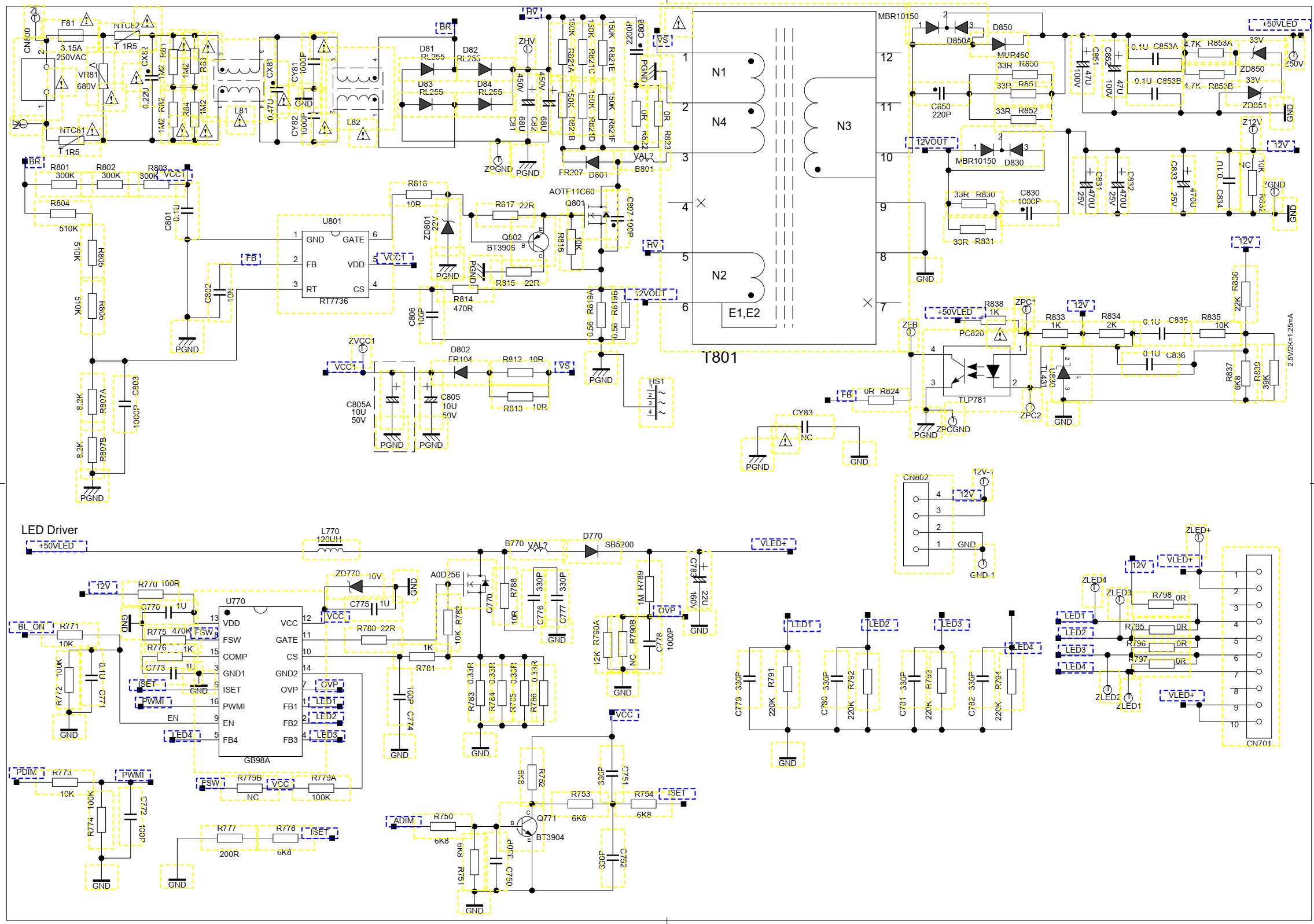
SMPS (Power) schematic

Thursday, 17 September 2020

SAMSUNG UN40H5100AG LED TV – HOW TO UPGRADE THE SOFTWARE, MAIN BOARD CONNECTOR VOLTAGES, HOW TO ENTER THE SERVICE MODE, AND ADJUTMENTS


Samsung Chassis U8KB: Model  UN40H5100AG main board connector voltages, software upgrade, white balance adjustments.  Screen Size (Diagonal)- 40 inches: LCD Panel-FHD 60 Hz

Service Adjustment

You must perform Calibration in the Lattice Pattern before adjusting the White Balance.

Color Calibration:  Adjust Specification

Source- Setting Mode- Pattern -Use Equipment

HDMI 1280 x 720@60 Hz Pattern #24 (Chess Pattern) CA210 & Master MSPG925 Generator

Use other equipment only after comparing the result with that of the Master equipment.

Method of Color Calibration (AV)

1. Apply the NTSC Lattice (N0. 3) pattern signal to the AV IN 1 port.

2. Press the Source key to switch to “AV1” mode.

3. Enter Service mode.

4. Select the “ADC” menu.

5. Select the “AV Calibration” menu.

6. In “AV Calibration Off” status, press the “► ” key to perform Calibration.

7. When Calibration is complete, it returns to the high-level menu.

8. You can see the change of the “AV Calibration” status from Failure to Success.

Method of Color Calibration (Component)

1. Apply the 720p Lattice (N0. 6) pattern signal to the Component IN 1 port.

2. Press the Source key to switch to “Component1” mode.

3. Enter Service mode.

4. Select the “ADC” menu.

5. Select the “Comp Calibration” menu.

6. In “Comp Calibration Off” status, press the “ ►” key to perform Calibration.

7. When Calibration is complete, it returns to the high-level menu.

8. You can see the change of the “Comp Calibration” status from Failure to Success.

Method of Color Calibration (PC)

1. Apply the VESA XGA Lattice (N0. 21) pattern signal to the PC IN port.

2. Press the Source key to switch to “PC” mode.

3. Enter Service mode.

4. Select the “ADC” menu.

5. Select the “PC Calibration” menu.

6. In “PC Calibration Off” status, press the “ ►” key to perform Calibration.

7. When Calibration is complete, it returns to the high-level menu.

8. You can see the change of the “PC Calibration” status from Failure to Success.

Method of Color Calibration (HDMI)

1. Apply the 720p Lattice (N0. 6) pattern signal to the HDMI1/DVI IN port.

2. Press the Source key to switch to “HDMI1” mode.

3. Enter Service mode.

4. Select the “ADC” menu.

5. Select the “HDMI Calibration” menu.

6. In “HDMI Calibration Off” status, press the “►” key to perform Calibration.

7. When Calibration is complete, it returns to the high-level menu.

8. You can see the change of the “HDMI Calibration” status from Failure to Success.

Adjustment

1. Into the Factory Mode.

2. Select SVC Menu.

3. Select ADC/WB menu.

4. Select WB menu.


Software Upgrade

 Software Upgrade can be performed by downloading the latest firmware from samsung.com to a USB memory device.

 Current Version - The software already installed in the TV.  Software is represented as ‘Year/Month/Day_Version’.

How to Check the Software Version

Use the Main Menu

1. Click the "MENU" key in remote controller.

2. Select "Support" menu.

3. Locate the menu cursor "Software Upgrade" menu.

4. Click the "INFO" key.  - Check the Main SW and Micom version.


Use the Factory Mode

How to Upgrade Software and Micom.

Insert a USB drive containing the firmware upgrade downloaded from samsung.com into the TV. Be careful not to disconnect the power or remove the USB drive while upgrades are being applied. The TV will turn off and turn on automatically after completing the firmware upgrade check the firmware version after the upgrades are complete (the new version will have a higher number than the older version). When software is upgraded, video and audio settings you have made will return to their default (factory) settings. It is recommend you write down your settings before beginning firmware update. After update is completed, restore your previous settings.

Main Software Upgrade

1. Store the sw program named "T-NT14LDEUC" in USB memory stick.

- Connect the USB.

2. Click the "MENU" key in Remote Controler.

3. Select "Support" menu.

Locate the menu cursor "Software Update" menu.

4. Locate the menu cursor "Update now" menu.

5. Click the "ENTER" key.

6. Click the "ENTER" key.

- Wait for upgrade complete.

- Check the Software Version.

Main Board connector voltages.

Troubleshooting.

Previous Check.

1. Check the various cable connections first.

- Check to see if there is a burnt or damaged cable.

- Check to see if there is a disconnected or loose cable connection.

- Check to see if the cables are connected according to the connection diagram.

2. Check the power input to the Main Board.

3. Check the power in & output between SMPS & Main Board, Main Board & Panel, IP & Panel.

How to Check Fault Symptom.

Detail Factory Option.

NOTE:  If you replace the main board with new one, please change the factory option as well.  The options you must change are "Type".

Entering Factory Mode

To enter ‘Service Mode’ Press the remote -control keys in this sequence:

if you do not have a remote control:

Power Off > Information > Menu > Mute > Power On

if you have factory remote control: Info > Factory

If you don't have factory remote control, can't control some menus.