REPAIRING AND NOT THROWING AWAY

Richtige Fernseher haben Röhren!

Richtige Fernseher haben Röhren!

In Brief: On this site you will find pictures and technical information about Service Modes, Circuit Diagrams, Firmware Update procedure, Disassemble procedure, Universal remote control set-up codes, Troubleshooting and more....

If you go into the profession, you will obtain or have access to a variety of tech tips databases HERE IT IS Master Electronics Repair !.

These are an excellent investment where the saying: 'time-is-money' rules. However, to learn, you need to develop a general troubleshooting approach - a logical, methodical, method of narrowing down the problem. A tech tip database might suggest: 'Replace C536' for a particular symptom. This is good advice for a specific problem on one model. However, what you really want to understand is why C536 was the cause and how to pinpoint the culprit in general even if you don't have a service manual or schematic and your tech tip database doesn't have an entry for your sick TV or VCR.

While schematics are nice, you won't always have them or be able to justify the purchase for a one-of repair. Therefore, in many cases, some reverse engineering will be necessary. The time will be well spent since even if you don't see another instance of the same model in your entire lifetime, you will have learned something in the process that can be applied to other equipment problems.
As always, when you get stuck, checking out a tech-tips database may quickly identify your problem and solution.In that case, you can greatly simplify your troubleshooting or at least confirm a diagnosis before ordering parts.

Happy repairing!
Today, the West is headed for the abyss. For the ultimate fate of our disposable society is for that society itself to be disposed of. And this will happen sooner, rather than later.

How to use the site:

- If you landed here via any Search Engine, you will get what you searched for and you can search more using the search this blog feature provided by Google. You can visit more posts scrolling the left blog archive of all posts of the month/year,
or you can click on the main photo-page to start from the main page. Doing so it starts from the most recent post to the older post simple clicking on the Older Post button on the bottom of each page after reading , post after post.

You can even visit all posts, time to time, when reaching the bottom end of each page and click on the Older Post button.

- If you arrived here at the main page via bookmark you can visit all the site scrolling the left blog archive of all posts of the month/year pointing were you want , or more simple You can even visit all blog posts, from newer to older, clicking at the end of each bottom page on the Older Post button.
So you can see all the blog/site content surfing all pages in it.

- The search this blog feature provided by Google is a real search engine. If you're pointing particular things it will search IT for you; or you can place a brand name in the search query at your choice and visit all results page by page. It's useful since the content of the site is very large.

Note that if you don't find what you searched for, try it after a period of time; the site is a never ending job !

..............The bitterness of poor quality is remembered long after the sweetness of todays funny gadgets low price has faded from memory........ . . . . . .....
Don't forget the past, the end of the world is upon us! Pretty soon it will all turn to dust!

©2010, 2011, 2012, 2013, 2014 Frank Sharp - You do not have permission to copy photos and words from this blog, and any content may be never used it for auctions or commercial purposes, however feel free to post anything you see here with a courtesy link back, btw a link to the original post here , is mandatory.
All posts are presented here for informative, historical and educative purposes as applicable within fair use. NOTHING HERE IS FOR SALE !

Showing posts with label MAGNAVOX. Show all posts

Tuesday, 11 August 2020

EMERSON LF391EM4 HOW TO ENTER THE SERVICE MODE LCD TV, MAGNAVOX 39ME313V LCD TV – SOFTWARE UPGRADE, SERVICE ADJUSTMENTS, CIRCUIT DIAGRAM


Emerson 39 Inch LCD TV LF391EM4 A, MAGNAVOX 39ME313V-F7 A

How to set up the service mode

1.Turn the power on.
2. Press [MENU] button to display Setup menu.
3. Select “Features”.
4. Select “Software Upgrade”.
5. Select “Current Software Info”.
6. Press [0], [4], [2], [5], [7], [4] and [INFO] buttons on the remote control unit in this order. 

The following screen appears.


Purity Check Mode

This mode cycles through full-screen displays of red, green, blue, and white to check for non-active pixels.
1. Enter the service mode.
2. Each time the [7] button on the remote control unit is pressed, the display changes as follows.

3. To cancel or to exit from the Purity Check Mode, press [CH RETURN] or [PREV CH] button.

The White Balance Adjustment should be performed when replacing the LCD Panel, Digital Main CBA.

Purpose: To mix red and blue beams correctly for pure white.

Symptom of Maladjustment: White becomes bluish or reddish.

Adjustment

1.Operate the unit for more than 60 minutes.
2. Enter the service mode.
3. Press [VOLUME DOWN] button three times on the remote control unit to select “Drive setting” mode.
“Drive” appears in the screen.
4. Set the color analyzer at the CHROMA mode and zero point calibration. Bring the optical receptor pointing at the center of the LCD-Panel.

Note: The optical receptor must be set perpendicularly to the LCD Panel surface.
5. Press [3] button to select the “HDB” for High Drive Blue adjustment. (“HDB” appears in the screen.)

6. Press [MENU] button. The internal Raster signal appears in the screen. (“Internal (Single)” appears in the upper right of the screen as shown below.)

7. Press [CHANNEL UP/DOWN] buttons to adjust the color temperature becomes 12000°K (x= 0.272  y= 0.278 ± 0.003).
8. Press [1] button to select the “HDR” for High Drive Red adjustment (“HDR” appears in the screen.) and press [CHANNEL UP/DOWN] buttons to adjust the color temperature.
9. If necessary, adjust the “HDB”, “HDR” again.
10. Press [6] button to select the “LDB” for Low Drive Blue adjustment (“LDB” appears in the screen.) and press [CHANNEL UP or DOWN] buttons to adjust the color temperature.

11. Press [4] button to select the “LDR” for Low Drive Red adjustment (“LDR” appears in the screen.) and press [CHANNEL UP or DOWN] buttons to adjust the color temperature.
12. If necessary, adjust the “LDB”, “LDR” again.
13. Press [VOLUME DOWN] button to shift to the “Debugging Message” mode.  If there is no message under “[WB]” section, this adjustment completes.
If “Drive settings are NG. Retry again.” Is displayed, repeat above steps from 5. to 12. Then check “Debugging Message” again. If “Drive settings are NG. Retry again.” is displayed, replace the LCD Panel or Digital Main CBA.

14. To cancel or to exit from the White Balance Adjustment, press [CH RETURN] or [PREV CH] button.

How to initialize the LCD TV

The purpose of initialization is to place the set in a new out of box condition. The customer will be prompted to select a language and program channels after the set has been initialized.
To put the program back at the factory-default, initialize the LCD TV using the following procedure.

NOTE: Disconnect any device from the USB Port before you conduct on this procedure.

Turn the power on.
2. Enter the service mode.
- To cancel the service mode, press [ Power ] button on the remote control unit.
3. Press [BACK] button to enter the Control Panel Key Confirmation Menu.
4. Press any button on the control panel.
5. Press [INFO] button to proceed with the self check mode.
6. Make sure to confirm the “INITIALIZED FINISH” appears in the green screen.
7. Unplug the AC Cord and plug it back on again.

FIRMWARE RENEWAL MODE

User Upgrade
(Filename example: TVNB012_00_UF_XX91_BC.ecc or TVNB2001_00_UH_XX91_BB1.bin)
Upgrade the firmware only. The setting values will not be initialized.
The User Upgrade and the Firmware Upgrade (Factory Upgrade) will be done by the same file. If you want to upgrade the firmware and initialize the setting values also, add “FACT_” at the beginning of the filename.
If you want to upgrade the firmware only and leave the setting values as they are, eliminate the “FACT_” from the filename.

Update procedure
1. Turn the power on.
2. Press [MENU] button to display Menu.
3. Select “Features”.
4. Select “Software Upgrade”.
5. Select “Upgrade” to display Upgrade screen.
6. Press [OK] button to display Software Upgrade screen.
7. Select “USB” and press [OK] button.
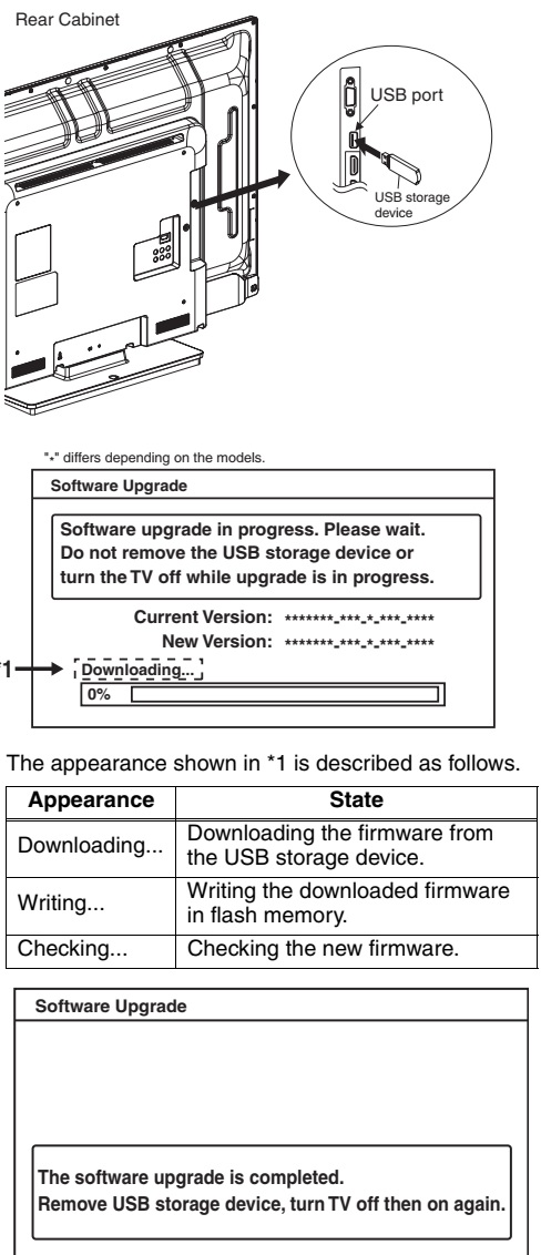
8. Insert the USB storage device to the USB port as shown below.

9. Select “Check” and press [OK] button.
10. Select “Upgrade” and press [OK] button to start software upgrade.

11. The update will start and the following will appear in the screen.

Note: If the screen isn’t displayed, repeat from step 1.

12. When the firmware update is completed, the following will appear in the screen.

Remove the USB storage device from the USB port.
Turn the power off and turn the power on again.
Factory Upgrade (Firmware Upgrade/Flash Upgrade)

Firmware Upgrade
(Filename example: FACT_TVNB012_00_UF_XX91_BC.ecc or FACT_TVNB2001_00_UH_XX91_BB1.bin)
Upgrade the firmware and initialize the setting values.
The User Upgrade and the Firmware Upgrade (Factory Upgrade) will be done by the same file. If you want to upgrade the firmware and initialize the setting values also, add “FACT_” at the beginning of the filename.
If you want to upgrade the firmware only and leave the setting values as they are, eliminate the “FACT_” from the filename.

Flash Upgrade
(Filename example: ALL_TVNB012_00_UF_XX91_BC.ecc or ALL_TVNB2001_00_UH_XX91_BB1.bin)
Upgrade the firmware and initialize the setting values along with the factory default such as White Balance, etc.
Before the upgrade, you will need to make a note of all the factory default so you will be able to set it back on the TV after the initialization.
The Flash Upgrade will be done by it's unique file.
The User Upgrade/Firmware Upgrade (Factory Upgrade) file cannot be used for this upgrade.

Update procedure
1. Turn the power off.
2. Insert the USB storage device to the USB port as shown below.

3. Turn the power on.
4. The update will start and the following will appear in the screen.

If the screen isn’t displayed, repeat from step 1.

5. When the firmware update is completed, the following will appear in the screen.

Remove the USB storage device from the USB port.
Turn the power off and turn the power on again.
Service mode initial screen with a word “INITIALIZED” will appear in the screen. The color of the word “INITIALIZED” will change from red to green when initialization is completed.

Power supply (SMPS) schematic

CAUTION: Fixed voltage (or Auto voltage selectable) power supply circuit is used in this unit.  If Main Fuse (F602) is blown , check to see that all components in the power supply circuit are not defective before you connect the AC plug to the AC power supply.  Otherwise it may cause some components in the power supply circuit to fail.

Because a hot chassis ground is present in the power supply circuit, an isolation transformer must be used when repairing.
Also, in order to have the ability to increase the input slowly, when troubleshooting this type of power supply circuit, a variable isolation transformer is required.


Digital main schematic


Function CBA

Friday, 24 April 2020

PHILIPS, MAGNAVOX, SYLVANIA AND EMERSON 40 INCH LCD TVS HOW TO ENTER THE SERVICE MODE, SERVICE MODE ADJUSTMENTS - TROUBLESHOOTING - SMPS SCHEMATIC

Electrical adjustments

Test Equipment Required
NTSC Pattern Generator (Color Bar W/White Window, Red Color, Dot Pattern, Gray Scale, Monoscope, Multi-Burst)
Remote control unit
Color Analyzer
How to set up the service mode
Turn the power on.
2. Press [MENU] button to display Setup menu.
3. Select “Features”.
4. Select “Current Software Info”.
5. Press [0], [4], [2], [5], [7], [4] and [Info] buttons on the remote control unit in this order. The following screen appears.
Purity Check Mode
This mode cycles through full-screen displays of red, green, blue, and white to check for non-active pixels.
1. Enter the Service mode.
2. Each time pressing [7] button on the remote control unit, the display changes.
3. To cancel or to exit from the Purity Check Mode, press [PREV CH] button.

Applicable to:
40”
40”
40”
40”
40”
40”
40MF430B/F7
40MF430B/F7
LC407SS1
LC407SS1
LC407SS1
LC407EM1
MAGNAVOX
MAGNAVOX
SYLVANIA
SYLVANIA
SYLVANIA
EMERSON
(Serial No. : DS1A)
(Serial No. : DS2A)
(Serial No. : DS1A)
(Serial No. : DS2A)
(Serial No. : DS3A)

The White Balance Adjustment should be performed when replacing the LCD Panel or Digital Main CBA.
Symptom of Maladjustment: White becomes bluish or reddish.
Operate the unit for more than 20 minutes.
2. Input the White Raster (70%=70IRE, 40%=40IRE).
3. Set the color analyzer to the CHROMA mode and bring the optical receptor to the center on the LCD-Panel surface after zero point calibration as shown above.
Note: The optical receptor must be set perpendicularly to the LCD Panel surface.
4. Enter the Service mode. Press [VOLUME DOWN] button on the remote control unit and select “C/D” mode.
5. [CUTOFF]
Press [1] button to select “COR” for Red Cutoff adjustment. Press [3] button to select “COB” for Blue Cutoff adjustment.
[DRIVE]
Press [4] button to select “DR” for Red Drive adjustment. Press [6] button to select “DB” for Blue Drive adjustment.
6. In each color mode, press [CHANNEL UP/DOWN] buttons to adjust the values of color.
7. Adjust Cutoff and Drive so that the color temperature becomes 12000°K (x= 0.272 / y= 0.278 ±0.005).
8. To cancel or to exit from the White Balance Adjustment, press [PREV CH] button.
How to initialize the LCD TV
The purpose of initialization is to place the set in a new out of box condition. The customer will be prompted to select a language and program channels after the set has been initialized.
To put the program back at the factory-default, initialize the LCD TV using the following procedure.
1. Turn the power on.
2. Enter the service mode.
- To cancel the service mode, press [POWER] button on the remote control unit.
3. Press [INFO] button on the remote control unit to initialize the LCD television.
4. "INITIALIZED" will appear in the upper right of the screen. "INITIALIZED" color will change to green from red when initializing is completed.
Firmware renewal
Equipment Required
a. USB storage device
b. Remote Control Unit
[There are two states (the User Upgrade and the Factory Upgrade) in firmware update.]
User Upgrade > Upgrade the firmware only.  The setting values are not initialized.
Factory upgrade > Upgrade the firmware and initialize the setting values.
The identification of User Upgrade and Factory Upgrade are done by the filename.
1. Turn the power off and unplug the AC Cord.
2. Insert the USB storage device to the USB port as shown below.
The USB port “SERVICE TERMINAL” will be blocked by a cross shaped piece of plastic. Cutoff both end of the plastic connected to the PCB Holder as illustrated below.
3. Plug the AC cord in the wall outlet and turn the power on.
4. The update will start and the following will appear on the screen.
Note: If the screen isn’t displayed, repeat from step 1
5. When the firmware update is completed, the following will appear on the screen.
Remove the USB storage device from the USB port.
Turn the power off and turn the power on again.
[When the Factory Upgrade is used, after restarting TV, shift to initial screen menu in service mode. "INITIALIZED" will appear on the upper right of the screen. "INITIALIZED" color will change to green from red when initializing is completed.]
Troubleshooting table
SMPS [Power supply schematic]
Fixed voltage (or Auto voltage selectable) power supply circuit is used in this unit.  If Main Fuse (F1601) is blown , check to see that all components in the power supply circuit are not defective before you connect the AC plug to the AC power supply.
Otherwise it may cause some components in the power supply circuit to fail.
Power Supply 1 Schematic Diagram
Power Supply 2 Schematic Diagram
Power Supply 3 Schematic Diagram

Friday, 29 November 2019

LG LCD TV 42DL550 HOW TO REPAIR AN LG LCD TV MAIN BOARD

Symptoms
The TV would power on and the LG Logo screen with the clock would appear. It would freeze on the logo screen. It was stuck there and would not boot any further. The none of the buttons would work. It was totally stuck.


First I tried unplugging it for about 15 min to reset everything, but that did not make a difference. Note: It’s always good to try this first on any electronic device. Also if the device has any kind of factory reset button, always try that as well before taking it apart.
I searched around online and found other people reporting issues with this TV. HDMI ports not working, no inputs working, Lines on the screen, fuzzy video, etc… It seems many different makes and models are affected.


I removed the board and I did not see any physical damage, no components looked fried or burnt, no capacitors looked bad, and all the connectors looked to good. This lead me to believe the main control board Model EBT60955753 LG MAIN (3642-1052-0150) could have one or more bad solder joints.
This TVs was purchased in 2010 and out of warranty. A new board was hard to find, and too expensive. 


Attempt at your own risk!  This will void your warranty, and possibly damage the board.  I have only tested this on an LG 42DL550!  Other readers have had success on different models so search through the comments.  I would only try this if the TV is unusable and you have nothing to lose!


Summary

To fix it, I baked the main board in a electric oven for about 10 minutes at around 385 °F and It worked!

Explanation

Why did this work? After heating and cooling for years, tiny cracks can form in the solder connections.  Heating the board to 385° F (above the solder melting point) caused the solder to melt and these cracks flow back together.
Believe it or not, this trick works on more than just this TV.  This can fix a long list of other electronics.  It’s not uncommon for manufactures to under cool their components, and/or ship electronics with bad solder.  Poor ventilation, bad fans, small heat sinks, dust, stress, and other factors can also cause over heating or cracked solder points.  Even a very tiny crack that you can not see can cause a bad connection.

Warning:  Attempt at your own risk!  Safety First! Always wear protective gear when working on electronics.  Safety Glasses, Gloves, etc…  Remove Electricity from the device (unplug) to Avoid Shock!


Again, attempt at your own risk!  This will void your warranty, and possibly damage the board.  I have only tested this on an LG 42DL550!  Other readers have had success on different models so search through the comments.  I would only try this if the TV is unusable and you have nothing to lose!


Let’s Do This!  Step-By-Step DIY Fix:


– Remove the board from the TV


LG LED TV Control Board EBT60955753 
(3642-1052-0150)

  • Step 1.  Call LG and complain.  Everyone complaining to LG might make them understand how unhappy people are, and they’ll see this is a known issue!  Maybe if you play your card right, they will admit this is a fault with their product and send you a replacement.

  • Step 2.  UNPLUG THE TV before you touch it!  Electric shock can cause death!
  • Lay the TV down on its face. (Put it on a blanket to be careful not to scratch the LCD)
  • Remove the stand from the TV. (remove the four long screws at bottom and the stand slides out)
  • Remove the back cover from the TV.  (don’t forget the screw near the power plug, and the one in the middle of the input jacks.)
  • Take pictures of the Board from all angles.  Make sure to get good ones of all the connections.  You can use these pictures later to make sure you reinstall it correctly.
  • Remove all the connections. (Be gentle, they should come off easy, if you are doing it correctly)
    • How to disconnect them isn’t obvious to the inexperienced.  Use the picture above for reference. (Click on the picture to enlarge it!)
    • On the upper right there are two ribbon cables. To disconnect these, gently lift the thin black plastic strip on the connector (it flips up), then you can pull the ribbon cables out.
    • On the lower right there’s a wide header block with gray wires. Squeeze the sides (opposite ends) of the connector to release it and pull up.
    • On the upper left are two other connectors. In the center of these is a small plastic part. Press down gently on the edge of that (the edge near the wires), causing the opposite edge to lift a bit to unlatch. While pressing, pull gently in the direction of the wires, away from the board.
  • Once all the wires are disconnected remove the six (6) screws holding the main board to the frame.
  • Remove the black plastic face plate from the side input jacks. (No screws, it’s held on by it’s plastic clips).

– Bake The Board


  • Now we are going to bake it in a conventional electric oven.  (Do NOT use a microwave, gas oven, open flames, Air Forced Heat, or any other type of heat!)
  • Why not use a heat gun?  A heat gun is forced air like a hair dryer.  As soon as the solder melts, the air will blow the components out of place, or even go flying off the board.
  • Why not use a gas oven?  Open flames can be dangerous in this situation.
  • Why not use a microwave?  Never put metal in a microwave!  Very bad things can happen.
  • Preheat the oven to 385 °F (196 °C)
    • The correct Temperature is IMPORTANT.  If you don’t trust the temperature setting on your oven, or if your oven does not have a temperature setting, then get a baking thermometer and test your oven!
    • 385 °F is working for most people, but there are different kinds of solder.  Altitude and humidity might also play a factor.  Most solder melts between 360 and 419 Degrees Fahrenheit or 180 – 215 Degrees Celsius.
    • Solder is a mixture of Tin and Lead.
      50 Tin/50 Lead: melts between 183–215 °C (361–419 °F)
      60 Tin/40 Lead: melts between 183–190 °C (361–374 °F)
    • NOTE:  These temperatures might sound scary, but the ignition temperature of paper is around 451 °F so these components should not be damaged at these temps in an electric oven.  Again, this is why we only us an electric oven.  No open flames!
    • See https://en.wikipedia.org/?title=Solder for more details about Solder.
  • Place the board face up on something nonmetallic like a piece of cardboard.  A pizza round or similar works well. (Do not put it on anything metal because the solder will stick to it.)
  • Place it on the center rack of the oven.
  • It will smell funky when cooking so you might want to open a window and/or turn on a fan!
  • Let it cook for about 10 min.
  • Turn the oven off and let it cool.  (Be careful!  It’s hot and will burn you!  Use oven mitts!)
    • Do not to bump or disturb it while it is cooling!
    • I would not move it until its below 300 °F, so you don’t disturb any components!
    • Just turn the oven off and leave the board in it with the door open until it’s cooled off a bit.
    • If you take it out of the oven while it is still hot, remove the board very carefully, let it cool at least 30 min before you touch it.

– Install and Test


  • Install the main board in the reverse order that you removed it. (Refer to your pictures)
    • Make sure you get all the cables in the correct location.
    • Double check each cable to make sure it’s connected correctly.
    • Check your pictures to make sure you have everything correct.
    • You might want to leave the back off until you test it in case it doesn’t work, and you need to bake it again. Just do NOT touch anything back there with it plugged in!  BE SAFE!
  • Turn on the TV and see if it works.  (Note:  Wait at least 10 Seconds after turning it on because it seems to take a long time for this particular TV come on.)
  • If it does not work:
    • Try cooking it again for 15 min.
    • 10 min. worked for me on the first try but results my vary…
    • Try a higher temperature 183 – 215 °C (361 – 419 °F) as noted above.
    • One reader noted he went all the way up to 482 °F (250 °C ) although I highly recommend staying below 425 °F.  I’m guessing his oven settings are off.
    • Another reader said he put a weight on the LVDS chip while baking and that worked.
    • Read through the comments, there’s a lot of good info in there.
Please comment to let everyone know how it went for you!  Include the Make and Model of your TV / electronic device to help others can find this post!

Warning:  Attempt at your own risk!  Safety First! Always wear protective gear when working on electronics.  Safety Glasses, Gloves, etc…  Remove Electricity from the device (unplug) to Avoid Shock!


Again, attempt at your own risk!  This will void your warranty, and possibly damage the board.  I have only tested this on an LG 42DL550!  Other readers have had success on different models so search through the comments.  I would only try this if the TV is unusable and you have nothing to lose!

Thursday, 11 April 2019

SYLVANIA LC220SS2 - EMERSON LC220EM2 - MAGNAVOX 22ME601B - SERVICE MODE – VCOM ADJUSTMENT – INITIALIZATION – FIRMWARE UPDATE

SYLVANIA LC220SS2 - EMERSON LC220EM2 - MAGNAVOX 22ME601B - Service mode – Vcom adjustment – Initialization – firmware update

Service mode:
1. Turn the power on.
2. Press [MENU] button to display Setup menu.
3. Select “Features”.
4. Select “Current Software Info”.
5. Press [0], [4], [2], [5], [7], [4] and [INFO] buttons on the remote control unit in this order. The following screen appears.
1. Purity Check Mode
This mode cycles through full-screen displays of red, green, blue, and white to check for non-active pixels.
1. Enter the Service mode.
2. Each time the [7] button on the remote control unit is pressed , the display changes.
3. To cancel or to exit from the Purity Check Mode, press [CH RETURN] or [PREV CH] button.
VCOM Adjustment
1. Operate the unit for more than 60 minutes.
2. Set the color analyzer at the zero point calibration and bring the optical receptor pointing at the center of the LCD-Panel.
Note: The optical receptor must be set perpendicularly to the LCD Panel surface.
3. Enter the Service mode.
4. Press [3] button on the remote control unit.
5. Press [CHANNEL UP/DOWN] buttons on the remote control unit so that the color analyzer value becomes minimum.
6. To cancel or to exit from the VCOM Adjustment, press [CH RETURN] or [PREV CH] button.
The White Balance Adjustment should be performed when replacing the LCD Panel
or Digital Main CBA.
3. White Balance Adjustment
Purpose: To mix red and blue beams correctly for pure white.
Symptom of Misadjustment: White becomes bluish or reddish.
ITEM SPECIFICATION
Color temperature x= 0.272 +/-0.002
y= 0.278 +/- 0.002
Input Signal Internal pattern
(40/70% raster)
Measurement point Screen center
M. EQ. CA-310 (KONICA MINOLTA
Luminance meter) or
measuring instrument as
good as CA-310.
Aging time 60min.
(Retail MODE/100IRE Raster
HDMI 1080i@60)
MODE setting of TV Shipment setting/ Retail MODE
Ambient
temperature 25 degreeC ± 5 degreeC
1. Operate the unit for more than 60 minutes.
2. Enter the Service mode.
3. Press [VOLUME DOWN] button three times on the remote control unit to select “Drive setting” mode. “Drive” appears on the screen.
4. Set the color analyzer at the CHROMA mode and zero point calibration. Bring the optical receptor pointing at the center of the LCD-Panel.
Note: The optical receptor must be set perpendicularly to the LCD Panel surface.
5. Press [3] button to select the “HDB” for High Drive Blue adjustment. (“HDB” appears on the screen.)
6. Press [MENU] button. The internal Raster signal appears on the screen. (“Internal (Single)” appears on the upper right of the screen as shown below.)
7. Press [CHANNEL UP/DOWN] buttons to adjust the color temperature becomes 12000 degree K (x= 0.272 / y= 0.278 ±0.002).
8. Press [1] button to select the “HDR” for High Drive Red adjustment (“HDR” appears on the screen.) and press [CHANNEL UP/DOWN] buttons to adjust the color temperature.
9. If necessary, adjust the “HDB” or “HDR” again.
10. Press [6] button to select the “LDB” for Low Drive Blue adjustment (“LDB” appears on the screen.) and press [CHANNEL UP/DOWN] buttons to adjust the color temperature.
11. Press [4] button to select the “LDR” for Low Drive Red adjustment (“LDR” appears on the screen.) and press [CHANNEL UP/DOWN] buttons to adjust the color temperature.
12. If necessary, adjust the “LDB” or “LDR” again.
13. Press [VOLUME DOWN] button to shift to the “Debugging Message” mode.
If there is no message under “[WB]” section, this adjustment completes. If “Drive settings are NG. Retry.” is displayed, repeat above steps from 5. to 12. Then check
“Debugging Message” again. If “Drive settings are NG. Retry.” is displayed, replace the LCD Panel or Digital Main CBA.
14. To cancel or to exit from the White Balance Adjustment, press [CH RETURN] or [PREV CH] button.
INITIALIZE THE LCD TV
The purpose of initialization is to place the set in a new out of box condition. The customer will be prompted to select a language and program channels after the set has been initialized.
To put the program back at the factory-default, initialize the LCD TV using the following procedure.
1. Turn the power on.
2. Enter the service mode.
- To cancel the service mode, press [POWER] button on the remote control unit.
3. Press [FREEZE] button on the remote control unit to initialize the LCD television.
4. "INITIALIZED" will appear in the upper right of the screen. "INITIALIZED" color will change to green from red when initializing is completed.
Firmware Update Procedure
1. Turn the power off and unplug the AC Cord.
2. Insert the USB storage device to the USB port
3. Plug the AC cord in the wall outlet and turn the power on.
4. The update will start and appear on the screen.
5. When the firmware update is completed, Remove the USB storage device from the USB port. Turn the power off and turn the power on again will appear on the screen.
Note:
When the Factory Upgrade is used, after restarting TV, shift to initial screen menu in service mode. "INITIALIZED" will appear on the upper right of the screen. "INITIALIZED" color will change to green from red when initializing is completed.

Wednesday, 10 April 2019

SYLVANIA, EMERSON AND MAGNAVOX 19 INCH LCD TV – HOW TO ENTER SERVICE MODE, ADJUSTMENTS, INITIALIZATION AND SCHEMATICS AND MORE

Sylvania, Emerson and Magnavox 19 inch LCD TV – How to enter service mode, adjustments, initialization and more

Applicable to: Sylvania LC195SLX, Emerson LC195EMX, Magnavox 22MF339B/F7 and many more models of these brands 19 inch LCD TVs. HOW TO INITIALIZE THE LCD TV
The purpose of initialization is to place the set in a new out of box condition. The customer will be prompted to select a language and program channels after the set has been initialized.
To put the program back at the factory-default, initialize the LCD TV using the following procedure.
1. Turn the power on.
2. To enter the service mode, press the service button on the service remote control unit.
- To cancel the service mode, press [POWER] button on the service remote control unit.
3. Press [INFO] button on the service remote control unit to initialize the LCD television.
4. "INITIALIZED" will appear in the upper right of the screen. "INITIALIZED" color will change to green from red when initializing is complete.
FIRMWARE RENEWAL MODE
Equipment Required
a. USB memory
b. Remote Control Unit
Firmware Update Procedure
Note: There are two states (the User Upgrade and the Factory Upgrade) in firmware update.
The identification of User Upgrade and Factory
Upgrade are done by the filename.
1. Turn the power off and unplug the AC Cord.
2. Insert the USB memory to the USB port.
3. Plug the AC cord in the wall outlet and turn the power on.
4. The update will start and the following will appear on the screen.
“Software upgrade in progress. Please wait.
Do not remove the USB device or turn the TV off while upgrade is in progress”
If the above screen isn’t displayed, repeat from step 1
5. When the firmware update is completed, the screen will be displayed.
Unplug the AC cord and kindly remove the USB memory from the USB port. Plug the AC cord in the wall outlet again and turn the power on.
Note:
When the Factory Upgrade is used, after restarting TV, shift to initial screen menu in service  mode. "INITIALIZED" will appear on the upper right of the screen. "INITIALIZED" color will change to green from red when initializing is complete.
Service mode
Electrical adjustments are required after replacing circuit components and certain mechanical parts. It is important to perform these adjustments only after all repairs and replacements have been completed.  Also, do not attempt these adjustments unless the proper equipment is available.
Test Equipment Required
1. NTSC Pattern Generator (Color Bar W/White Window, Red Color, Dot Pattern, Gray Scale, Monoscope, Multi-Burst)
2. Remote control unit
3. Color Analyzer.
How to make the Service remote control unit:
[LC195SLX, LC195EMX]
Cut “A” portion of the attached remote control unit as shown in Fig.
[22MF339B/F7, 19MF339B/F7]
Cut “A” portion of the attached remote control unit as shown in Fig.
[LC225SSX, LC195SSX]
Cut “A” portion of the attached remote control unit as shown in Fig.
How to set up the service mode:
How to enter the Service mode:
1. Use the service remote control unit.
2. Turn the power on.
3. Press the service button on the service remote control unit. The service mode screen appears.
LC195SLX, LC195EMX, LC195SSX, 19MF339B/F7 – SMPS section schematic
22MF339B/F7, LC225SSX – Back-light inverter schematic
22MF339B/F7, LC225SSX – SMPS section schematic
Purity Check Mode
This mode cycles through full-screen displays of red, green, blue, and white to check for non-active pixels.
1. Enter the Service mode.
2. Each time pressing [7] button on the service remote control unit, the display changes as follows.
VCOM Adjustment

1. Operate the unit for more than 20 minutes.
2. Set the color analyzer and bring the optical receptor to the center on the LCD-Panel surface after zero point calibration.
Note: The optical receptor must be set perpendicularly to the LCD Panel surface.
3. Enter the Service mode.
4. Press [3] button on the service remote control unit.
5. Press [CHANNEL UP/DOWN] buttons on the service remote control unit so that the color analyzer value becomes minimum.
The white balance adjustment should be performed when replacing the LCD Panel or Digital CBA.
3. White Balance Adjustment
Purpose: To mix red, green and blue beams correctly for pure white.
Symptom of Maladjustment: White becomes bluish or reddish.
Operate the unit for more than 20 minutes.
2. Input the White Raster(70%=70IRE, 40%=40IRE).
3. Set the color analyzer to the CHROMA mode and bring the optical receptor to the center on the LCD-Panel surface after zero point calibration.
Note: The optical receptor must be set perpendicularly to the LCD Panel surface.
4. Enter the Service mode. Press [VOLUME DOWN] button on the service remote control unit and select “C/D” mode.
5. [CUTOFF]
Press [1] button to select “COR” for Red Cutoff adjustment. Press [3] button to select “COB” for Blue Cutoff adjustment.
[DRIVE]
Press [4] button to select “DR” for Red Drive adjustment. Press [6] button to select “DB” for Blue Drive adjustment.
6. In each color mode, press [CHANNEL UP/DOWN] buttons to adjust the values of color.