REPAIRING AND NOT THROWING AWAY

Richtige Fernseher haben Röhren!

Richtige Fernseher haben Röhren!

In Brief: On this site you will find pictures and technical information about Service Modes, Circuit Diagrams, Firmware Update procedure, Disassemble procedure, Universal remote control set-up codes, Troubleshooting and more....

If you go into the profession, you will obtain or have access to a variety of tech tips databases HERE IT IS Master Electronics Repair !.

These are an excellent investment where the saying: 'time-is-money' rules. However, to learn, you need to develop a general troubleshooting approach - a logical, methodical, method of narrowing down the problem. A tech tip database might suggest: 'Replace C536' for a particular symptom. This is good advice for a specific problem on one model. However, what you really want to understand is why C536 was the cause and how to pinpoint the culprit in general even if you don't have a service manual or schematic and your tech tip database doesn't have an entry for your sick TV or VCR.

While schematics are nice, you won't always have them or be able to justify the purchase for a one-of repair. Therefore, in many cases, some reverse engineering will be necessary. The time will be well spent since even if you don't see another instance of the same model in your entire lifetime, you will have learned something in the process that can be applied to other equipment problems.
As always, when you get stuck, checking out a tech-tips database may quickly identify your problem and solution.In that case, you can greatly simplify your troubleshooting or at least confirm a diagnosis before ordering parts.

Happy repairing!
Today, the West is headed for the abyss. For the ultimate fate of our disposable society is for that society itself to be disposed of. And this will happen sooner, rather than later.

How to use the site:

- If you landed here via any Search Engine, you will get what you searched for and you can search more using the search this blog feature provided by Google. You can visit more posts scrolling the left blog archive of all posts of the month/year,
or you can click on the main photo-page to start from the main page. Doing so it starts from the most recent post to the older post simple clicking on the Older Post button on the bottom of each page after reading , post after post.

You can even visit all posts, time to time, when reaching the bottom end of each page and click on the Older Post button.

- If you arrived here at the main page via bookmark you can visit all the site scrolling the left blog archive of all posts of the month/year pointing were you want , or more simple You can even visit all blog posts, from newer to older, clicking at the end of each bottom page on the Older Post button.
So you can see all the blog/site content surfing all pages in it.

- The search this blog feature provided by Google is a real search engine. If you're pointing particular things it will search IT for you; or you can place a brand name in the search query at your choice and visit all results page by page. It's useful since the content of the site is very large.

Note that if you don't find what you searched for, try it after a period of time; the site is a never ending job !

..............The bitterness of poor quality is remembered long after the sweetness of todays funny gadgets low price has faded from memory........ . . . . . .....
Don't forget the past, the end of the world is upon us! Pretty soon it will all turn to dust!

©2010, 2011, 2012, 2013, 2014 Frank Sharp - You do not have permission to copy photos and words from this blog, and any content may be never used it for auctions or commercial purposes, however feel free to post anything you see here with a courtesy link back, btw a link to the original post here , is mandatory.
All posts are presented here for informative, historical and educative purposes as applicable within fair use. NOTHING HERE IS FOR SALE !

Showing posts with label CD. Show all posts

Thursday, 8 October 2020

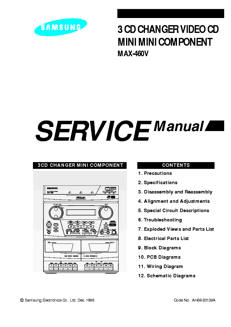
SAMSUNG MAX-460V 3 CD CHANGER VIDEO CD MINI COMPONENT HOW TO DO ADJUSTMENTS, HOW TO TAKE OUT THE DISC IN EMERGENCY, CIRCUIT DESCRIPTIONS, SCHEMATIC

https://elektrotanya.com/PREVIEWS/63463243/23432455/samsung/samsung_max-460v.pdf_1.png How to take out the CD at emergency

1. If power is connected:

- Turn power on.

- Open the tray using the open/close key.

- Remove the Door in the direction of arrow.

2. If power is not connected:

- Turn the gear clockwise using a screw driver as shown in Figure.

- Pull the Tray in the direction of arrow @ and then remove the Door in the direction of arrow.

Tuner adjustment points

Cassette deck adjustments

Test Equipment needed

1. Oscilloscope

2. VTVM

TAPE

1. MTT-111 (or equivalent) : Test tape on which 3KHz signal is recorded (Tape speed adjustment)

2. MTT-5512 (or equivalent)

3. MTT-113CN (or equivalent) : Test tape on which 8KHz signal is recorded (Azimuth)

4. MTT-112B (or equivalent) : Test tape on which 1KHz signal is recorded (L.R. channel unbalance)

Adjustment Procedure

Tracing gain adjustment

Special circuit descriptions

RF Amp (KA9220) : NIC9220

RF I-V Amp(1) and RF I-V Amp(2) currents are converted to voltage via internal resistance of 58k½ from the current of PD1(A+C) and PD2(B+D):

These voltage are added by the RF summing amplifier. The signal (A+B+C+D) is applied to RFO (No. 2 terminal).

RF output voltage is calculated as follows :

VRF= -R3 x (iPD1 + iPD2)

VRF= -R3 x (V1/R1 + V2/R2)

VRF= -R3 x ( + )

VRF= - x (V1 + V2)

FOCUS ERROR Amp(KA9220) : NIC9220

FOCUS ERROR Amp amplifies the difference between RF I-V Amp(1) output (A+C) and RF I-V Amp(2) output(B+D).

These two signals are supplied to (-) and (+) input terminals of FOCUS ERROR Amp. The FOCUS ERROR output is applied to FE (Terminal No.57).

The FE output voltage of this low frequency component varies according to {(A+C) - (B+D)}.

VFE is calculated as follows:

VFE = (R2/R1) x (V2-V1) = 5.4(V2-V1)

This FOCUS ERROR voltage is sent to FOCUS SERVO .

FOCUS SERVO SYSTEM (KA9220) : NIC9220

When FS3 is ON, high frequency gain decreases (time constant set by pin17, pin19 ; capacitor is connected to internal resistance).

The capacitor between pin 18 and GND sets the time constant to pass the low frequencies in PLAY mode.

The maximum frequency of the focus phase compensation is inversely proportional to the resistance connected to pin 7. Focus search peak is about 1.1 Vp-p, and is inversely proportional to the resistance connected to pins 22,23

(if this resistance changes, the peak of track jump and sled kick change).

The inverted input of FZC comparator is set to 5.7% of the difference between Vcc and VC(pin69) {{5.7% x (Vcc-Vc)}.

Note : If the resistance connected to pin7 changes, the phase compensation peak of the focus tracking sled servos change. (The 'op-amp' dynamic range and offset voltage also change.)

TRACKING SLED SERVO SYSTEM (KA9220) : NIC9220

The capacitor between pin 15 and 16 attenuates high frequencies when TG2 is off. The maximum frequency of tracking phase compensation is inversely proportional to the resistance connected to pin 7 (about 1.2kHz at 470k).

The tracking jump (FWD and REV) is determined when TM3 and TM4 are ON, and the peak voltage induced from the tracking coil is determined by both TM3 and TM4 currents and the feed back resistance of pin 47.

Track jump max voltage = TM3 (TM4) current x feedback resistance.

FWD or REV sled kick occurs when TM5 or TM6 is ON, and the peak voltage added to sled motor (determined by TM5 or TM6 current and the feedback resistance of pin 41.)

Sled jump max. voltage = TM5(TM6) current x feedback resistance.

Each SW current is determined by the resistance connected to pin 22 and 23.

When the resistance is about 150½,

TM3 or TM4 = 11µA,

TM5 or TM6 = 22µA,

This current is inversely proportional to the resistor, variable within a range of t 5 to 40 µA for TM3.

STOP is the ON/OFF detection signal for the limit SW (or the sled motor's innermost circumference).

CD Pack Exploded View

Schematic diagram-Main board

Front board schematic

CD board schematic

Video CD board schematic

PCBs


Friday, 18 September 2020

SONY HCD CPZ1DAB EXPLODED VIEW, PART NAMES

Sony HCD CPZ1DAB exploded view, part names Compact Disc Deck Receiver

 CASE SECTION disassembly

MECHANICAL DECK (TAPE) SECTION disassembly
FRONT PANEL SECTION

LID (TC) SECTION

CHASSIS SECTION
AMP/POWER SECTION

HCD-CPZ1DAB CD MECHANISM DECK SECTION-1 (CDM80BH-K6BD83S-WD)

 CD MECHANISM DECK SECTION-2 (CDM80BH-K6BD83S-WD)

CD MECHANISM DECK SECTION-3 (CDM80BH-K6BD83S-WD)

BASE UNIT SECTION (BU-K6BD83S-WD)

SONY HCD CPZ1DAB SERVICE MODE, ERROR CODE MODE, TEST MODE, RESET, ADJUSTMENT PROCEDURE

COMPACT DISC DECK RECEIVER Sony HCD CPZ1DAB service mode, error code mode, test mode, Reset, adjustment procedure and more


HCD-CPZ1DAB is the amplifier, CD player, tape deck and tuner section in CMT-CPZ1DAB.
CD Mechanism Type  CDM80BH-K6BD83S-WD
Base Unit Name  BU-K6BD83S-WD
Optical Pick-up Block Name  KSM-213DCP
Model Name Using Similar Mechanism  HCD-CPZ1
Tape Transport Mechanism Type  CMAL1Z255A
Ampler section
DIN power output (rated): 60 + 60 W (4 ohms at 1 kHz, DIN)
Continuous RMS power output (reference): 75 + 75 W (4 ohms at 1 kHz, 10% THD)
Outputs
CD DIGITAL OUT: Optical Wavelength: 660 nm
PHONES (stereo mini jack): Accepts headphones with an impedance of 8 ohms or more
SPEAKER: Accepts impedance of 4 ohms
The laser diode in the optical pick-up block may suffer electrostatic break-down because of the potential difference generated by the charged electrostatic load, etc. on clothing and the human body.
During repair, pay attention to electrostatic break-down and also use the procedure in the printed matter which is included in the repair parts.
The flexible board is easily damaged and should be handled with care.
The laser beam on this model is concentrated so as to be focused on the disc reflective surface by the objective lens in the optical pickup block. Therefore, when checking the laser diode emission, observe from more than 30 cm away from the objective lens.
TEST MODE
1. Press the POWER key to turn the power ON.
2. Press three keys of [DSGX] and (CD) and [PUSH ENTER] JOG simultaneously.
3. When the COMMON test mode is activated, “SLEEP PLAY” blinks on the liquid crystal display.
4. Turn the [BASS] knob counterclockwise, “TONE MIN” is displayed on the liquid crystal display. Turn the [BASS] knob clockwise, “TONE MAX” is displayed on the liquid crystal display.
Turn the [TREBLE] knob clockwise or counterclockwise, “TONEFLAT” is displayed on the liquid crystal display.
Turn the [VOLUME] knob counterclockwise, “VOL MIN” is displayed on the liquid crystal display. Turn the [VOLUME] knob clockwise, “VOL MAX” is displayed on the liquid crystal display.
5. To release this mode, press the POWER  key.
PANEL TEST MODE
Panel test mode is used to check the liquid crystal display, LED, model, destination, software version and key.
1. Press the POWER key to turn the power ON.
2. Press three keys of [DSGX], [DISPLAY] and  (CD) simultaneously.
3. Liquid crystal display and LEDs are all turned on.
4. When you want to enter the model, destination and version display mode, press the [PLAY MODE/DIRECTION/TUNING MODE] key.
The model and destination are displayed alternately on the liquid crystal display.
5. Each time [PLAY MODE/DIRECTION/TUNING MODE] key is pressed, the display changes starting from MC version, GC version, CD version, CDD version, CDMA version, CDMB version, BDA version, BDB version, ST version, TA version, TM version, and TC version this order, and returns to the MC version display on the liquid crystal display.
6. Press the [DAB AUTO SCAN] key, the key check mode is activated.
7. In the key check mode, the liquid crystal display displays “K0”. Each time a key is pressed, “K” value increases. However, once a key is pressed, it is no longer taken into account.
8. When [FUNCTION] key is pressed while the version numbers are being displayed except model and destination, year, month and day of the software creation display. When [FUNCTION] key is pressed again, the display returns to the software version display.
When [PLAY MODE/DIRECTION/TUNING MODE] key is pressed while year, month and day of the software creation are being displayed, the year, month and day of creation of the software versions are displayed on the liquid crystal display in the same order of version display.
9. To release this mode, press three keys in the same manner as step 2, or disconnect the power cord.
COLD RESET
The cold reset clears all data including preset data stored in the RAM to initial conditions. Execute this mode when returning the set to the customer.
1. Press the POWER key to turn the power ON.
2. Press three keys of POWER , [DISPLAY] and (TAPE) simultaneously.
3. The liquid crystal display becomes blank instantaneously, and the set is reset.
SHIP MODE (NO MEMORY CLEAR)
This mode moves the optical pick-up to the position durable to vibration. Use this mode when returning the set to the customer after repair.
1. Press the POWER key to turn the power ON.
2. Press the [FUNCTION] key to select “CD”.
3. Press three keys of [DSGX],  (CD) and + simultaneously and the ship mode is set.
SHIP MODE (MEMORY CLEAR)
This mode moves the optical pick-up to the position durable to vibration. Use this mode when returning the set to the customer after repair.
1. Press the POWER key to turn the power ON.
2. Press the [FUNCTION] key to select “CD”.
3. Press three keys of [DSGX],  (CD) and – simultaneously.
4. After the “STANDBY” display blinks, “LOCK” is displayed on the liquid crystal display, and the ship mode is set.
CD SLOT LOCK MODE
This mode is used to unable to take sample disc out of disc slot in the shop.
1. Press the POWER key to turn the power ON.
2. Press the [FUNCTION] key to select “CD”.
3. Insert a CD disc.
4. While pressing the [UP (CD)] key, press the  (CD) key for 5 seconds.
5. The message “LOCKED” is displayed on the liquid crystal display and the disc slot is locked. (Even if pressing the [UP (CD)] key, the message “LOCKED” is displayed on the liquid crystal display and the disc slot is locked)
6. To release from this mode, pressing the Z (CD) key, press the [UP (CD)] key for 5 seconds.
7. The message “UNLOCKED” is displayed on the liquid crystal display and the disc slot is unlocked.
CD SERVICE MODE
This mode can run the CD sled motor freely. Use this mode, for instance, when cleaning the optical pick-up.
1. Press the POWER key to turn the power ON.
2. Press the [FUNCTION] key to select “CD”.
3. Press three keys of [PLAY MODE/DIRECTION/TUNING MODE], [ >>, >>|] and  (CD) simultaneously.
4. Press the [>>, >>|] key to move the optical pick-up to outside track, or press the l m key to inside track.
5. Press the [CD >||] key, “LD OFF” is displayed and laser diode is turned off. Each time [CD, >||] key is pressed, laser diode ON/OFF switch is performed.
6. To release this mode, press the POWER key.
CD ERROR CODE MODE
This mode can be u1. Press the POWER key to turn the power ON.
2. Press the [FUNCTION] key to select “CD”.
3. Press three keys of [PLAY MODE/DIRECTION/TUNING MODE], [+ and  (CD)] simultaneously.
Note: Error code is not displayed on the liquid crystal displayed for error display of CD section.
CD SERVO TEST MODE
This mode used to check operation of optical pick-up.
1. Press the POWER key to turn the power ON.
2. Press the [FUNCTION] key to select “CD”.
3. Press three keys of [PLAY MODE/DIRECTION/TUNING MODE], [|<<, <<] and (CD) simultaneously.
4. When the CD servo test mode is activated, optical pick-up moves.
CD POWER MANAGE
This mode is for switch the CD power supply on/off. Even if this state pulls out AC plug, it is held.
1. Press the POWER button to turn the power on.
2. Press the [FUNCTION] button to select CD function.
3. Press the POWER button again to turn the power off (standby).
4. While pressing the (CD) button, press the POWER  button.
5. It turns power on and displays “CD POWER”, then display “ON” or “OFF”.

SONY HCD CPZ1DAB FULL SCHEMATIC, CD ERROR CODE MODE, CD SERVO TEST MODE, CD POWER MANAGER

Sony HCD CPZ1DAB Full Schematics, CD error code mode, CD Servo test mode, CD power management


CD SERVO TEST MODE

This mode used to check operation of optical pick-up.

1. Press the POWER key to turn the power ON.

2. Press the [FUNCTION] key to select “CD”.

3. Press three keys of [PLAY MODE/DIRECTION/TUNING MODE], [|<<, <<]  and  (CD) simultaneously.

4. When the CD servo test mode is activated, optical pick-up moves.

CD POWER MANAGE

This mode is for switch the CD power supply on/off. Even if this state pulls out AC plug, it is held.

1. Press the POWER button to turn the power on.

2. Press the [FUNCTION] button to select CD function.

3. Press the POWER button again to turn the power off (standby).

4. While pressing the  (CD) button, press the POWER button.

5. It turns power on and display “CD POWER”, then display “ON” or “OFF”.

CD ERROR CODE MODE

This mode can be used for error display of CD section.

1. Press the POWER key to turn the power ON.

2. Press the [FUNCTION] key to select “CD”.

3. Press three keys of [PLAY MODE/DIRECTION/TUNING MODE], + and  (CD) simultaneously.

Note: Error code is not displayed on the liquid crystal display.

CD board and schematic

TC board and schematic
DAB board and schematic
Main board schematic-1 and Main board schematic-2

Amp board schematic
Amp board PWB
Power board and sub-power board

Panel board schematic

Saturday, 27 June 2020

SONY HCD DX155, SONY HCD DX255 HOW TO DISASSEMBLE AND REASSEMBLE THE DVD MECHANISM, HOW TO TAKE OUT THE DISC WHEN THERE IS NO POWER

Note on MAIN board replacement

New part of EEP ROM (IC1103) on the MAIN board cannot be used.
Therefore, if the mounted MAIN board (A-1151-985-A, etc.) is replaced, exchange new EEP ROM (IC1103) with that used before the replacement.
When displaying the version number on the screen
When you turn on the system, the version number [VER.X.XX] (X is a number) may appear on the screen. Although this is not a malfunction and for Sony service use only, normal system operation will not be possible.
Turn off the system, and then turn on the system again to operate.
When the self-diagnosis function is activated to prevent the system from malfunctioning, a 5- character service number (e.g., C 13 50) with a combination of a letter and 4 digits appears on the screen and the front panel display.
C 13: The disc is dirty.
Clean the disc with a soft cloth.
C 31: The disc is not inserted correctly.
Restart the system, then re-insert the disc correctly.
E XX (xx is a number): To prevent a malfunction, the system has performed the selfdiagnosis function.
Contact your nearest Sony dealer or local authorized Sony service facility and give the 5- character service number.
Example: E 61 10
The laser beam on this model is concentrated so as to be focused on the disc reflective surface by the objective lens in the optical pickup block. Therefore, when checking the laser diode emission,
observe from more than 30 cm away from the objective lens.
LASER DIODE AND FOCUS SEARCH
1. Open the cover and turn POWER on with no disc inserted.
2. Confirm that the following operation is performed while observing the objecting lens.
1)Confirm that laser beam is spread.
2)Up and down motion of the objective lens. (3 times)
DISC TRAY LOCK
The disc tray lock function for the antitheft of an demonstration disc in the store is equipped.
Setting Procedure :
1. Press the Power button to turn the set on.
2. Press the [FUNCTION] button to set DVD function.
3. Insert a disc.
4. Press the Stop button and the Eject  button simultaneously for five seconds.
5. The message “LOCKED” is displayed and the tray is locked.
Releasing Procedure :
1. Press the Stop button and the Eject  button simultaneously for five seconds again.
2. The message “UNLOCKED” is displayed and the tray is unlocked.
 When “LOCKED” is displayed, the tray lock is not released by turning power on/off with the Power button.
HOW TO OPEN THE DISC TABLE WHEN POWER SWITCH TURNS OFF
Fix the capacitors with adhesive agent as follows
Fixing the capacitors with adhesive agent is required by the safety regulation.
Be sure to fix the capacitors with adhesive agent when part or circuit board is replaced.
When installing a new op unit / precaution before unsoldering the static electricity prevention solder bridge
Be sure to connect the flexible printed circuit board first of all before removing the static electricity prevention solder bridge by unsoldering. Remove the static electricity prevention solder bridge by unsoldering after the flexible printed
circuit board has already been connected.
(Do not remove nor unsolder the solder bridge as long as the OP unit is kept standalone.)
Disassembly and reassembly of the DVD mechanism