Sharp LC-19LE430E, LC-22LE430E, LC-26LE430E and LC-32LE430E SMPS [Power board] circuit diagrams and wiring diagrams Service mode, alignments, software update, troubleshooting.
Sharp LED COLOUR TELEVISION - LC-19LE430E/UK, LC-22LE430E/UK,
LC-26LE430E/UK, LC-32LE430E/UK
IC Descriptions
U401 (MT5366CAOU LQFP-256)
GENERAL DESCRIPTION
The MediaTek MT5365/66 family is a backend decoder and a TV controller and offers high integration
for advanced applications. It combines a transport de-multiplexer, a high
definition video decoder, an AC3 audio decoder, a dual-link LVDS/mini-LVDS
transmitter, and an NTSC/PAL/SECAM TV decoder with a 3D comb filter (NTSC/PAL).
The MT5365/66 enables consumer electronics manufactures to build high quality,
low cost and feature-rich DTV.
World-Leading Audio/Video Technology: The MT5365/66 supports Full-HD MPEG1/2/4/DiviX/VC1/RM/H.264/AVS
video decoder standards, and JPEG.
The MT5365/66 also supports MediaTek MDDiTM de-interlace solution can reach
very smooth picture quality for motions. A 3D comb filter added to the TV decoder
recovers great details for still pictures. The special color processing
technology provides natural, deep colors and true studio quality video. Also, the MT5365/66 family has built-in high
resolution and high-quality audio codec.
Rich Features for High Value Products: The MT5365/66 family enables true single-chip experience. It integrates
high-quality HDMI1.3 (partial HDMI1.4), high speed VGA ADC, dual-channel LVDS,
USB2.0 receiver , Ethernet, TCON and panel overdrive.
U701/U702 (TPS54319RTER QFN-16)
Description
The
TPS54319 device is a full featured 6 V, 3 A, synchronous step down current mode
converter with two integrated MOSFETs.
The TPS54319 enables small designs by integrating the MOSFETs, implementing
current mode control to reduce external component count, reducing inductor size
by enabling up to 2 MHz switching frequency, and minimizing the IC footprint
with a small 3mm x 3mm thermally enhanced QFN package. The TPS54319 provides accurate regulation for
a variety of loads with an accurate ±3.0% Voltage Reference (VREF) over
temperature. Efficiency is maximized
through the integrated 45mΩ MOSFETs and 360mA typical supply current. Using the
enable pin, shutdown supply current is reduced to 2 µA by entering a shutdown
mode.
Under voltage lockout is internally set at 2.6 V, but can be increased by
programming the threshold with a resistor network on the enable pin. The output
voltage startup ramp is controlled by the slow start pin. An open drain power
good signal indicates the output is within 93% to 107% of its nominal voltage. Frequency fold back and thermal shutdown
protects the device during an over-current condition.
The TPS54319 is supported in the SwitcherPro™ Software Tool at www.ti.com/switcherpro.
MT5135AE is an integrated channel
demodulator for European TV solutions. It provides high performance DVB-T and
DVB-C demodulation function with low overall costs. The integrated SAW filter
technology eliminates the need for on-board SAW filters and VGAs, resulting in
a lower BOM cost and a more compact PCB design. The integrated CI+ controller
and interface also reduce the complexity of TS routing.
The integrated DVB-T and DVB-C demodulators fully comply with the related ETSI
and ITU standards. They meet performance requirements of NorDig nified, C-Book,
and D-Book. A high-performance analog front-end, consisting of a PGA and a
10-bit ADC preceding the digital data path, can accept the IF or low-IF signal
inputs directly from RF can tuners or silicon tuners. The digital data path
realizes a set of refined algorithms to achieve quality demodulation under
varying channel conditions and impairments. An on-chip micro-processor controls
the robust acquisition flow for both DVB-T and DVB-C demodulators, and thus
enables MT5135AE to successfully lock on the desired TV channel with a high
carrier frequency offset (CFO) or timing frequency offset (TFO). In addition
proprietary mechanisms are incorporated to speed up the channel scan. They
include the automatic mode detection for DVB-T, and the automatic symbol rate
and modulation type detection for DVB-C.
With MT5135AE, the cost and system complexity of a TV can be significantly
reduced. Taking advantage of the integrated SAW filter technology, the SAW
filter together with the accompanying VGA, conventionally found on board or
inside a NIM, can be spared. This solution calls for a simple RF tuner directly
feeding the IF inputs of MT5135AE, leaving a lean PCB design with a smaller
component count and a lower BOM cost as well. Furthermore, MT5135AE provides an
integrated CI+ controller with the complete complementing interfaces among the
CAM, the main decoder chip, and an additional demodulator chip. When not in
use, these interfaces can be set to hi-impedance mode to support multiple
demodulators or multiple CAMs operation. With the highly flexible CI+
controller and interfaces, MT5135AE effectively addresses the TS routing
complexity for the application scenarios such as simultaneous PVR recording and
playback, or time-shift playback. The need for on-board TS multiplexers is
eliminated and the PCB layout can be kept as compact as possible.
U602 (TAS5717L 10W HTQFP-48)
FEATURES
· Audio Input/Output
–7
W Into an 8-Ω Load From a 12-V Supply
–Wide PVDD Range, From 8 V to 26 V
–Efficient Class-D Operation Eliminates Need for Heatsinks
–Requires Only 3.3 V and PVDD
–One Serial Audio Input (Two Audio Channels)
–I2C Address Selection via PIN (Chip Select)
–Supports 8-kHz to 48-kHz Sample Rate (LJ/RJ/I2S)
–External Headphone-Amplifier Shutdown Signal
–Integrated CAP-Free Headphone Amplifier
–Stereo Headphone (Stereo 2-V RMS Line Driver) Outputs
· Audio/PWM Processing
–Independent Channel Volume Controls With 24-dB to Mute
–DC Blocking Filters
· General Features
–Serial Control Interface Operational Without MCLK
–Factory-Trimmed Internal Oscillator for Automatic Rate Detection
–Surface Mount, 48-Pin, 7-mm × 7-mm HTQFP Package
–Thermal and Short-Circuit Protection
· Benefits
–DirectPath Technology: Eliminates Bulky DC Blocking Capacitors
–Stereo Headphone/Stereo Line Drivers: Adjust Gain via External Resistors,
Dedicated Active Headpone Mute Pin, High Signal-to-Noise Ratio
–Two-Band DRC: Set Two Different Thresholds for Low- and High-Frequency Content
–Volume Control: Soft Volume
DESCRIPTION
The TAS5717L is a 7-W, efficient, digital audio-power amplifier for
driving stereo bridge-tied speakers. One serial data input allows processing of
up to two
discrete audio channels and seamless integration to most digital audio
processors and MPEG decoders. The device accepts a wide range of input data and
data rates.
The TAS5717L is a slave-only device receiving all clocks from external sources.
The TAS5717L operates with a PWM carrier between a 384-kHz
switching rate and a 352-KHz switching rate, depending on the input sample
rate. Oversampling combined with a fourth-order noise shaper provides a flat noise
floor and excellent dynamic range from 20 Hz to 20 kHz
U601 (WM8524GEDT/R TSSOP-16 WOLFSON)
DESCRIPTION
The
WM8524 is a stereo DAC with integral charge pump and hardware control
interface. This provides 2Vrms line driver outputs using a single 3.3V power supply
rail.
The device features ground-referenced outputs and the use of a DC servo to
eliminate the need for line driving coupling capacitors and effectively eliminate
power on pops and clicks. The device is
controlled and configured via a hardware control interface.
The device supports all common audio sampling rates between 8kHz and 192kHz
using all common MCLK fs rates. The audio interface operates in slave mode.
The WM8524 has a 3.3V tolerant digital interface, allowing logic up to 3.3V to
be connected.
The device is available in a 16pin TSSOP
U501 (TMDS251PAGR TQFP64)
Description
The
TMDS251 is a 2-port digital video interface (DVI) or high-definition multimedia
interface (HDMI) switch that allows up to 2 DVI or HDMI ports to be switched to
a single display terminal. Four TMDS channels, one hot plug detector, and a
digital display control (DDC) interface are supported on each port.
Each TMDS channel supports signalling rates up to 2.5 Gbps to allow 1080p
resolution in 12-bit color depth.
The input port is enabled by configuring source selectors, S1 and S2. When an
input port is selected, the TMDS inputs are connected to the TMDS outputs through
a 2-to-1 multiplexer, the MOSFET between the input DDC channel and the output
DDC channel is turned on, and the HPD output follows the state of the HPD_SINK.
The other input port is inactive with disconnected input terminations,
disconnected TMDS inputs to the outputs, disconnected DDC
inputs to the outputs, and the HPD outputs are low state. Check the source
selection look up table for the details of port selections.
When S1 is high and S2 is low, all input terminations are disconnected, TMDS
inputs are high impedance with standard TMDS terminations, all internal MOSFETs
are turned off to disable the DDC links, and all HPD outputs are connected to
the HPD_SINK. This allows the initiation of the HDMI physical address discovery
process.
Termination resistors (50-Ω), pulled up to VCC, are integrated at each TMDS
receiver input. External terminations are not required. A precision resistor is
connected externally from the VSADJ pin to ground for setting the differential
output voltage to be compliant with the TMDS standard.
The TMDS251 provides two levels of receiver input equalization for different
ranges of cable lengths. Each TMDS receiver owns frequency responsive equalization
circuits. When EQ sets low, the receiver supports the input connection in short
range HDMI cables. When EQ sets high, the receiver supports the input
connection in long range HDMI cables. The TMDS251 supports power saving
operation. When a system is under standby mode and there is no digital
audio/visual content from a connected source, the 3.3-V supply voltage, VCC,
can be powered off to minimize power consumption from the TMDS inputs, outputs,
and internal switching circuits. The HPD, DDC, and source selection circuits
are powered up by the 5-V supply voltage, VDD, to maintain the system hot plug
detect response, the DDC link from the selected source to the sink under system
standby operation. The device is characterized for operation from 0°C to 70°C
U605 (CD4052BPWR TSSOP-16)
Description
The
CD4051B, CD4052B, and CD4053B analogue multiplexers are digitally-controlled analogue
switches having low ON impedance and very low OFF leakage current. Control of analogue
signals up to 20VP-P can be achieved by digital signal amplitudes of 4.5V to
20V (if VDD-VSS = 3V, a VDD-VEE of up to 13V can be controlled; for VDD-VEE
level differences above 13V, a VDD-VSS of at least 4.5V is required). For
example, if VDD = +4.5V, VSS = 0V, and VEE = -13.5V, analogue signals from
-13.5V to +4.5V can be controlled by digital inputs of 0V to 5V. These
multiplexer circuits dissipate extremely low quiescent power over the full
VDD-VSS and VDD-VEE supply-voltage ranges, independent of the logic state of
the control signals. When a logic “1” is present at the
inhibit input terminal, all channels are off.
The CD4051B is a single 8-Channel multiplexer having three binary control
inputs, A, B, and C, and an inhibit input. The three binary signals select 1 of
8 channels to be turned on, and connect one of the 8 inputs to the output.
The CD4052B is a differential 4-Channel multiplexer having two binary control
inputs, A and B, and an inhibit input. The two binary input signals select 1 of
4 pairs of channels to be turned on and connect the analogue inputs to the
outputs. The CD4053B is a triple 2-Channel multiplexer having three separate digital
control inputs, A, B, and C, and an inhibit input. Each control input selects
one of a pair of channels which are connected in a single-pole, double throw
configuration.
When these devices are used as de-multiplexers, the “CHANNEL IN/OUT” terminals
are the outputs and the “COMMON OUT/IN” terminals are the inputs.
U4051 (HY27US08561A-TPCB 256Mb TSOP1-48)
SUMMARY Description
The
HYNIX HY27(U/S)S(08/16)561A series is a 32Mx8bit with spare 8Mx16 bit capacity.
The device is offered in 1.8V Vcc Power Supply and in 3.3V Vcc Power Supply.
Its NAND cell provides the most cost-effective solution for the solid state
mass storage market.
The memory is divided into blocks that can be erased independently so it is
possible to preserve valid data while old data is erased.
The device contains 2048 blocks, composed by 32 pages consisting in two NAND
structures of 16 series connected Flash cells.
A program operation allows to write the 512-byte page in typical 200us and an
erase operation can be performed in typical 2ms on a 16K-byte(X8 device) block.
Data in the page mode can be read out at 50ns cycle time per byte. The I/O pins
serve as the ports for address and data input/output as well as command input.
This interface allows a reduced pin count and easy migration towards different
densities, without any rearrangement of footprint.
Commands, Data and Addresses are synchronously introduced using CE, WE, ALE and
CLE input pin.
The on-chip Program/Erase Controller automates all program and erase functions
including pulse repetition, where required, and internal verification and margining
of data.
The modifying can be locked using the WP input pin.
The output pin R/B (open drain buffer) signals the status of the device during
each operation. In a system with multiple memories the R/B pins can be connected
all together to provide a global status signal.
Even the write-intensive systems can take advantage of the
HY27(U/S)S(08/16)561A extended reliability of 100K program/ erase cycles by
providing ECC (Error Correcting Code) with real time mapping-out algorithm.
The chip could be offered with the CE don’t care function. This function allows
the direct download of the code from the NAND Flash memory device by a microcontroller,
since the CE transitions do not stop the read operation.
The copy back function allows the optimization of defective blocks management:
when a page program operation fails the data can be directly programmed in
another page inside the same array section without the time consuming serial
data insertion phase.
This device includes also extra features like OTP/Unique ID area, Block Lock
mechanism, Automatic Read at Power Up, Read ID2 extension.
The Hynix HY27(U/S)S(08/16)561A series is available in 48 - TSOP1 12 x 20 mm ,
48 - USOP1 12 x 17 mm, FBGA 9 x 11 mm.
Wiring diagrams
Power board schematics
and PWB
Power board schematics
[SMPS CIRCUIT DIAGRAMS]
Sharp LED COLOUR TELEVISION LC-19LE430E/UK, LC-22LE430E/UK,
LC-26LE430E/UK, LC-32LE430E/UK
Display adjustment
YPbPr Mode display adjustment
1
Auto color for signal slicering
1.1 General set-up
Equipment Requirements:
Konica Minolta CS-200 or equivalent instrument. Quantum Data Pattern Generator
881 or equivalent instrument.
Input requirements:
Input signal type: YPbPr signal
1. 1080i/25mode, TVBar100 pattern by QuantumData 881.
2. Select Picture mode to “Personal” mode and adjust the x, y data.
Input Signal Strength: 1 Vpp for Y signal ; 700 mVpp for Pb & Pr signal Input
Injection Point: YPbPr (RAC jack) 1080i/25, TVBar100 pattern
Alignment
method:
Initial
Set-up:
1. Select source as “YPbPr”.
2. Set Smart Picture mode as “Personal” and then adjust Contrast = 58,
Brightness=48, Color=58, backlight=100, set Color Temp. to be “cool” mode.
3. Apply “TVBar100” pattern which is color bar pattern by signal generator.
4. Enter “factory mode menu”: press MENU + Numeric keys “1999”+ press PRE PR.
Alignment:
1. At factory mode menu, select AUTO_COLOR item. Then press “OK” key of
remote control to adjust ADC_GAIN_R, ADC_GAIN_G,
ADC-GAIN-B and ADC-OFFSET-R, ADC-OFFSET-G, ADC-OFFSET-B. Then store those
values to NVM.
2. Check the 16 grayscale pattern should be distinguished and color bar is
correct
3. Reset AV setting, picture mode shall be recalled to be “Vivid” and
Contrast=58, Brightness=48; Color=58.
Note:
Sharp EU 2k11 models have no need to operate “AUTO_COLOR” function, due to
EFUSE is set “Disable” within NVM for defult. These ADC values will be produced
by Main chip (MT5363) internal definition.
White balance adjustment
Alignment
method:
Initial Set-up:
1. Select source as “YPbPr”.
2. Set Contrast = 58 and Brightness=48, Color=58, backlight=100, at normal menu
mode.
3. Apply “80% white pattern or Flat 80 pattern by Component video generator.
4. Enter factory mode menu: press MENU + Numeric keys “1999” + press PRE PR
Alignment:
1.
Apply Flat80 pattern (80% white pattern).
2. Set color temperature to “NORMAL”.
3. At factory mode menu, adjust the Scaler R Gain, Scaler G Gain, Scaler B Gain
values to meet “NORMAL” color coordinates specification below. Then store those
values to NVM
4. Set color temperature to “COOL”.
5. At factory mode menu, adjust the Scaler R Gain, Scaler G Gain, Scaler B Gain
values to meet “COOL” color coordinates specification below. Then store those values to NVM
6. Set color temperature to “WARM”.
7. At factory mode menu, adjust the Scaler R Gain, Scaler G Gain, Scaler B Gain
values to meet “WARM” color coordinates specification below. Then store those
values to NVM
Color temperature Normal/Warm/Cool (x, y) co-ordinates specification:
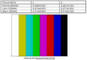
1. Use Konica Minolta
CS-200 for color coordinates and luminance check.
2. For suitable mass production at factory, colour analyzers CA-210 can be
applied. But, befor measureing ,all CA-210 should be
coordinates and proofread with a Charoma Meter (CS-200) or equivalent
instrument and a reference TV set.
|
3.
|
Check the luminance at
the center of the screen with 100% White. And to set Brightness control at
100; Contrast control at 100; backlight
control at 100.
|
|
Luminance
|
> 200 cd/m2 (Typ.)
[ For LC-19LE430E only at color temp.- *warm mode ]
> 200 cd/m2 (Typ.) [ For LC-22LE430E only at color temp.- *warm mode ]
|
>
400 cd/m2 (Typ.) [ For LC-26LE430E only at color temp.- cool mode ]
> 450 cd/m2 (Typ.) [ For LC-32LE430E only at color temp.- cool mode ]
> 450 cd/m2 (Typ.) [ For LC-37LE320E/RU/E(UK) only at color temp.- cool mode
]
> 450 cd/m2 (Typ.) [ For LC-42LE320E/RU/E(UK) only at color temp.- cool mode
]
4. The defult values of Scaler R Gain, Scaler G Gain, Scaler B Gain are all
128. When panel WD is made adjustment, the three values could not be over 128.
That is preventing color saturation after adjusting Contrast and Brightness
setting at main menu.
PC
mode display adjustment
1.
Display quality adjustment
Use timing mode as describe in 2.2, and use the POPO (pixel on pixel off)
pattern to adjust the clock until no stripe and adjust the phase until clear picture.(“Auto”
will be done every time switching to PC mode and mode change) Check all preset
7 modes.
2. Auto color for signal slicering (B)
2.1 General set-up
Equipment Requirements:
Konica Minolta CS-200 or Equivalent Color analyzer. Chroma 2250 or equivalent
PC signal generator.
Input requirements:
Input Signal Type:
PC VGA signal
1. 1024X7684/60Hz PC mode with ”5 white block” pattern. (see pattern-1) Input
Signal Strength: 0.7 Vp-p linear voltage.
Input Injection Point:
PC D-SUB input
Alignment
method:
Initial
Set-up:
1. Select source as “PC”.
2. Set Contrast = 58 (Sharp) and Brightness=100 (Sharp) , at normal menu mode.
3. Apply “5 white block”(pattern-1) pattern by VGA pattern generator.
4. Enter factory mode menu: press MENU + Numeric keys “1999” + press PRE PR
(factory mode menu).
Alignment:
At factory mode menu, select AUTO_COLOR item. Then press “OK” key to
adjust ADC-GAIN-R, ADC-GAIN-G, ADC-GAIN-B and
ADC-OFFSET-R, ADC-OFFSET-G, ADC-OFFSET-B. Then store those values to NVM.
Set Contrast = 100 (Sharp) and Brightness=100 (Sharp)
Check color temperature specification with PC mode.
Color temperature Normal/Warm/Cool (x, y) co-ordinates specification:
1. Use Konica Minolta
CS-200. for color coordinates and luminance check.
2. For suitable mass production at factory, colour analyzers CA-210 can be
applied. But, before measuring ,all CA-210 should be coordinates and proofread
with a Charoma Meter (CS-200) or equivalent instrument and a reference TV set.
3. Check the luminance in the center of the screen with 100% White. And to
Brightness control at 100; Contrast control at 100
|
Luminance
|
> 200 cd/m2 (Typ.)
[ For LC-19LE430E only at color temp.- *warm mode ]
> 200 cd/m2 (Typ.) [ For LC-22LE430E only at color temp.-*warm mode ]
|
>
400 cd/m2 (Typ.) [ For LC-26LE430E only at color temp.- cool mode ]
>450 cd/m2 (Typ.) [ For LC-32LE430E only at color temp.- cool mode ]
> 450 cd/m2 (Typ.) [ For LC-37LE320E/RU/E(UK) only at color temp.- cool mode
]
> 450 cd/m2 (Typ.) [ For LC-42LE320E/RU/E(UK) only at color temp.- cool mode
]
SERVICE MODE LC-19LE430E/UK, LC-22LE430E/UK, LC-26LE430E/UK, LC-32LE430E/UK
Press MENU + Numeric
keys “1999” + press PRE PR to enter factory mode.
SOFTWARE UPGRADE PROCEDURE
TROUBLESHOOTING TABLES
 SERVICE MODE


