BOOG DPS21K5 schematic
USED Ics: TL074, IRS2092, IRFBA90


ROCKFORD FOSGATE AUTO AMPLIFIER – 100+100 WATTS - SCHEMATIC
USED Ics: LM833SM, BUZ11[FET], TL494SM, IRF9540, IRF540H


BOOG DPS21K5 schematic
USED Ics: TL074, IRS2092, IRFBA90
ROCKFORD FOSGATE AUTO AMPLIFIER – 100+100 WATTS - SCHEMATIC
USED Ics: LM833SM, BUZ11[FET], TL494SM, IRF9540, IRF540H
Philips 32PFL3200 POWER SUPPLY (SMPS) Schematic diagram – 715G4831


Philips 42PFL3300 POWER SUPPLY (SMPS) Schematic diagram – 715G4922


715G3936 & 715G3967

Philips 39PFL5046 POWER SUPPLY (SMPS) Schematic diagram


TCL 50P65US SMPS SCHEMATIC

TCL 50P65US Backlight Schematic

TCL 50P65US-PSU connector 12Volt and connector 12Volt to 5Volt

TCL 50P65US-12VPSU TO 3.3V STB and 12V TO 1.5V CPU POWER

TCL 50P65US-5V TO 1.10V Core Power

TCL 50P65US-AD82587D – Audio Output Power schematic


MENU Upgrade
1. Rename the upgrade file
V8-T841T01-LF1V021.img into install.img
2. Put bin file to the root of the
Udisk, and plug in TV set through USB.
3. Go to factory menu
a) Press settings button under HDMI
source
b) Picture & Display->Picture
Adjustment-> Advanced Settings->Brightness->Contrast
c) press “1950” on Contrast
d) other->USB Update
4. Press Main update, it will power
off and upgrade in 10 Seconds you will see the upgrade process shown on the screen.
USB key Update
1. Put the Key file as below to the
USB root directory, and connect to TV, it will update the TV Key.
2. After update the keys,
it will display “OK” on screen
3. Done.

SMPS (Power supply board) schematic

Trouble shooting
No power LED, RC or Key cannot turn on TV. Power LED no light - no change.

Back light is OK, sound is OK, but no picture.

Power LED logic OK, sound OK, but no picture (Different from No Display).

One or All signal source without sound.

One or several source no function.

Abnormal Display. OSD NG or picture NG.

No tuning channels. DTV or ATV no Channels.

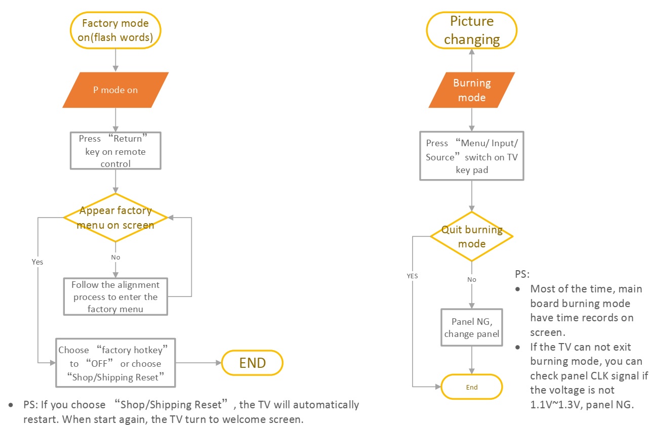
P mode on and burning mode
These chassis are designed for European LCD TV markets Ready for IPTV. The main chip is from novatek NT72563 series with embedded Linux core and supports below features matrix:

NT72563 D2900

NT72563 P6

Manufacturing Connectors Pin out
ISP-UART - P15 Pin1: NC. Pin2: RXD. Pin3: TXD. Pin4: GND.
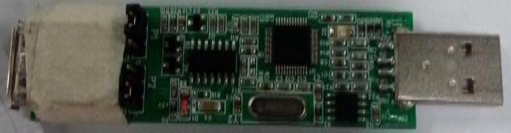
USB to UART Bridge Adapter (FT2232D chipset series)
To communicate with TV product for debugging, adjustment and so… it’s required suitable 0.5V Serial Interface like following snapshot (further details are described on below sections):
Test and Alignment Specification for NT63 Series (v0 01) 170612
All tests and measurements
mentioned hereafter have to be carried out at a normal mains voltage (220 ~ 240 VAC)
All voltages have to be measured with respect to ground, unless otherwise
stated
All final tests have to be done on a complete set including LCD panel in a room
with temperature of 25+/-7°C
The Picture Performance assessment such as White Balance (luminance and
colour temperature) has to be performed into subdued lighted room after at
least 45min of warm-up in order
to avoid any temperature drift influence (colorimetric vs. time)
PCB-SKD Assembly: Test & Alignment
Pre-Conditions
and DC/DC Check
Before
power-on, please check the board according to the relevant block diagram and
circuit diagram, and make sure that no serious issue or mistake can destroy the
board. For example, the output of DC/DC and LDO should not be shorted to
ground.
Supply a suited voltage and power-on, then check the voltage according to the
relevant block diagram, circuit diagram and voltage specification.
For example, check SoC voltage (3V3, 1V8, CORE_1V2, 5V, 5VSTB, etc.), DDR
voltage (DDR-1V5), audio amplifier voltage (12V), etc...
Measurements should fulfil specification within ±5% tolerances.

SW Image download
Download
the latest release SW from below FTP server:
Link: \\10.120.99.200\
Username:
Password:
Folder: \\10.120.99.200\Software-release\Debugging-TS-SW\Novtek\NT563
LR or PR step. ---Only test
In
case of starting from blanked flash / eMMC, it’s necessary to use “Blank
upgrade” to update the SW.
MP Step
In
case of starting from blanked flash, it’s necessary to write “ V8-N563T01-LF1VXXX _emmc_writer.bin” file
via factory copy in advance.
OAD Stream
To manage quicker mass
reflashing on predefined DVB Channel, some licensed IBL tools ('xxx2lli.exe',
'lli2dsm.exe',dsmmerge.exe …) from Intel byte Inc. might be necessary to create
appropriate DVB SSU image. Over some predefine settings such as repeated data
block insertion, null packets size, … that are controllable in configuration
file, here below are mandatory OUI entries structure to prepare DSM-CC carousel
image format:
|
export CUST_OAD_OUI |
0x001C50 |
OAD reflashing is managed within 4 steps operation: multiplex detection, DVB transfer, flashing and warm-start.
UART & IR Parser
To
use both UART and/or IR parser, TV has to be set in Factory mode with its USB
port well connected to suitable UART device or an IR emitter device correctly
facing up TV (see below “Product Assembly - section 2.0” how to activate
“Factory key”).
The UART parser engine is enabled by sending following command “0xE2” from host to TV within following
presets 115200/8/n/1.
Once initialized, “PS” caption
is toggle displayed on bottom left screen (“S” like Serial).
To communicate with TV depending on SIACP revision layout implementation, you
need to fulfil UART/IR commands protocol and format described on enclosed SIACP
requirements document.
Project ID Modification
There
are different IDs stored in the eMMC depending on different Panels settings and
Models features, but there’s only one key branching Project ID that includes
all. So, it’s not recommended to modify Panel ID with Hyper terminal as other
ID features may not change.
To modify Project ID, you need to go through “Factory menu -> Other
-> Project ID -> Project ID”,
then spin left or right with RCU “◄/►”
keys to chose suitable ID (Project name is dynamically refreshed).It is
necessary to press “OK” key for saving the setting.
“How to change Project ID with RCU”
See below is the Project ID table for reference:
Functional Test
Once
the boards (chassis, KB, IR, PSU…) and the panel are well interconnected, plug
all external generator devices to relevant below inputs/outputs using
respective test patterns format to check picture and sound quality:
Picture video formats can be changed by the factory according to their own standard.
AD Calibration Test
As
the A/D self-calibration mechanism is built-in Soc, there’s no any ADC to
perform.
DDC & EDID & T-Link Test
The
E-EDID data structures are according to VESA Enhanced EDID 1.3 (and
EIA/CEA-861B for HDMI). CEA Timing Extension structure has been extended to
support all 3D capable timings.
All HDMI structures have their own BIN profile which are part of main SW and
uploaded at power-on into soc chipset:
For EDID check, it’s needed to check whether the correct EDID is downloaded by
checking corresponding EDID NVM Checksum or read them out to check bit by bit
if it is in line with the released EDID bin file.
HDCP Test
For
HDCP compliancy, it’s needed to check whether the HDCP key has been well set by
connecting suitable generator.
CI+ Key Upgrade, Activation and Test
See “How to upgrade CI Key using USB”, “How to upgrade ESN Key using USB”, “How to upgrade HDCP key & HDCP2.0 key using USB”
LAN and WLAN Test (MAC address and Device or User ID codes)
Here
are some representative codes examples:
MAC Address Upgrade (IPv6)
MAC can be set using UART
commands described on enclosed SIACP requirements (rev. v3.9).
Writing MAC command <0xB3>,
Data length <6>, Data type
<HEXA> (see below command
example from above MAC code) <AA 0B
B3 5C 36 B8 A8 9D CC 36
78>
|
Device ID (DID) |
Purpose is to allow Other Newtork Download (OND) and further specific Services via dedicated abroad portal (UK tbc).4 At final, when TV may ask for portal connection, there’ll be Device ID matching control sent by host (TV client) to ensure total integrity.
For such, specific DID (40
bytes) needs to be paired and overwritten into memory for internal client
encryption.
All DID and MAC codes have to be download from portal local service via
suitable factory workstation LAN system.
Then during production lot, it’s necessary to send/write all those codes to
each TV.
DID codes can only be set using UART commands described above on enclosed SIACP
requirements (rev. v3.9).
Writing Device ID command <0xB2>, Data length <32>, Data type <ASCII> (see below command example
from above DID code)
<AA 25 B2 42 45 34 46 32
35 35 42 42 44 31 30 36 42 43 38 46 38 30 36 41 45 34 35 36 33 35 30 44 39 31
46 48 93>
|
LAN Test |
A
rough LAN test can be done by connecting DHCP server to TV’s RJ45 and check
that IP, subnet mask, DNS, …
addresses are visible on “Settingsà NetworkàInternet
connection(On)àIP settings”.
More in-depth test can be performed faster using suitable UART/IR commands
following SIACP requirements. SW will internally manage Network ID (NID) flag
controlling all MAC/DID/UID integrity to facilitate PA screening further.
It’s not necessary to check video and audio from DLNA server.
Factory Menu
Follow
the below steps to pop-up the Factory menu in case of “Factory hotkey” is disabled:
Press RCU “MENU” key to display Setting menu
Select Picture
Scroll down to “Contrast”
item
Press the subsequence RCU keys “9”, “7”, “3” and “5”
In case of “Factory hotkey” is enabled,
just press RCU “Return” key to pop-up again the Factory menu.
The status of “Factory Key” can
be changed in “Factory Menu->Hotkey”
Press RCU “OK/►” key to enter
the submenu.
Press RCU “Menu” key to go back
to the root menu.
Press RCU “◄/►” key to change
the values.
Press RCU “OK” key run the
function.
Press RCU “Exit” key exit the
Factory menu.
Factory Captions Description
While “Factory hotkey” is enabled, there’s some toggled display information
(~2s) relative to SW, Project ID, CI+, Network ID to facilitate 100% quick
screening without accessing to whatever else menu:
Main
SW Ver
Project ID (ID)
ERG(PVR)
CI Key Activation flag (CI+ key)
MID(Internet infor for factory)
P (Production/Factory mode flag) / S (Factory UART Parser mode flag) / W (Warm-Up
mode flag)

Warm-up Test
Following
TCL standard and practices, it’s required minimum 15min of Warm-Up that
can be considered as Burn-In.
Additional Aging for White Balance alignment is no more necessary due to
consistent Picture Performance with Cloning usage.
This function is accessible by selecting “Factory menu àWARM UP”, pressing RCU “OK/►”
key and then leaving Factory menu by pressing “Exit” key. To release/disable Burn-in mode, it’s just required to
press “Menu” button from local
keyboard. Other faster methods via UART/IR commands are available on enclosed
SIACP requirements (rev. v5.4).
White Balance Touch-Up (Golden sample)
As
some colour coordinates discrepancies can be noticed from panel batches to
others, it may necessary to perform slight touch-up.
For Colour temperature adjustment, switch TV on leading HDMI input where should be connected suitable generator providing
following format 1280x720p@60Hz test
pattern. A 32 steps grey scale is recommended to assess relevant calorimetric
tracking and low/high light saturation points.
Ensure that TV’s picture
enhance is off.
Ensure that TV is in Factory mode to access to ”White Balance” adjustment submenu, then scroll down to toggle off
“Pic. Enhance” flag.
WB Normal is the first mode which is adjusted in HDMI source, the next are HDMI warm and
cool mode.
Warm and Cool Tone are relatives to Normal
mode. WB adjust need to fix default G Gain .Offset registers needn’t to
be adjusted.
“Gain” registers set need to be
adjusted at 70IRE.
Targets and Tolerances for all inputs
(According to company uniform LED color temperature standard of panel)
The
measured and adjustable parameters should be mainly “x”, “y”
coordinates.
The White Balance alignment should be performed using a well calibrated and
contact less analyzer (ex: Minolta CA210 or CA310). The analyzer may not touch
the screen surface, and measurement must be performed in a dark environment
keeping the probe(s) at 90+/-2° from the panel centre.
The results should fulfil specification for each TV set offered by R&D and
below tolerances::
Important: If measurements are performed on whatever else LED panel with Minolta CA210, it’s required to calibrate additional channel (ex: CH01) using relative following offsets (CH00 remains for CCFL panel): +0.002 for “x” and +0.012 for “y”.
Cloning
Once
a TV is well aligned and prepared (channels maps, volume, picture presets…),
user can prepare golden clone image that can be copied on demand to all further
TV production lot of same TV. To access cloning function, you can select “Factory menu àUSB Clone && Update”, Scroll down to “TV to USB” or “USB to TV”
and press RCU “OK/►” key to
process. 4 BIN images will be created, overwritten or read on USB stick (pen
drive) depending on chosen template like following: “database\database\***.db”. These files need to be used strictly
with MT5655 SoC platform as depending on SW structure.
Other faster access methods via UART/IR commands are available on enclosed
SIACP requirements.
High Pot and Insulating Resistance Tests
At the end of the process, a “High Voltage” and an “Insulating Resistance”
tests are required to fulfil Safety Electrical requirements (CEI 65065).
High Voltage Withstanding requirements ▪ Insulating Resistance requirements
“Voltage” > 3500 VAC -
“Voltage” > 500 VDC
“Max Leakage Current” > 10 mA
- “Threshold Min” > 4M Ω
“Test Time” > 3 sec -
“Test Time” > 2 sec
SHOP-END Test
At
final process stage, it’s necessary to perform “Reset shop” before any packing to leave Factory mode and restore
User default presets.
This function is accessible by selecting “Factory menu - Reset Shop”, then pressing RCU “OK/►”
key. Other faster methods via UART/IR commands are available on enclosed SIACP
requirements.
A password might be required in case of Parental Control function is locked, use default “1234” password or “0423” super password to clean-up existing ones if forgotten.
“How to upgrade SW FLASH using Blank upgrade”
Download
boot bin “ tcl_m1v1_eu_secure_emmcboot.bin” & blank upgrade main
software“upgrade_loader.pkg” from the software website.
Connect UART interface to suitable manufacturing TV input connector, upgrade
boot bin first to blank IC.
1) copy
all files under the directory to the root directory of the u disk..
2) Serial
port with USB 3.0 port, USB flash disk to connect USB 2.0.
3)
Locate
the p901 port on the motherboard ( near the high frequency tuner ), short with
tweezers or other tools.
4)
Ac
on the AC, the following serial port shows that is in the air, tweezers and
other tools to remove, do not need to be short.

After finish update SW, TV
will reboot automatically and please remove USB key.
Remember to perform “Factory menu - Reset ALL“ and “Factory menuàReset Shop“, and then press RCU “OK/►”
key
“How to upgrade main software using USB”
Copy
the MAIN SW BIN image “V8-N563T01-LF1Vxxx.bin”
into USB stick (pen drive) root path.
Name “V8-N563T01-LF1Vxxx.bin” as
“update.zip”, please delete
other xxx.pkg files from USB stick.
(Make
sure the USB remaining available storage is more than 1GB)
Plug
USB stick to the TV.
Power on TV by AC, at the same time press “power on” key for 10s, TV will
update SW automatically.
When reflashing is successful, TV should restart automatically (about 4min).
Remember to perform “Factory menu - Reset ALL“ and “Factory menu - Reset Shop“, and then press RCU “OK/►”
key. Finally, restart the TV.
How to upgrade main SW using USB and RCU
Power on TV.
Copy the SW BIN image “V8-N563T01-LF1Vxxx.bin”
into USB stick (pen drive) root path.
Plug USB stick to the TV. Option-->settings--> Support--> Software
update -->By USB. TV will find Vxxx and
please do “update”.
TV will update SW automatically, and show some notes on TV.
When reflashing is successful, TV should restart automatically after ~4min.
Remember to perform “Factory menuàReset ALL“ and “Factory menuàReset Shop“ and then press RCU “OK/►”
key.
Switch off TV by removing AC cord. Reconnect AC cord to restart TV.
“How to change Project ID with RCU”
Process following subsequence IR codes to
change projectID: 062598+MENU+xxx (xxx:ProjectID,
ex: 001)
If it works, the TV will restart
automatically.
“How to upgrade CI+ Key using USB”
Create
a new folder named “CI+KEY” on
USB stick (pen driver) root path.
Copy corresponding “*.key” files
into CIKEY folder.
Under CIKEY folder, create a new folder named “backup” (once the CI key is overwritten, the matching key file will
be moved to this folder)
Plug USB stick to the TV
Go to “Factory menu - Other - Update
CI+ Credential - Update
From USB“ and then press RCU “OK/►”
key
The “Valid” flag should now be enabled (turns to “Yes”), “Custom Code” should
display “TCL” and “Serial Num.” field
should update with Key number.
Remove USB stick
Note: If unfortunately the process failed, you may need to download new
CI key and repeat operation again.
“How to upgrade Netflex ESN using USB”
Under
USB root path, create a new folder named as “esn”, then copy corresponding ESN KEY bin files into this folder;
Under “esn” path, the key should
be named as “nflxk_***”,like this ,
Plug USB stick to the TV;
Go to “Factory menu > Clone & Update > ESN Key Upgrade“ and then press RCU “OK”
key
Remove USB stick
If unfortunately the process failed, you may need to download new ESN key and repeat operation again.
“How to upgrade HDCP key & HDCP2.0 key using USB”
Copy
HDCP.bin, HDCP2.bin into USB stick (pen drive) root path, please pay attention
to the spell.
Picture ->contrast -> “1950” -> Main Menu
Go to “Main Menu > Service Menu > USB UPDATE > HDCP Upgrade (HDCP2.0 Upgrade)
“How to upgrade MAC Address using USB”
Go
to “Factory menu > Other > IPTV > Update MAC Address > Update From USB“,but there is no this function which is only displaying.
The “Written status” flag should now be enabled (turns to “Yes”) and “MAC
address” should display corresponding address like onto below snapshot:
“Network Connection Setup”
Note:
You can set up your TV so that it can access the Internet through your local
area network (LAN) using a wired or wireless connection.
▪ Wired Network Connection
You can connect your TV to your LAN using cable in three ways:
1) Plug your TV to your LAN by connecting the LAN port on your TV to an
external modem using a Cat5 cable.
2) Plug your TV to your LAN by connecting the LAN port on your TV to an IP
Sharer which is connected to an external modem. Use Cat5 cable for the
connection
3) Depending on how your network is configured, you may be able to plug your TV
to your LAN by connecting the LAN port on your TV directly to a network wall
outlet using a Cat5 cable (Note that the wall outlet is attached to a modem or router elsewhere in
your house)
Select “Option > Settings > Network - Internet connection (On) > Interface > Ethernet”, then select
“IP settings” to connect to
network.
Wireless Network Connection
To
connect your TV to your wireless network, you need a wireless router or modem
and a Wireless LAN Adapter.
Connect your “Wireless USB Adapter” (USB dongle) delivered with your TV to your
TV’s USB .
Select “Option > Settings > Network > Internet connection(On) > Interface”, then select “Wireless”
to connect to a wireless network
Select “Wireless settings” and
press “OK/►” to enter.
You can setup the wireless network connection three ways:
1) “Scan” mode
Select “Wireless settings > Scan”, then press “OK/►”, the TV will scan all available
access points and then display them.
Select an available access point, then press “OK/►” to connect the TV to it.
Note: If you select a
protected access point, you will have to enter the corresponding password.
Press “OK” on the remote
control to display virtual keyboard to enable you to enter the password.
2) “Manual” mode
Select “Wireless settings > Manual”, then press “OK/►”, you will be prompted to enter
the correct SSID of an available wireless router to setup the connection.
3) “Auto” mode
If your AP supports WPS (Wi-Fi Protected Setup), you can connect to the network
via PIN (Personal Identification Number) or PBC (Push Button Configuration).
WPS will automatically configure the SSID and WPA key in either mode.
Select “Wireless settings - Auto”, then press “OK/►”
to enter.
Network Setup
Press “Option” on the remote control and
select “Option - Settings - Network - Internet connection”. Then press “OK/►”
key to select “On”. Wait until
the connection is automatically established.
Select “Option - Settings - Network - Connection
test”,
then press “OK/►” to check the
Internet connectivity. If failed, follow below steps to ensure connectivity
Select “Option - Settings - Network - IP
settings”, then press “OK/►”
to enter into “IP settings”
submenu
Set “Address type” to “Auto” by pressing “OK/►” key, it will acquire and enter
the new detected IP address automatically.
You can also follow below steps to enter your IP address manually.
Set “Address type” to “Manual” by pressing “OK/►” key, then press “▼” key to go to
the first entry field.
Enter the “IP address”, “Subnet mask”, “Default gateway”, “Primary
DNS” and “Secondary DNS” values.
Use remote control digital keys to enter numbers and “◄/►” key to move from one
to other field location
After setting all required inputs, select “Option-->Setting - Network - Connection test” to check the Internet connectivity again
Select “Option > Settings > Network > Information”, then press “OK/►”
key to display current connection details, such as Interface, Address type, IP
address, etc..
“How to upgrade Flash SW using Network”
Please
follow Appendix (10), make sure your TV is connected on the internet.
Update through the menu
Select “Option > Settings > Support > Software update > By network”,
then TV starts to search new software automatically .If new software is
detected, the page will show the button and hint that can guide you.
Select “Download”, software will be downloaded automatically. The download progress will be shown in the lower right corner:
Please follow the
instructions on TV if download or update failed. And you can check your network
and try again.
Please wait for a moment, when the progress appears from 0% to 100%, TV will
show a dialog to ask you if you want to update.
You can select “Later” if you don’t want to update
now. While you select “Never”,
the dialog will not be shown until new software is detected.
Select “Update”, TV will update
automatically. First the following dialog will be shown. Then TV will restart automatically
to finish updating:
Please do NOT power off TV
until it restart successfully.
You can select “Option - Settings - Support - Software
update”, the “Current version” shows the new Software version.
Update through auto detection
When your TV has powered on and connected on the internet, a dialog will
appear on TV if TV detects new.
You can select “Later” if you don’t want to download
software and if you select the “Never”,
the dialog will not be shown until another new software is detected.
Select “Download” and TV will
download automatically;
All the following operation is same as “Update
through the menu”.
This circuitry measures the distance walked during a walk. The hardware is located in a small box placed in your pants pocket and the display is conceived as follows: The leftmost display D2 (the most significant digit) shows 0 to 9 km. and its point is always further to separate km. from hm. The rightmost display D1 (least significant digit) shows hundreds of meters and its point lights up after every 50 meters walk. The beeper (excluded) signals every unit count, repeating every two steps.
A normal step has been calculated to cover about 78 centimeters, so the LED signaling 50 meters lights up after 64 steps (or 32 mercury switch operations), the display shows 100 meters after 128 steps and so on. When the battery is low, the display lights up only when requested by pressing P2. Accidental resetting of the counters is ruled out because both buttons must work together to reset the circuit.
Obviously this is not a precision meter, but its degree of approximation has been found to be good for this type of device. In any case, the most important thing to do is to properly place the mercury switch inside the box and set its degree of tilt. IC1A and IC1B form a monostable multivibrator, providing some degree of freedom from excessive bounce of the mercury switch. Consequently, a pure square pulse is fed to IC2, which is divided by 64. Q2 controls the point segment of LED D1 every 32 pulses counted by IC2. Either IC3 and IC4 divide by 10 and control the displays.
P1 resets the counters and P2 turns on the displays. IC1C generates a rectangular audio frequency, which is switched on for a short time with each monostable count. Q1 turns on the piezo sounder and SW2 allows you to mute the beeper.


Main PWB: Vestel 17MB08, 17MB15
Service menu
To enter the service menu, first enter the MENU by pressing MENU button and then press the digit 4, 7, 2 and 5 respectively.
Picture adjust: source: all possible sources given with the chassis as list.
Mode: three items as a list; Natural, Dynamic, Cinema
Color temp: three items as a list; Cool, Normal, Warm.
Contrast: slider bar. Changing value between 0 and 63.
Brightness: slider bar. Changing value between 0 and 63.
Sharpness: slider bar. Changing value between 0 to 31.
Color: slider bar. Changing the value between 0 to 99.
R: slider bar. Changing the value between 0 to 31.
G: slider bar. Changing the value between 0 to 31.
B: slider bar. Changing the value between 0 to 31.
Backlight: slider bar. Changing the value between 0 to 255.
In this menu preset values for each mode (contrast, brightness, sharpness, color values for each mode NATURAL, DYNAMIC, CINEMA and for each color temp: R, G, B values for each color temp- COOL, NORMAL, WARM are determined for each source.
Block diagram

PCB layout


RESONANT MODE TFT POWER SUPPLY: 26, 32 and 37 inch Hitachi LCD TVs
