FUJITSU P42HCA30 - PLASMAVISION - ERROR MESSAGES - LED BLINKING CODES

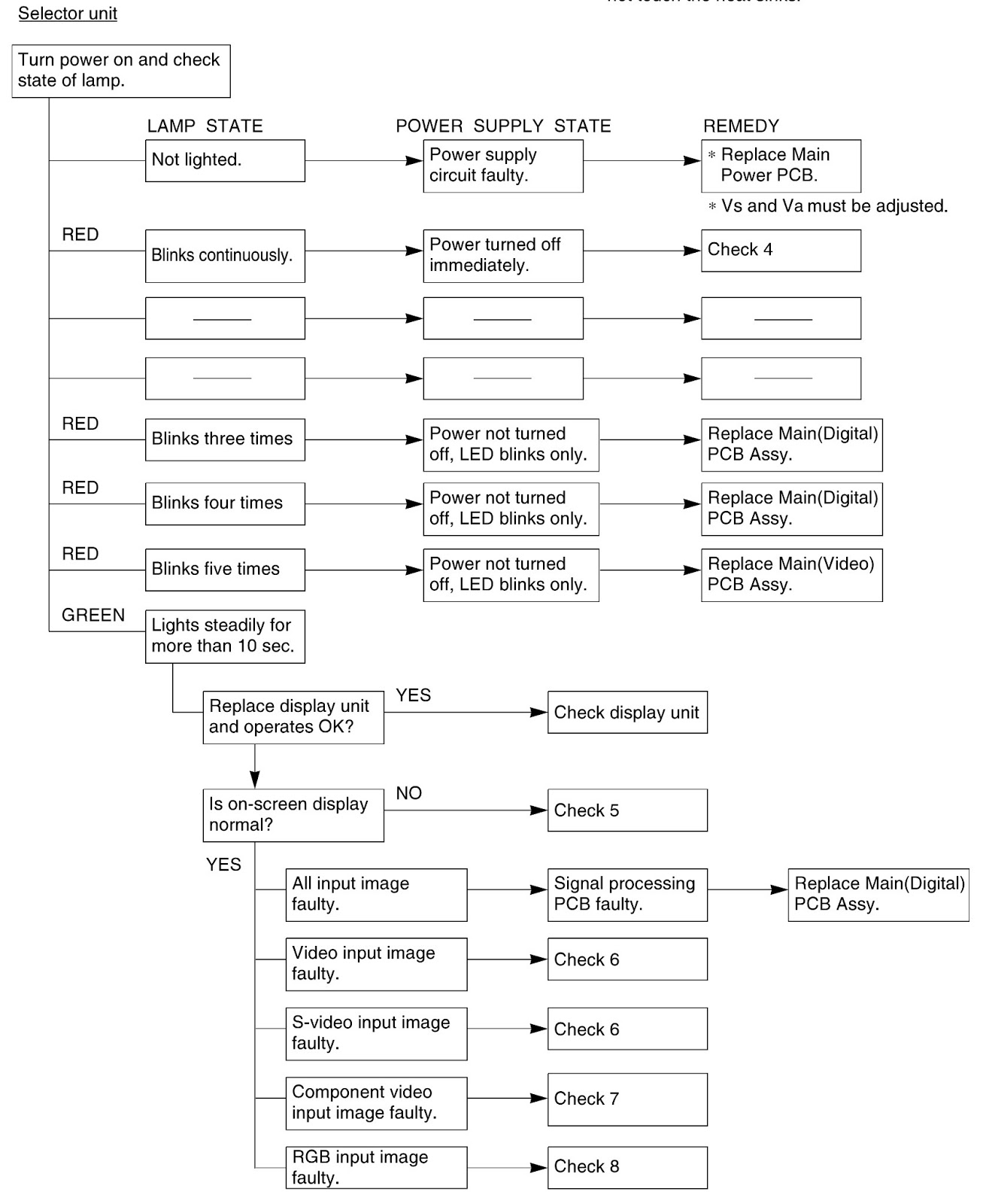
ERROR CODES
OSD
Three kinds of error messages are displayed on the screen,
and the power is turned off 10 sec later.
LED
LED error is displayed continuously after the power is
turned off.
OSD
On screen display
|
Cause
|
Check point
|
ERROR MESSAGE CONDITION 1
|
Fan protector operated
|
Fan
Main power PCB
Main/Digital PCB
|
ERROR MESSAGE CONDITION 2
|
Temperature protector
operated
|
Ambient temperature of unit
Main/Digital PCB
Temp. sensor IC6950
|
LED lamp display status
|
Cause
|
Check point
|
Steady light (Red)
|
Stand-by status
|
-----------------------
|
1 time (Red) / 1 time (Green)
Flashes once Red LED and flashes once Green LED every 3
sec.
|
No power. Power
supply protector operated
|
Main power PCB
|
1 time (Red) / 2 times (Green)
Flashes once Red LED and flashes twice Green LED every 4
sec.
|
No power. Power
supply protector operated
|
PDP panel
|
1 time (Red) / 3 times (Green)
Flashes once Red LED and flashes three Green LED every 5
sec.
|
No power. Power
supply protector operated.
|
Main/Digital PCB
|
2 times (Red) / 1 time (Green)
Flashes twice Red LED and flashes once Green LED every 4
sec.
|
Temperature protector
Operated
|
Ambient temperature of unit
|
2 times (Red) / 2 times (Green) Flashes twice Red LED and
flashes twice Green LED every 5 sec.
|
Temperature protector
operated
|
Main/Digital PCB
Temp. sensor IC6950
|
3 times (Red) / 2 times (Green) Flashes three Red LED and
flashes twice Green LED every 6 sec
|
EEPROM device fault
|
Main/Digital PCB
|
3 times (Red) / 3 times (Green) Flashes three Red LED and
flashes three Green LED every 7 sec
|
EEPROM device Read /
Write fault
|
Main/Digital PCB
|
4 times (Red) / 1 time (Green)
Flashes four Red LED and flashes once Green LED every 6
sec
|
Main/Digital circuit fault
|
Main/Digital PCB
|
5 times (Red) / 1 time (Green)
Flashes five Red LED and flashes once Green LED every 7
sec
|
Video circuit fault
|
Video PCB
|
6 times (Red) / 1 time (Green)
Flashes six Red LED and flashes once Green LED every 8 sec
|
Fan protector operated
|
Fan-1
Main/Digital PCB
|
6 times (Red) / 2 time (Green)
Flashes six Red LED and flashes twice Green LED every 10
sec
|
Fan protector operated
|
Fan-2
Main/Digital PCB
|