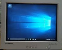
 15 inch and 17 inch Samsung CRT type computer monitors circuit
diagram and service adjustment procedure
15 inch and 17 inch Samsung CRT type computer monitors circuit
diagram and service adjustment procedure
15-Inch
(38 cm): 13.8-inch (35 cm) viewable, 17-Inch (43 cm): 16-inch (40.6 cm)
viewable, Full-square flat-face tube, 90˚ Deflection, Semi- tint, Non-glare,
Invar shadow mask, Anti-static silica coating, 0.28 mm Dot pitch.
15”
; Horizontal : 267 mm ± 4 mm, Vertical : 200.5 mm ± 4 mm
17”
; Horizontal : 306 mm ± 4 mm (4:3 ratio), Vertical : 230.5 mm ± 4 mm.
Alignment and Adjustments.
Caution:
Changes made without the Softjig are saved only to the user mode settings. As
such, the settings are not permanently stored and may be inadvertently deleted
by the user.
The
following equipment may be necessary for adjustment procedures:
Display control adjustment
1.
Non-metallic (Ð) screwdriver: 1.5, 2.5, 3 mm
2.
Non-metallic (+) screwdriver: 1.5, 2.5, 3 mm
3.
Digital Multimeter (DMM), or Digital Voltmeter
4.
Signal generator, or DM200 software
5.
Software: Softjig or DM200
6.
Interface Board Ver. 2.0 Code No. BH81-90001K
7.
Parallel communications cable (25-pin to 25-pin); Code No. BH81-90001H
8.
Signal cable (15-pin to 15-pin cable with additional 3-pin connector); Code No.
BH81-90001J
9.
5 V DC adapter, not supplied
10.
Personal computer
Note:
Softjig AssÕy (includes items 6, 7 and 9)
Code
No. BH81-90001L.
colour adjustments
1.
All equipment listed in (a), above
2.
Color analyzer, or any luminance measurement equipment.
Connecting
the SoftJig
Connect
the monitor to the signal generator and or PC as illustrated in Figures 4-1 and
4-2.
Note:
The signal cable connector which includes the 3-wire cable must connect to the monitor.
If you use Setup 2 (PC only, no signal generator) you can only make adjustments
to the signal timing available on that computer system. To make corrections to
all factory timings requires the use of an additional signal generator.
High voltage adjustment
Signal:
1024 x 768 (68 kHz/85 Hz) (17”)
800
x 600 (54 kHz/85 Hz) (15”)
Display
image: Don” care
Contrast:
Minimum
Brightness:
Minimum
Limit:
26.5 kV ± 0.2 kV (17”)
25
kV ± 0.2 kV (15”)
exception)
26.0 kV ± 0.2 kV for 17” SDD CRT that the DY type is DMX-1791AT
Measure
the hight voltage level at the anode cap.
High
voltage should be within the limit as above.
If
the high voltage needs adjustment use the following procedure.
Turn
the power off and disconnect the AC line cord from the power source.
2.
Turn the power on after connecting high voltage Probe.
3.
Using the jig, adjust the high voltage to the specification.
*
High Voltage Adjustment PROCEDURE using Softjig
1
Select matching model name in “Model” field.
2
Select “ @7: Zero Beam” in menu after selecting “Extra 1”
3
Adjust high voltage using control bar after selecting “HV MIN”
4
Turn the power off/on after adjustment finished.
5
Check the high voltage has been fixed with adjusted value after reselecting
“@7: Zero Beam”
Screen voltage adjustment
Signal:
1024 x 768 (68 kHz/85 Hz) (17”)
800
x 600 (54 kHz/85 Hz) (15”)
Display
image: Don’t care
Contrast:
Minimum
Brightness:
Minimum
Limit:
26.5 kV ± 0.2 kV (17”) 25 kV ± 0.2 kV (15”)
Screen
Voltage adjustment procedure using softjig is all the same as 4-2-1 but
selecting “G2 CONT” on the contrary to “HV MIN”
Centre raster
Adjust
SW401 so that the back raster comes to the centre when you apply each basic
mode for 15” and 17”
Cantering
Cantering
means to position the centre point of the display in the middle of the display
area.
Horizontal
size and position and vertical size and position control the cantering of the
display.
Adjust
the horizontal size and vertical size to their optimal settings: 306 mm (H) x
230 mm (V) for 17”, 267 mm (H) x 200 mm (V) for 15”.
Adjust
the horizontal position and vertical position to ² 4.0 mm of the centre point
of the screen.
*
In Softjig window, “Geometry” has to be selected for GD adjustment.
Horizontal size adjustment
Scanning
frequency: 68 kHz/85 Hz (17”) 54 kHz/85 Hz (15”)
Display
image: Crosshatch pattern
Brightness:
Maximum
Contrast:
Maximum.
Use
control bar after selecting “H-SIZE” in left menu to adjust the horizontal size
of the display pattern to 306 mm (17”) and 267 mm (15”). (Tolerance: ± 3 mm.)
If
“H-SIZE” is not enough to adjust it, select “SIZE B+” by turns.
Vertical size adjustment
Conditions
Scanning
frequency: 68 kHz/85 Hz (17”) 54 kHz/85 Hz (15”)
Display
image: Crosshatch pattern
Brightness:
Maximum
Contrast:
Maximum.
Use
control bar after selecting “V-SIZE” in left menu to adjust the vertical size
of the display pattern to 230 mm (17”) and 200 mm (15”). (Tolerance: ± 3 mm.)
Horizontal position adjustment
Scanning
frequency: 68 kHz/85 Hz (17”) 54 kHz/85 Hz (15”)
Display
image: Crosshatch pattern
Use
control bar after selecting “H-POSITION” in left menu to centre the horizontal
image on the raster.
Vertical position adjustment
Scanning
frequency: 68 kHz/85 Hz (17”) 54 kHz/85 Hz (15”)
Display
image: Crosshatch pattern
Use
control bar after selecting “V-POSITION” in left menu to center the vertical
image on the raster.
Linearity
Linearity
affects the symmetry of images as they appear on the screen. Unless each row or
column of blocks in a crosshatch pattern is of equal size, or within the tolerances
shown in Tables an image appears
distorted, elongated or squashed.
Horizontal linearity adjustment
Scanning
frequency: 68 kHz/85 Hz (17 “) 54 kHz/85 Hz (15”)
Display
image: Crosshatch pattern
Brightness:
Maximum
Contrast:
Maximum
To
adjust the Horizontal Linearity, refer to Tables for the tolerance range.
Increase
or decrease H-LIN to optimize the image.
Vertical linearity adjustment
Scanning
frequency: 68 kHz/85 Hz (17”) 54 kHz/85 Hz (15”)
Display
image: Crosshatch pattern
Brightness:
Maximum
Contrast:
Maximum
To
adjust the Vertical Linearity, refer to Tables for the tolerance range.
Use
control bar after selecting “V-LINEARITY BAL” in left menu to optimize the
image.
Trapezoid Adjustment
Scanning
frequency: 68 kHz/85 Hz (17”) 54 kHz/85 Hz (15”)
Display
image: Crosshatch pattern
Brightness:
Maximum
Contrast:
Maximum
Use
control bar after selecting “TRAPEZOID” in left menu to make the image area
rectangular.
Pin balance Adjustment
Scanning
frequency: 68 kHz/85 Hz (17”) 54 kHz/85 Hz (15”)
Display
image: Crosshatch pattern
Brightness:
Maximum
Contrast:
Maximum.
Use
control bar after selecting ‘PINBALANCE “ in left menu to optimize the image.
Parallelogram Adjustment
Scanning
Frequency: 68 kHz/85 Hz (17 “) 54 kHz/85 Hz (15”)
Display
image: Crosshatch pattern
Brightness:
Maximum
Contrast:
Maximum
Use
control bar after selecting “PARALLEL” in left menu to make the image area
rectangular.
Side Pincushion Adjustment
Scanning
frequency: 68 kHz/85 Hz (17”) 54 kHz/85 Hz (15”)
Display
image: Crosshatch pattern
Use
control bar after selecting “PINCUSHION” in left menu to straighten the sides
of the image area.
Tilt Adjustment
Scanning
Frequency: 68 kHz/85 Hz (17”) 54 kHz/85 Hz (15”)
Display
image: Crosshatch pattern
Brightness:
Maximum
Contrast:
Maximum
Use
control bar after selecting “ROTATION” in left menu to correct the tilt of the
display.
Degauss
No
adjustments are available for the degaussing circuit. The degaussing circuit
can effectively function only once per 30 minutes.
To Delete the User Mode Data
To
delete the adjustment data from the user modes, click “@4: USER DELETE” in
right meant.
Save the Data
To
save the adjustment data for a mode, press “@3: ALL MODE SAVE” in right meant.
Colour Adjustments
CAUTION:
Check below condition before colour adjustment
Video
signal : Analog 0.7 Vp-p (at 75 Ω)
Sync
: TTL level (H, V seperate signal)
*
Select “Colour” in Softjig menu for colour adjustment.
Colour Coordinates (Temperature)
Colour
temperature is a measurement of the radiant energy transmitted by a colour. For
computer monitors, the colour temperature refers to the radiant energy
transmitted by white. Colour coordinates are the X and Y coordinates on the chromaticity
diagram of wavelengths for the visible spectrum.
Measurement
instrument: Colour analyser
Scanning
frequency: 68 kHz/85 Hz (17”) 54 kHz/85 Hz (15”)
Display
image: White flat field at centre of display area
Luminance:
Maximum
Procedure
Use
the directions in sections 4-3-2 through 4-3-3 to adjust the color coordinates
for:
9300K
to x = 0.283 ± 0.02, y = 0.298 ± 0.02
6500K
to x = 0.313 ± 0.02, y = 0.329 ± 0.02
Colour
Adjustments for 9300K
4-3-2 (a) back raster colour adjustment
Scanning
frequency: 68 kHz/85 Hz (17”) 54 kHz/85 Hz (15”)
Display
image: Back raster pattern
Brightness:
Maximum
Contrast:
Maximum
Select
“@1: CHANNEL 1” in right menu to control the colour for 9300K.
2.
Adjust the luminance of the back raster to between 0.5 to 0.7 ft-L using control
bar after selecting “GREEN CUTOFF” in the menu.
3.
Use control bar after selecting “BLUE CUTOFF” in left menu to set the “y” coordinate
to 0.298 ± 0.02.
4.
Use control bar after selecting “RED CUTOFF” in left menu to 0.283 ± 0.02.
*
If colour values would not be matched desirable values, repeat sequence 3 and 4
after readjusting “GREEN CUTOFF” control a little different.
White balance adjustment
Scanning
frequency: 68 kHz/85 Hz (17”) 54 kHz/85 Hz (15”)
Display
image: White box pattern
Brightness:
0.06ft-L at Back Raster
Pattern
Display
Contrast:
Maximum
Use
control bar after selecting “RED GAIN”, “GREEN GAIN” and “BLUE GAIN” to adjust the
luminance to 45 ft-L (15”) and 46 ft-L (17”) with the color coordinates ranged
for
9300K
to x = 0.283 ± 0.02, y = 0.298 ± 0.02.
exception)
17” SDD CRT type-named (*/S-2) : 42ft-L.
ABL adjustment
Scanning
frequency: 68 kHz/85 Hz (17”) 54 kHz/85 Hz (15”)
Display
image: Full white pattern
Brightness:
Maximum
Contrast:
Maximum
Check
the ABL. If it is not within the Specifications, use the ABL controls to adjust
it. (15”: 33 ± 1 ft-L, 17”: 36 ± 1 ft-L )
2.
Select “@4: COLOR SAVE” to save the data.
3.
Select “@6: ALL COLOR SAVE” to save the CH2.
White balance adjustment verification
Scanning
frequency: 68 kHz/85 Hz (17”) 54 kHz/85 Hz (15”)
Display
image: Back raster pattern Full White Pattern
X-Y
Coordinates: x = 0.283 ± 0.02,
y
= 0.298 ± 0.02
ABL
Luminance Refer to 4-3-2(c)
Brightness:
Maximum
Contrast:
5 ft-L, 24 ft-L
Check
whether the colour coordinates of the back raster satisfy the above spec.
If
they do not, return to 4-3-2 (a) and readjust all settings.
2.
Display a full white pattern.
3.
Select “Geometry” in softjig menu.
4.
Select “@7: 5-ft “ in right menu.
5.
Check whether the white coordinates of the video meet the above coordinates
spec.
6.
Select “@8: 24-ft “ in right menu.
7.
Check whether the white coordinates of the video satisfies the above spec.
If
they do not, return to 4-3-2 (a) and readjust all settings.
Select
“Colour” and click “@2: CHANNEL 2” for colour adjustment for 6500K
Repeat
the sequence of 9300K adjustment.
The
luminance values the same as 9300K, but the colour coordinated of back raster
and white box are : x = 0.313 ± 0.02 y = 0.329 ± 0.02.
Luminance Uniformity Check
Luminance
is considered uniform only if the ratio of lowest to highest brightness areas
on the screen is not less than 7.5:10.
Scanning
frequency: 68 kHz/85 Hz (17”) 54 kHz/85 Hz (15”)
(1024
x 768)
Display
image: White flat field
Brightness:
Cut off point at 24 ft-L
Contrast:
Maximum.
Measure
luminance at nine points on the display screen (see figure below).
Focus Adjustment
Scanning
frequency: 68 kHz/85 Hz (17”)
54
kHz/85 Hz (15”)
(1024
x 768)
Display
image: “H” character pattern
Brightness:
Cut off point
Contrast:
Maximum
1.
Adjust the Focus VR on the FBT to display the sharpest image possible.
2.
Use Locktite to seal the Focus VR in position.
Colour Purity Adjustment
Colour
purity is the absence of undesired colour.
Conspicuous
misleading (unexpected colour in a uniform field) within the display area shall
not be visible at a distance of 50 cm from the CRT surface.
Orientation:
Monitor facing east
Scanning
frequency: 68 kHz/85 Hz (17”) 54 kHz/85 Hz (15”)
Display
image: White flat field
Luminance:
Cut off point at the centre of the display area.
Note: Color purity adjustments
should only be attempted by qualified personnel.
Use
the following procedure to correct minor colon purity problems:
1.
Make sure the display is not affected by external magnetic fields.
2.
Very carefully break the glue seal between the 2-pole purity convergence
magnets (PCM), the band and the spacer (see Figure).
3.
Make sure the spacing between the PCM assembly and the CRT stem is 29 mm ± 1
mm.
4.
Display a green pattern over the entire display area.
5.
Adjust the purity magnet rings on the PCM assembly to display a pure green
pattern.
(Optimum
setting: x = 0.295 ± 0.015, y = 0.594 ± 0.015)
6.
Repeat steps 4 and 5 using a red pattern and then again, using a blue pattern.
7.
When you have the PCMs properly adjusted, carefully glue them together to
prevent their movement during shipping.
Notes: 1. If a picture
does not appear, fully rotate the brightness and contrast controls clockwise
and re inspect.
2.
Check the following circuits.
•
No raster appears: Power circuit, Horizontal output circuit.
•
High voltage develops but no raster appears: Video output circuits.
•
High voltage does not develop: Horizontal output circuits.
Wiring
diagram
SMPS (Power regulator) schematic

 Video
Controller Part.
Video
Controller Part.


