REPAIRING AND NOT THROWING AWAY

Richtige Fernseher haben Röhren!

Richtige Fernseher haben Röhren!

In Brief: On this site you will find pictures and technical information about Service Modes, Circuit Diagrams, Firmware Update procedure, Disassemble procedure, Universal remote control set-up codes, Troubleshooting and more....

If you go into the profession, you will obtain or have access to a variety of tech tips databases HERE IT IS Master Electronics Repair !.

These are an excellent investment where the saying: 'time-is-money' rules. However, to learn, you need to develop a general troubleshooting approach - a logical, methodical, method of narrowing down the problem. A tech tip database might suggest: 'Replace C536' for a particular symptom. This is good advice for a specific problem on one model. However, what you really want to understand is why C536 was the cause and how to pinpoint the culprit in general even if you don't have a service manual or schematic and your tech tip database doesn't have an entry for your sick TV or VCR.

While schematics are nice, you won't always have them or be able to justify the purchase for a one-of repair. Therefore, in many cases, some reverse engineering will be necessary. The time will be well spent since even if you don't see another instance of the same model in your entire lifetime, you will have learned something in the process that can be applied to other equipment problems.
As always, when you get stuck, checking out a tech-tips database may quickly identify your problem and solution.In that case, you can greatly simplify your troubleshooting or at least confirm a diagnosis before ordering parts.

Happy repairing!
Today, the West is headed for the abyss. For the ultimate fate of our disposable society is for that society itself to be disposed of. And this will happen sooner, rather than later.

How to use the site:

- If you landed here via any Search Engine, you will get what you searched for and you can search more using the search this blog feature provided by Google. You can visit more posts scrolling the left blog archive of all posts of the month/year,
or you can click on the main photo-page to start from the main page. Doing so it starts from the most recent post to the older post simple clicking on the Older Post button on the bottom of each page after reading , post after post.

You can even visit all posts, time to time, when reaching the bottom end of each page and click on the Older Post button.

- If you arrived here at the main page via bookmark you can visit all the site scrolling the left blog archive of all posts of the month/year pointing were you want , or more simple You can even visit all blog posts, from newer to older, clicking at the end of each bottom page on the Older Post button.
So you can see all the blog/site content surfing all pages in it.

- The search this blog feature provided by Google is a real search engine. If you're pointing particular things it will search IT for you; or you can place a brand name in the search query at your choice and visit all results page by page. It's useful since the content of the site is very large.

Note that if you don't find what you searched for, try it after a period of time; the site is a never ending job !

..............The bitterness of poor quality is remembered long after the sweetness of todays funny gadgets low price has faded from memory........ . . . . . .....
Don't forget the past, the end of the world is upon us! Pretty soon it will all turn to dust!

©2010, 2011, 2012, 2013, 2014 Frank Sharp - You do not have permission to copy photos and words from this blog, and any content may be never used it for auctions or commercial purposes, however feel free to post anything you see here with a courtesy link back, btw a link to the original post here , is mandatory.
All posts are presented here for informative, historical and educative purposes as applicable within fair use. NOTHING HERE IS FOR SALE !

Showing posts with label ORION. Show all posts

Wednesday, 11 December 2019

ORION 22LB820H, CMK162A, CEK626A, CEK627A, LCD TVS – SERVICE MODE, SMPS SCHEMATIC, TROUBLESHOOTING


Multi Brands - Generic TV Chassis – How to enter the service mode, audio and power section schematics
HOTEL MODE FUNCTION
To set the Hotel mode, please follow the steps below.
1. Press the MENU > 1111 button on the remote control.
2. Press the DOWN button on the remote control, select the Hotel Mode. Then press the ENTER button.
3. The Hotel mode setting menu will appear.
4. Using the UP/DOWN button on the remote control, select the desired mode. Then press the ENTER button.
5. Using the LEFT/RIGHT button on the remote control, set the mode to desired setting.
6. The Hotel mode has now been set up.
To reset the Hotel mode, please follow the steps below.
1. Press the MENU > 1111 button on the remote control.
2. Press the DOWN button on the remote control, select the Hotel Mode. Then press the ENTER button.
3. The Hotel mode setting menu will appear.
4. Using the UP/DOWN button on the remote control, select the RESET.
5. Using the LEFT/RIGHT button on the remote control, please select "OK".
Then press the ENTER button.
6. The setting items has now been returned to initial value.
1) Even if setting it to "No Respond", the service mode function are effective.
2) If setting it to "OFF", it start up in same input source when you turn off the power before.
SERVICE MODE
Do not feel after other MENU
Check of the SUM DATA and MICON VERSION on the screen.
1: Press the MENU > 1111 button on the remote control to select "Version Info".
2: Press the ENTER button on the remote control.
3: After the confirmation of each check sum. Turn off power.
Wiring diagram
Troubleshooting guide

Audio schematic
Audio switch schematic
SMPS [Power] schematic


LED driver schematic

Friday, 5 April 2019

ORION TV29LB929 – 29 INCH LCD/LED TV – HOW TO ENTER SERVICE MODE, ADJUSTMENTS, SMPS AND BACKLIGHT INVERTER SCHEMATIC

Orion TV29LB929 – 29 inch LCD/LED TV – how to enter service mode, adjustments, SMPS and backlight inverter schematic

Power supply and back-light inverter circuit diagram, service mode, Hotel mode, Reset, white balance adjustment – Orion TV29LB929 LED LCD TV - Used ICs in power and back-light inverter section circuit => MIP2M40MSSCF, FA5640N-C6-TE3, FMV09N90E(SMPS Switching FET), BD8779EFV-E2 (Backlight voltage control) 
HOTEL MODE FUNCTION
To set the Hotel mode, please follow the steps below.
1. Press the MENU ---> 1147 button on the remote control
2. Press the DOWN button on the remote control
3. Select the "Setup" menu , then press ENTER button
4. Select the "Hotel Mode" menu, Select "On".
5. The Hotel mode setting menu will appear
6. Using the UP/DOWN button on the remote control, select the desired mode. Then press the ENTER button.
7. Using the LEFT/RIGHT button on the remote control, set the mode to desired setting.
8. The Hotel mode has now been set up.
To reset the Hotel mode, follow the steps below.
1. Press the MENU => 1147 button on the remote control.
2. Press the DOWN button on the remote control,
3. Select the "Setup" menu , then press ENTER button.
4. Select the "Hotel Mode" menu, Select "On".
5. The Hotel mode setting menu will appear.
6. Press the DOWN button on the remote control,
7. Select the Clear Lock menu "Clear Lock" menu then press ENTER button , then press ENTER button.
8. The setting items has now been returned to initial value
CHECK FOR THE FIRMWARE VERSION
This unit is provided with the following SERVICE MODES so you can repair, examine and adjust easily
Do not adjust after other items except "Version Info".
1. Check of the VERSION and SUM DATA on the screen.
1 : Press the MENU è 1147 button on the remote control.
2 : Press the DOWN button on the remote control,
3 : Select the "Setup" menu , then press ENTER button.
4 : Select the "Version Info" menu, then press ENTER button.
5 : On the screen as shown in Fig:
ADJUSTMENT PROCEDURE
On-Screen Display Adjustment
1. Press the MENU => 1147 button on the remote control.
2. Press the DOWN button on the remote control
3. Select the "Video" menu, then press ENTER button on the remote control.
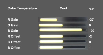
4. Select the "Color Temperature" menu , then press ENTER button on the remote control.
5. On the screen as shown in Fig:
PRINTED CIRCUIT BOARDS POWER (INSERTED PARTS)

SOLDER SIDE and POWER (CHIP MOUNTED PARTS)
SOLDER SIDE

SMPS and Back-light inverter board circuit diagram
WHITE BALANCE adjustments.
1. Place the set in Aging Test for more than 15 minutes.
2. Please select input About mode to adjust W/B.
3. Receive the gray scale pattern from the Pattern Generator.
4. Press the INPUT SELECT button on the remote control to set to the AV mode
5. Using the remote control, set the brightness and contrast to normal position.
6. Press the MENU è 1147 button on the remote control.
7. Press the DOWN button on the remote control.
8. Select the "Video" menu, and then press ENTER button on the remote control
ENTER button on the remote control ENTER button on the remote control.
10. Press the UP/DOWN button on the remote control to select the "R Gain", "G Gain", "B Gain", "R Offset", "G Offset", "B Offset
11. Adjust the LEFT/RIGHT button on the remote control to whiten the R Gain, G Gain, B Gain, R Offset, G Offset B Offset at each step tone sections equally..
12. Perform the above adjustments 10 and 11 until the white color is achieved.

Monday, 25 March 2019

ORION _ BUSH _ GRUNDIG _ MATSUI _ DECCA _ TATUNG - TVs _ CHASSIS PRO 4400 _ SERVICE INFORMATION & SCHEMATIC DIAGRAM

ORION _ BUSH _ GRUNDIG _ MATSUI _ DECCA _ TATUNG - TVs _ CHASSIS PRO 4400 _ SERVICE INFORMATION & SCHEMATIC DIAGRAM


BUSH 3463NTX_3472NTX_WS6667_WS7667_WST_66
ORION 3850_TV2844W_TV4400NTX
GRUNDIG T70-1020 _ WF82-3020
MATSUI 28N03 _ 32WN03
DECCA / TATUNG D28N440_D28W440_D28W441_T21N421_T25N440_T28N440_T32W440_T32W441S


Click on image.


ORION TV- 42007 S1 _ 42" PLASMA TV _ SERVICE MODE & ADJUSTMENTS AFTER MEMORY IC REPLACEMENT

ORION TV- 42007 S1 _ 42" PLASMA TV _ SERVICE MODE & ADJUSTMENTS AFTER MEMORY IC REPLACEMENT


SERVICE MODE OPTIONS

This unit is provided with the following SERVICE MODES so you can repair, examine and adjust easily.
To enter to the SERVICE MODE function, press and hold both buttons simultaneously on the main unit and on the remote control for more than the standard time in the appropriate condition.

SERVICE MODE LIST

Set Condition
Set Key
Remocon Key
Standard Time
Operations


TV mode


VOL. DOWN
(Minimum)


0


2 sec.
Reset the user setting items (PICTURE, VOLUME, LANGUAGE
and NICAM AUTO/OFF) to the initial state for delivery.


TV mode


VOL. DOWN
(Minimum)


1


2 sec
Initialization of factory TV data.
NOTE: If you set factory initialization, the memories are reset such as the channel setting, and the POWER ON total hours.


TV mode

 VOL. DOWN
(Minimum)

6

2 sec
POWER ON total hours are displayed on the screen.

Can be checked of the INITIAL DATA of MEMORY IC.


TV mode


VOL. DOWN
(Minimum)


9


2 sec
Display of the Adjustment MENU on the screen.
Refer to the "ELECTRICAL ADJUSTMENT" (On-Screen Display
Adjustment).

CONFIRMATION OF HOURS USED
POWER ON total hours can be checked on the screen. Total hours are displayed in 16 system of notation.
If you set a factory initialization, the total hours is reset to "0".
  • Turn on the POWER, and set to the TV mode.
  • Set the VOLUME to minimum.
  • Press both VOL. DOWN button on the set and Channel button (6) on the remote control for more than 2 seconds.
  • After the confirmation of using hours, turn off the power.
  1. OEC7128A_074  à MICON Version
  2. INIT 0001 80  à  Initial setting content of MEMORY IC.
  3. PDP ON 0010  à  POWER ON total hours.  =  (16 x 16 x 16 x thousands digit value) + (16 x 16 x hundreds digit value) + (16 x tens digit value) + (ones digit value).
WHEN REPLACING MEMORY IC
  • Turn on the POWER, and set to the TV mode.
  • Enter DATA SET mode by setting VOLUME to minimum.
  • Press both VOL. DOWN button on the set and Channel button (6) on the remote control for more than 2 seconds.

ADDRESS and DATA should appear.
===================================
OEC7128A_074
INIT 0001 80
PDP ON 0010
===================================
  • ADDRESS is now selected and should "blink". Using the RIGHT/LEFT button on the remote, step through the ADDRESS until required ADDRESS to be changed is reached.
  • Press ENTER to select DATA. When DATA is selected, it will "blink".
  • Again, step through the DATA using RIGHT/LEFT button until required DATA value has been selected.
  • Pressing ENTER will take you back to ADDRESS for further selection if necessary.
  • Repeat steps 4 to 7 until all data has been checked.
  • When satisfied correct DATA has been entered, turn POWER off (return to STANDBY MODE) to finish DATA input.
  • After the data input, set to the initializing of shipping.
  • Turn on the POWER, and set to the TV mode.
  • Press both VOL. DOWN button on the set and Channel button (1) on the remote control for more than 2 seconds.
  • After the finishing of the initializing of shipping, the unit will turn off automatically.  The unit will now have the correct DATA for the new MEMORY IC.

ORION TV- 42007 S1 _ 42" PLASMA TV _ ELECTRICAL ADJUSTMENTS

ORION TV- 42007 S1 _ 42" PLASMA TV _ ELECTRICAL ADJUSTMENTS


ADJUSTMENT PROCEDURE

Read and perform these adjustments when repairing the circuits or replacing electrical parts or PCB assemblies.
Use an isolation transformer when performing any service on this chassis.
When removing a PCB or related component, after unfastening or changing a wire, be sure to put the wire back in its original position.
When you exchange IC and Transistor with a heat sink, apply silicon grease (YG6260M) on the contact section of the heat sink. Before applying new silicon grease, remove all the old silicon grease. (Old grease may cause damage to the IC and Transistor).

BASIC ADJUSTMENTS:  ON-SCREEN DISPLAY ADJUSTMENTS
  • Set the VOLUME to minimum.
  • Press the VOL. DOWN button on the set and the channel button (9) on the remote control for more than 2 seconds to display adjustment mode on the screen.
  • Use the Channel UP/DOWN button or Channel button (0-9) on the remote control to select the options.
  • Press the MENU button on the remote control to end the adjustments.
  • To display the adjustment screen for AV mode, press the 0/AV button on the remote control to set to the AV mode. Press the VOL.DOWN button on the set and the channel (9) on the remote control for more than 2 seconds.
ADJUSTMENT ITEMS

H POSI OSD
V POSI OSD
R DRIVE (N)
R CUT OFF (N)
G DRIVE (N)
G CUT OFF (N)
B DRIVE (N)
B CUT OFF (N)
R DRIVE (C)
R CUT OFF (C)
G DRIVE (C)
G CUT OFF (C)
B DRIVE (C)
B CUT OFF (C)
R DRIVE (W)
R CUT OFF (W)
G DRIVE (W)
G CUT OFF (W)
B DRIVE (W)
B CUT OFF (W)
H POSI 50Hz
H POSI 60Hz
V POSI 50Hz
V POSI 60Hz
BRIGHT CENT
BRIGHT MAX
BRIGHT MIN
TINT
SHARP CENTER
SHARP MAX
SHARP MIN
CONTRAST CENTER
CONTRAST MAX
CONTRAST MIN
COLOR CENT
COLOR MAX
COLOR MIN
H POSI TEXT
V POSI TEXT
NT COLOR CENT
NT COLOR MAX
NT COLOR MIN
RGB BRIGHT CENT
RGB BRIGHT MAX
RGB BRIGHT MIN
RGB CONTRAT CENT
RGB CONTRAT MAX
RGB CONTRAT MIN
RGB COLOR CENT
RGB COLOR MAX
RGB COLOR MIN
RGB SHARP CENT
RGB SHARP MAX
RGB SHARP MIN
RGB V POSI 50Hz
RGB V POSI 60Hz
RGB H POSI 50Hz
RGB H POSI 60Hz
INVERSION
CONT CENTER
  1. Receive the Window Pattern .(RF Input)
  2. Activate the adjustment mode display and press the channel button (35) on the remote control to select "CONTRAST CENTER".
  3. Check if the step No. CONT CENT is "140".
  4. Receive a broadcast and check if the picture is normal.
  5. Press the 0/AV button on the remote control to set to the AV/COMPOSITE mode. Then perform the above adjustments 1~3.
  6. Receive a broadcast and check if the picture is normal.
  7. Receive a RGB signal.  (Ex. By the DVD PLAYER, it's the RGB mode setting.)
  8. Activate the adjustment mode display and press the channel button (49) on the remote control to select "RGB CONTRAST CENT".
  9. Check if the step No. CONT CENT is "90".
  10. Receive a broadcast and check if the picture is normal.
WHITE BALANCE
  1. Place the set in Aging Test for more than 15 minutes.
  2. Receive the gray scale pattern from the Pattern Generator.
  3. Press the 0/AV button on the remote control to set to the AV mode.
  4. Using the remote control, set the brightness and contrast to normal position.
  5. Activate the adjustment mode display and press the channel button (03) on the remote control to select “R DRIVE”.
  6. Press the CH. UP/DOWN button on the remote control to select the “R CUTOFF”, “G.DRIVE”, “G CUTOFF”, “B.DRIVE” and “B CUTOFF”.
  7. Adjust the VOL. UP/DOWN button on the remote control to whiten the R CUTOFF, G.DRIVE, G CUTOFF, B.DRIVE and B CUTOFF at each step tone sections equally.
  8. Perform the above adjustments 5 and 6 until the white color is looked like a white.
H-OSD POSITION
  • Receive the monoscope pattern from the Pattern Generator.
  • Using the remote control, set the brightness and contrast to normal position.
  • Activate the adjustment mode display and press the channel button (01) on the remote control to select "H POSI OSD".
  • Press the LEFT/RIGHT button on the remote control until the difference of A and B becomes minimum.
BRIGHT CENT
  1. Receive the monoscope pattern. (RF Input) Set the screen mode to FULL.
  2. Using the remote control, set the brightness and contrast to normal position.
  3. Activate the adjustment mode display and press the channel button (28) on the remote control to select "BRI CENT".
  4. Press the VOL. UP/DOWN button on the remote control until the white 5.4% is starting to be visible
  5. Receive the monoscope pattern.
  6. Press the 0/AV button on the remote control to set to the AV/COMPOSITE mode. Then perform the above adjustments 2~5.
  7. Receive the monoscope pattern. (RGB signal)
  8. Activate the adjustment mode display and press the channel button (48) on the remote control to select "RGB BRIGTH CENT".
  9. Press the VOL. UP/DOWN button on the remote control until the white 5.4% is starting to be visible.
Check if the fixed values of each the adjustment items are set correctly referring below.(RF/AV/AV RGB)

No
01
02
03
04
05
06
07
08
09
10
11
12
13
14
15
16
17
18
19
20
Function
H POSI OSD
V POSI OSD
R DRIVE (N)
R CUT OFF (N)
G DRIVE (N)
G CUT OFF (N)
B DRIVE (N)
B CUT OFF (N)
R DRIVE (C)
R CUT OFF (C)
G DRIVE (C)
G CUT OFF (C)
B DRIVE (C)
B CUT OFF (C)
R DRIVE (W)
R CUT OFF (W)
G DRIVE (W)
G CUT OFF (W)
B DRIVE (W)
B CUT OFF (W)
RF
90
100
122
131
128
128
115
135
119
132
128
128
122
133
131
129
128
128
116
133
AV
90
100
122
131
128
128
115
135
119
132
128
128
122
133
131
129
128
128
116
133
AV RGB
90
100
121
129
128
128
122
129
120
129
128
128
127
127
131
126
128
128
122
128

21
22
23
24
28
29
30
31
32
33
34
35
36
37
38
39
40
41
42
43
44
45
H POSI 50Hz
H POSI 60Hz
V POSI 50Hz
V POSI 60Hz
BRIGHT CENT
BRIGHT MAX
BRIGHT MIN
TINT
SHARP CENTER
SHARP MAX
SHARP MIN
CONTRAST CENTER
CONTRAST MAX
CONTRAST MIN
COLOR CENT
COLOR MAX
COLOR MIN
H POSI TEXT
V POSI TEXT
NT COLOR CENT
NT COLOR MAX
NT COLOR MIN
332
302
38
35
135
150
70
128
55
180
00
140
180
60
55
120
00
180
87
55
120
00
332
302
38
35
135
150
70
128
55
180
00
140
180
60
55
120
00
180
87
55
120
00
332
302
38
35
135
150
70
128
55
180
00
140
180
60
55
120
00
180
87
55
120
00
46
47
48
49
50
51
52
53
54
55
56
57
58
59
60
61
RGB BRIGHT CENT
RGB BRIGHT MAX
RGB BRIGHT MIN
RGB CONTRAT CENT
RGB CONTRAT MAX
RGB CONTRAT MIN
RGB COLOR CENT
RGB COLOR MAX
RGB COLOR MIN
RGB SHARP CENT
RGB SHARP MAX
RGB SHARP MIN
RGB V POSI 50Hz
RGB V POSI 60Hz
RGB H POSI 50Hz
RGB H POSI 60Hz


136
150
70
90
130
60
105
155
00
65
180
00
36
35
329
302