REPAIRING AND NOT THROWING AWAY

Richtige Fernseher haben Röhren!

Richtige Fernseher haben Röhren!

In Brief: On this site you will find pictures and technical information about Service Modes, Circuit Diagrams, Firmware Update procedure, Disassemble procedure, Universal remote control set-up codes, Troubleshooting and more....

If you go into the profession, you will obtain or have access to a variety of tech tips databases HERE IT IS Master Electronics Repair !.

These are an excellent investment where the saying: 'time-is-money' rules. However, to learn, you need to develop a general troubleshooting approach - a logical, methodical, method of narrowing down the problem. A tech tip database might suggest: 'Replace C536' for a particular symptom. This is good advice for a specific problem on one model. However, what you really want to understand is why C536 was the cause and how to pinpoint the culprit in general even if you don't have a service manual or schematic and your tech tip database doesn't have an entry for your sick TV or VCR.

While schematics are nice, you won't always have them or be able to justify the purchase for a one-of repair. Therefore, in many cases, some reverse engineering will be necessary. The time will be well spent since even if you don't see another instance of the same model in your entire lifetime, you will have learned something in the process that can be applied to other equipment problems.
As always, when you get stuck, checking out a tech-tips database may quickly identify your problem and solution.In that case, you can greatly simplify your troubleshooting or at least confirm a diagnosis before ordering parts.

Happy repairing!
Today, the West is headed for the abyss. For the ultimate fate of our disposable society is for that society itself to be disposed of. And this will happen sooner, rather than later.

How to use the site:

- If you landed here via any Search Engine, you will get what you searched for and you can search more using the search this blog feature provided by Google. You can visit more posts scrolling the left blog archive of all posts of the month/year,
or you can click on the main photo-page to start from the main page. Doing so it starts from the most recent post to the older post simple clicking on the Older Post button on the bottom of each page after reading , post after post.

You can even visit all posts, time to time, when reaching the bottom end of each page and click on the Older Post button.

- If you arrived here at the main page via bookmark you can visit all the site scrolling the left blog archive of all posts of the month/year pointing were you want , or more simple You can even visit all blog posts, from newer to older, clicking at the end of each bottom page on the Older Post button.
So you can see all the blog/site content surfing all pages in it.

- The search this blog feature provided by Google is a real search engine. If you're pointing particular things it will search IT for you; or you can place a brand name in the search query at your choice and visit all results page by page. It's useful since the content of the site is very large.

Note that if you don't find what you searched for, try it after a period of time; the site is a never ending job !

..............The bitterness of poor quality is remembered long after the sweetness of todays funny gadgets low price has faded from memory........ . . . . . .....
Don't forget the past, the end of the world is upon us! Pretty soon it will all turn to dust!

©2010, 2011, 2012, 2013, 2014 Frank Sharp - You do not have permission to copy photos and words from this blog, and any content may be never used it for auctions or commercial purposes, however feel free to post anything you see here with a courtesy link back, btw a link to the original post here , is mandatory.
All posts are presented here for informative, historical and educative purposes as applicable within fair use. NOTHING HERE IS FOR SALE !

Showing posts with label SHIVAKI. Show all posts

Monday, 27 April 2020

REPAIR / SERVICING TV SHIVAKI STV-32L3

Technical description and composition of the SHIVAKI STV-32L3 TV, type of panel and applicable modules. The composition of the modules.
SHIVAKI
Model: STV-32L3
Panel: LC320WX3 (SL) (A1)
Inverter (backlight): HS-EE32WL-M REV 0.1 6632L-0342B 6632L-0343B
Power Supply (PSU): FSP205-4E01
PWM Power: NCP1014, TNY264, FAN7530 (PFC), L6598 (PWM Resonant)
MainBoard: L22E012001 // JUG7.820.015 Ver2.0
IC MainBoard: MST9U88L-LF, 25L040, 24C32
Tuner: TDQ-6F6 / T126D
Technical Specifications STV-32L3
SHIVAKI STV-32L3
General recommendations for repairing TV LCD
It is advisable to start diagnosing a malfunction of the SHIVAKI STV-32L3 TV, like all others, with an external examination of possible changes, both external and internal elements. Often, by the external signs and nature of some damage, it is possible to draw preliminary conclusions and determine a further algorithm for troubleshooting. Experienced repairmen are often aware of the causes of the defect and the possible consequences, for example, from ring cracks in the soldering of the leads of the elements, as well as from swollen capacitors or resistors burnt to coal dust and other external indirect signs.
In the absence of any signs of operability, when the SHIVAKI STV-32L3 does not turn on and does not signal anything with the control lights on the panel, the power supply module FSP205-4E01 is most likely faulty. In this case, first of all, it is necessary to check the fuse at the mains input. If it is broken, then you should check for breakdown of the PN junctions of the rectifier bridge diodes and the key transistor of the N-FET converter, which can either be on a separate radiator or integrated with a PWM controller in a common chip. Possible options.
If a breakdown of the power switch of the flyback converter of the power supply unit is detected, it should be remembered that it does not fail without any reasons that should be sought by checking other elements of the primary circuit - electrolytic capacitors, PWM controller NCP1014 TNY264 FAN7529MX (8) FAN7530 L6598 (16) , which can be checked only by replacement, as well as other semiconductor elements (diodes, transistors, zener diodes).
In cases where the Power Factor Corrector (PFC) is used in the power supply, troubleshooting can be a bit more complicated.
If the SHIVAKI STV-32L3 TV does not have an image, but there is sound, the malfunction should be sought in the backlight power converter (inverter). It is also necessary to check the serviceability of the electrolytic capacitors of the filter of the secondary rectifiers of the PSU (power supply) for an overstated ESR.
Repair of the inverter HS-EE32WL-M REV 0.1 6632L-0342B 6632L-0343B is complicated by the fact that in case of any malfunction or emergency, even if the lamps are unevenly worn, protection is triggered, which turns it off for fire safety. Diagnostics become impossible and protection needs to be disabled.
It should be remembered that in such cases there is a risk of failure of the power elements of the inverter and to take special care. After carrying out repairs, the protection circuit must be restored for further safe operation of the TV.
Owners and users of the SHIVAKI STV-32L3 TV must remember that self-repair without special knowledge, skills and qualifications can be fraught with negative consequences that can lead to complete non-repairability of the device!
Repair MainBoard
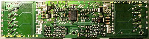
The appearance of MainBoard PA-0157-1TG is shown in the figure below:
PA-0157-1TG
PA-0157-1TG can be used in TVs:
SHIVAKI LCD-2610DVD (Panel 26 "), SHIVAKI STV-26L2 (Panel SHFA060297641).
PSU Advanced
The STV-32L3 model uses the FSP205-4E01 power supply unit using the PFC (Power Factor Correction) node - an active filter of the highest harmonics of the current consumption. In fact, it is a boost converter based on the FAN7530 PWM controller, which eliminates the charge current of the electrolytic capacitor of the rectifier filter directly from the network through open diodes, when its charging current is determined by its reactance.
As a result of the operation of the converter, the envelope of the high-frequency pulses of the input current of the converter will repeat the shape and phase of the input voltage. The health of the PFC node can be indirectly judged by the presence of an increased constant voltage (about + 380V) on the capacitor of the rectifier network in operating mode.
Main features of the SHIVAKI STV-32L3 device:
Installed matrix (LCD panel) LC320WX3 (SL) (A1).
To power the backlight used inverter HS-EE32WL-M.
The necessary supply voltages for all nodes of the SHIVAKI STV-32L3 TV are generated by the FSP205-4E01 power supply module or its analogs using NCP1014, TNY264, FAN7530 (PFC), L6598 (PWM Resonant) microcircuits.
MainBoard - the main board (motherboard) is a module L22E012001, using microcircuits MST9U88L-LF, 25L040, 24C32 and others.
Tuner TDQ-6F6 / T126D provides reception of television programs and tuning to channels.
Additional technical information about the panel:
Brand: LG.Philips LCD
Model: LC320WX3-SLA1
Type: a-Si TFT-LCD, Panel
Diagonal size: 31.5 inch
Resolution: 1366x768, WXGA
Display Mode: S-IPS, Normally Black, Transmissive
Active Area: 697.68x392.26 mm
Surface: Antiglare, Hard coating (3H)
Brightness: 400 cd / m²
Contrast Ratio: 700: 1
Display Colors: 16.7M (8-bit)
Response Time: 8/10 (Tr / Td)
Frequency: 60Hz
Lamp Type: 18 pcs EEFL Embedded (Inverter)
Signal Interface: LVDS (1 ch, 8-bit), 30 pins
Voltage: 12.0 volt.

TV SHIVAKI STV-32L3 with LCD display LC320WX3, diagonal size 32 "(81 cm) 16: 9 format. The brightness of the screen 500 cd / m² is provided with fluorescent lights CCFL (EEFL). Contrast, as the ratio of maximum brightness to minimum, is 1000: 1. It is possible to view images in high quality HD at a resolution of 1366x768 pixels in the standard of graphic decomposition 720p (HD Ready). The input high-frequency or video signal can be processed in analog systems PAL, SECAM, NTSC. Graphic processing and digital signal generation takes place in mill Darts 480i, 480p, 576i, 576p, 720p, 1080i. Stereo sound is realized by two built-in speakers. NICAM STEREO audio processing system is used.
The external interface (communication with other devices) is supported by standard input and output connectors: antenna input (RF), AV x3, audio x4, S-Video, component x2, VGA, HDMI x2. To connect a computer or laptop to this TV model, a VGA (D-Sub 15) connector is used on the TV case, this interface supports resolutions: 640x480, 800x600, 1024x768, 1360x768.
Overall dimensions: With a support of 540x440x200 mm, Without a support of 540x410x80 mm.
The mass of the TV: 23 kg.
Attention! The SHIVAKI STV-32L3 LCD TV panel LC320WX3 (SL) (A1) is its most expensive component.
Avoid hitting the glass and exerting pressure on the screen to avoid permanent damage to the LCD panel!

Friday, 24 April 2020

REPAIR / SERVICING TV SHIVAKI STV-32L6

Technical description and composition of the TV SHIVAKI STV-32L6, type of panel and applicable modules. The composition of the modules.
SHIVAKI
Model: STV-32L6
Chassis / Version: 20ALEU-909-16-0X
Panel: LTA320HM01
MainBoard: 20ALEU-909-16-0X
Tuner: DWC-7053BW-PLL
SHIVAKI
Model: STV-32L6
Chassis / Version: L2M015 (02) 2009.09.06
Panel: T315HW02 V.7
T-CON: T-CON: T370HW02 VC CTRL BD
Inverter (backlight): DS-1931T03013
PWM Inverter: OZ9937GN
Trans Inverter: LKL-103
Power Supply (PSU): BL-PI400103A
MainBoard: L2M015 (02) 2009.09.06
IC MainBoard: MSD106CHL-LF-Z1, 25L3205DM2C, KH25L3206E, TMDS251
Tuner: DTI1-E4I2RH 9916FI
Control: RM510
Technical Specifications STV-32L6
SHIVAKI STV-32L6
General recommendations for repairing TV LCD
Repair of the SHIVAKI STV-32L6 TV is advisable to start with an external examination of all its constituent elements, both internal electronic components and external. Inspection is also subject to body elements, control buttons, screen, connectors and cords. It often happens that some damage to elements or connections will help determine the correct direction of troubleshooting and localization of the defect. Carbonized paint on the upper layer of resistors, electrolytic capacitors of rectifier filters swollen after boiling, cracked soldering at the terminals of heating elements or transformers can often suggest the cause of the defect and possible consequences.
In the case when the STV-32L6 does not turn on, does not respond to the remote control and buttons on the front panel, does not blink lights and does not show any signs of operability, most likely in this case the power supply module is faulty. It is advisable to start the troubleshooting of the power supply module by checking the mains fuse. If it is broken, it is necessary to check first of all the power semiconductor elements - rectifier diodes and the power switch of the converter, which are often found in breakdown conditions in such situations.
In most cases, a breakdown of the N-Fet converter key does not occur for no reason and you should look for other faulty circuit elements that could provoke a defect. This can be dried electrolytic capacitors in the primary circuit, and faulty damper elements, as well as dangling resistors or punched semiconductor elements in the stabilization circuits. Possible defective PWM chip from the manufacturer.
If an active Power Factor Corrector (PFC) is used in the power module circuitry, it is sometimes more difficult to troubleshoot. Knowledge, experience, intuition and skills in such cases have a great advantage for a successful repair.
If the SHIVAKI STV-32L6 does not have an image, there is sound and the channels are switched, there is a possibility of a malfunction of the display backlight, or their power converter - inverter. Sometimes when you turn on the image appears and disappears immediately. In such cases, it is necessary to check the electrolytic capacitors of the power filter of the inverter itself, including in the secondary rectifier of the main PSU.
Repairing the inverter is difficult because in case of any malfunction or emergency, even with uneven wear of the lamps, a protection is triggered, which turns it off for fire safety. Diagnostics become impossible and protection needs to be disabled.
All necessary precautions must be observed when disabling the inverter protection during diagnostics and not leaving it disconnected after the repair is completed.
In cases of attempts to repair the motherboard L2M015 (02) 2009.09.06, it is necessary to check the operability of the power supply circuits of the microcircuits and, if possible, update the software (software). Often, the MB (SSB) card must be replaced in case of complex malfunctions that are difficult to detect. When trying to repair, you should check its elements - MSD106CHL-LF-Z1, 25L3205DM2C, T315HW02 V.7, IJ99F (6), TMDS251, tuner DTI1-E4I2RH 9916FI and replace the failed chips with new ones.
Once again, remind users! Attempts to independently repair the SHIVAKI STV-32L6 TV without the appropriate qualifications and experience can lead to its complete non-repairability!
Main features of the SHIVAKI STV-32L6 device:
Installed matrix (LCD panel) T315HW02 V.7.
The matrix control uses the Timing Controller (T-CON) T-CON: T370HW02.
To power the backlight, an inverter DS-1931T03013 is used, it is controlled by the PWM controller OZ9937GN. A transformer LKL-103 is installed in the inverter converter.
The formation of the necessary supply voltages for all nodes of the SHIVAKI STV-32L6 TV is carried out by the BL-PI400103A power module, or its analogues.
MainBoard - the main board (motherboard) is an L2M015 module, using microchips MSD106CHL-LF-Z1, 25L3205DM2C, KH25L3206E, TMDS251 and others.
The DTI1-E4I2RH 9916FI tuner provides TV reception and channel tuning.
Additional technical information about the panel:
Brand: AUO
Model: T315HW02 V7
Type: a-Si TFT-LCD, Panel
Diagonal size:31.5 inch
Resolution: 1920x1080, FHD
Display Mode: AMVA3, Normally Black, Transmissive
Active Area: 698.4x392.85 mm
Surface: Antiglare (Haze 11%), Hard coating (3H)
Brightness: 450 cd / m²
Contrast Ratio: 4000: 1
Display Colors: 16.7M (8-bit), CIE1931 72%
Response Time: 6.5 (G to G)
Frequency: 60Hz
Lamp Type: 4 pcs CCFL Embedded (Inverter)
Signal Interface: LVDS (2 ch, 8-bit), 51 pins
Voltage: 12.0V

TV SHIVAKI STV-32L6 with LCD T315HW02, diagonal size 32 "(81 cm) 16: 9 format. The brightness of the screen 400 cd / m² is provided by fluorescent lights CCFL (EEFL). Contrast, as the ratio of maximum brightness to minimum, is 1200: 1. It is possible to view images in high quality HD at a resolution of 1366x768 pixels in the standard for graphic decomposition 720p (HD Ready). The input high-frequency or video signal can be processed in analog systems PAL, SECAM, NTSC. Graphic processing and digital signal generation takes place in mill Darts 480i, 480p, 576i, 576p, 720p, 1080i.
The power of the sound system 10 W (2x5 W) provide two speakers. The audio processing system NICAM STEREO is used.
The external interface (communication with other devices) is supported by standard input and output connectors: antenna input (RF), AV, S-Video, component, SCART x2, VGA, HDMI x2. An output for connecting headphones is provided. To connect a computer or laptop to this TV model, a VGA (D-Sub 15) connector is used on the TV case, this interface supports resolutions: 640x480, 800x600, 1024x768.
Overall dimensions: With stand 795x582x233 mm, Without stand 581x371x43 mm.
TV Weight: 15 kg.
Attention! The T315HW02 V.7 panel of the SHIVAKI STV-32L6 LCD TV is its most expensive component.
Avoid hitting the glass and exerting pressure on the screen to avoid permanent damage to the LCD panel!

REPAIR / SERVICING TV SHIVAKI STV-26L2

Technical description and composition of the TV SHIVAKI STV-26L2, type of panel and applicable modules. The composition of the modules.
SHIVAKI
Model: STV-26L2
Panel: SHFA060297641
Inverter (backlight): VT71008.90 Logah REV: 0
PWM Inverter: LM339A, LM393
MOSFET Inverter: 4612
Power Supply (PSU): MLT070A
PWM Power: ML4800CS, FAN7601, LM358
MOSFET Power: 20N60, 9N50, 5N60
MainBoard: PA-0157-1TG LM21C UOC3
IC MainBoard: MST6151A, TDA12063H, AN17820N, K4S161622H-UC60,
Tuner: TDQ6F6T1260
Technical Specifications STV-26L2
SHIVAKI STV-26L2
General recommendations for repairing TV LCD
It is advisable to start the diagnostics of a malfunction of the SHIVAKI STV-26L2 KALININGRAD TV, like all others, with an external examination of possible changes, both external and internal elements. Any external damage can sometimes prompt the repairman to take further steps to determine the malfunction of the TV and localize the defect. Swollen electrolytic or cermet capacitors, charred resistors, ring cracks in the soldered terminals of the elements - all this can significantly help the master to determine the causes and consequences of the malfunction of the TV.
Malfunctions of the MLT070A power supply module can be expressed in different ways, for example, SHIVAKI STV-26L2 KALININGRAD does not turn on at all and the control lamps on its front panel do not light up and do not blink, there are no signs of operability. When diagnosing and repairing the power supply, first of all, it is necessary to check the fuse and, if it is broken, it is necessary to identify the cause. Often in such cases, an avalanche (thermal) breakdown is detected in the power semiconductor elements of the module — rectifier diodes or power switch 20N60, 9N50, 5N60.
It should be remembered that the N-FET keys used in flyback converters rarely fail for no reason that must be sought by checking other elements of the circuit. Often the breakdown is caused by malfunctions of electrolytic capacitors or semiconductor elements in the primary circuit, or by a break in the resistors in the stabilization circuits. The PWM controller chip ML4800C6, LM358, 20N60 can also cause a breakdown of the power switch of the converter.
It is somewhat more difficult to look for a malfunction in the converter of the power module with an active KKM (power factor corrector).
If the SHIVAKI STV-26L2 KALININGRAD does not have an image, but there is sound and the TV is controlled from the remote control, a malfunction in the display backlight nodes is likely. The lamps or the power converter - inverter may be faulty. Often in such cases, when you turn on the TV, an image appears and immediately disappears. First of all, it is necessary to verify the operability of the electrolytic capacitors of the rectifier filter supplying the inverter, and check the LCD lamps by connecting external and obviously serviceable for diagnosis to the connectors.
In most cases, the diagnosis and repair of the VT71008.90 Logah REV: 0 inverter is difficult due to the organization of protection, which turns it off in emergency cases to avoid fires during short circuits or open circuits in high voltage circuits and during lamp depressurization. Often, repairmen block the protection circuits in order to make the necessary measurements at the inverter control points to identify the causes of the defect.
All necessary precautions must be observed when disabling the inverter protection during diagnostics and not leaving it disconnected after the repair is completed.
On the tun TDQ6F6T1260 motherboard, in case of a malfunction, you should first check the operation of all power supply stabilizers of the microcircuits and, if necessary, update the software (software). Often, the MB (SSB) card must be replaced in case of complex malfunctions that are difficult to detect. When trying to repair, you should check its elements - MST6151A, TDA12063H, AN17820N, K4S161622H-UC60, and replace failed chips with new ones.
Owners and users of the SHIVAKI STV-26L2 KALININGRAD TV must remember that self-repair without special knowledge, skills and qualifications can be fraught with negative consequences, which can lead to complete non-repairability of the device!
Repair MainBoard
The appearance of MainBoard PA-0157-1TG is shown in the figure below:
PA-0157-1TG
PA-0157-1TG can be used in TVs:
SHIVAKI LCD-2610DVD (Panel 26 inches), SHIVAKI STV-26L2 (Panel SHFA060297641).
The appearance of the power supply
Main features of the SHIVAKI STV-26L2 device:
Installed matrix (LCD panel) SHFA060297641.
To power the backlight, an inverter VT71008.90 is used, it is controlled by the PWM controller LM339A, LM393. As power elements of the inverter, keys of type 4612 are used.
The necessary supply voltages for all nodes of the SHIVAKI STV-26L2 TV are generated by the MLT070A power supply module or its analogs using ML4800CS, FAN7601, LM358 microcircuits and power switches of the type 20N60, 9N50, 5N60.
MainBoard - the main board (motherboard) is a module PA-0157-1TG, using chips MST6151A, TDA12063H, AN17820N, K4S161622H-UC60, and others.
The TDQ6F6T1260 tuner provides TV reception and channel tuning.

TV SHIVAKI STV-26L2 with LCD SHFA060297641, diagonal size 26 "(66 cm) 16: 9 format. The brightness of the screen is 500 cd / m² backlight fluorescent lamps CCFL (EEFL). Contrast, as the ratio of maximum brightness to minimum, is 800: 1. It is possible to view images in high quality HD at a resolution of 1366x768 pixels in the standard for graphic decomposition 720p (HD Ready). The input high-frequency or video signal can be processed in analog systems PAL, SECAM, NTSC. Graphic processing and digital signal generation takes place in st Andartach 480i, 480p, 576i, 576p, 720p, 1080i. Stereo sound is realized by two built-in speakers. The audio processing system NICAM STEREO is used.
The external interface (communication with other devices) is supported by standard input and output connectors: antenna input (RF), AV, S-Video, component, SCART, RGB, VGA, DVI HDCP. To connect a computer or laptop to this TV model, a VGA (D-Sub 15) connector is used on the TV case, this interface supports resolutions: 640x480, 800x600, 1024x768, 1280x1024, 1360x768.
Dimensions: With stand 798x626x226 mm, Without stand 581x371x43 mm.
Attention! The SHFAAK6060297641 panel of the SHIVAKI STV-26L2 LCD TV is its most expensive component.
Avoid hitting the glass and exerting pressure on the screen to avoid permanent damage to the LCD panel!

REPAIR / SERVICING TV SHIVAKI STV-26L6

Technical description and composition of the SHIVAKI STV-26L6 TV, type of panel and applicable modules. The composition of the modules.
SHIVAKI
Model: STV-26L6
Panel: V260B1-L11 Rev C1
Inverter (backlight): VIT70063.50 Rev.3
PWM Inverter: OZ964GN
MOSFET Inverter: P4404EDG, P2504BDG
Trans Inverter: T51.0191.211
Power Supply (PSU): LK4180-000B
PWM Power: L6599D, L6562D, TDA4863G
MOSFET Power: P11NK50ZFP, FQPF5N60C
MainBoard: L2M015 (03) DTI1-E4I2RH, L2M015 (02)
IC MainBoard: MSD106CHL-LF-Z1, KH25L3206E, 25L3205DM2C
Tuner: DTI1-E412RH
Technical Specifications STV-26L6
SHIVAKI STV-26L6
General recommendations for repairing TV LCD
Repair of the SHIVAKI STV-26L6 TV is better to start with a thorough external inspection and diagnosis of the malfunction. It is advisable to carefully examine the internal and external components. Many visible signs make it possible to determine the future direction of troubleshooting and localization of the defect. Carbonized paint on the upper layer of resistors, electrolytic capacitors of rectifier filters swollen after boiling, cracked soldering at the terminals of heating elements or transformers can often suggest the cause of the defect and possible consequences.
Sometimes the SHIVAKI STV-26L6 TV simply does not turn on. No control lights on the front panel are lit or blinking, the TV does not respond to the remote control and does not make any sounds or any signs of life when turned on. The most likely cause of the malfunction is the failure of the common LKL- power supply module. When diagnosing and repairing the LKL-power supply unit, it is first necessary to check the fuse, and if it breaks, the power switch and rectifier bridge diodes should be checked for avalanche (thermal) breakdown.
It should be remembered that the N-FET keys used in flyback converters rarely fail for no reason that must be sought by checking other elements of the circuit. Often the breakdown is caused by malfunctions of electrolytic capacitors or semiconductor elements in the primary circuit, or by a break in the resistors in the stabilization circuits. The PWM controller chip can also cause a breakdown of the power switch of the converter.
Diagnostics of power modules with a Power Factor Corrector (CMC) is somewhat more complicated and requires a more detailed approach.
If the SHIVAKI STV-26L6 TV does not have an image, but there is sound, the malfunction should be sought in the power converter of the backlight (inverter). It is also necessary to check the serviceability of the electrolytic capacitors of the filter of the secondary rectifiers of the PSU (power supply) for an overstated ESR.
Repair of the inverter can often be somewhat complicated by the use of special protection circuits, which are designed to disconnect it in emergency cases for fire safety during depressurization of lamps, or short circuits or breaks in high-voltage circuits and connections. Sometimes it becomes necessary for diagnostic purposes to block the protection circuits in order to be able to make the necessary measurements at the control points of the circuit.
In these cases, special care must be taken in view of the risk of failure of the power elements. After completing all repair work, it is imperative to restore the protection circuits for full and safe further operation of the TV by the user.
On the motherboard, in case of a malfunction, it is first of all necessary to check the operability of all power stabilizers of the microcircuits and, if necessary, update the software (software). In some cases, it is necessary to check or replace (if necessary) the elements of the MB board (SSB) - MSD106CHL-LF-Z1, KH25L3206E.
Attention to users! Self-repair of a SHIVAKI STV-26L6 TV without the appropriate qualifications and experience can lead to its complete non-repairability!
Main features of the SHIVAKI STV-26L6 device:
Installed matrix (LCD panel) V260B1-L11 Rev C1.
The VIT70063.50 inverter is used to power the backlight lamps, it is controlled by the OZ964GN PWM controller. A transformer T51.0191.211 is installed in the inverter converter. As power elements of the inverter, keys of the type P4404EDG, P2504BDG are used.
The necessary supply voltages for all nodes of the SHIVAKI STV-26L6 TV are generated by the power module LK4180-000B, or its analogs using microchips L6599D, L6562D, TDA4863G and power switches of the type P11NK50ZFP, FQPF5N60C.
MainBoard - the main board (motherboard) is an L2M015 module, using microchips MSD106CHL-LF-Z1, KH25L3206E, 25L3205DM2C and others.
The DTI1-E412RH tuner provides TV reception and channel tuning.
Additional technical information about the panel:
Brand: CMO
Model: V260B1-L11
Type: a-Si TFT-LCD, Panel
Diagonal size: 26.0 inch
Resolution: 1366x768, WXGA
Display Mode: TN, Normally White, Transmissive
Active Area: 575.769x323.712 mm
Surface: Antiglare (Haze 25%), Hard coating (3H)
Brightness: 500 cd / m²
Contrast Ratio: 800: 1
Display Colors: 16.2M (6-bit + FRC), CIE1931 72%Response Time: 3/5 (Tr / Td)
Frequency: 60Hz
Lamp Type: 5 pcs CCFL Embedded (Inverter)
Signal Interface: LVDS (1 ch, 8-bit), 30 pins
Voltage: 12.0V

 TV SHIVAKI STV-26L6 with LCD V260B1-L11, diagonal size 26 "(66 cm) 16: 9 format. The brightness of the screen is 500 cd / m² backlight fluorescent lamps CCFL (EEFL). Contrast, as the ratio of maximum brightness to the minimum is 800: 1. You can view images in high quality HD at a resolution of 1366x768 pixels in the standard for graphic decomposition 720p (HD Ready). The input high-frequency or video signal can be processed in analog systems PAL, SECAM, NTSC. Graphic processing and digital signal generation going on in a hundred Dart 480i, 480p, 576i, 576p, 720p, 1080i.
The power of the sound system 10 W (2x5 W) provide two speakers. The audio processing system NICAM STEREO is used.
The external interface (communication with other devices) is supported by standard input and output connectors: antenna input (RF), AV, VGA. To connect a computer or laptop to this TV model, a VGA (D-Sub 15) connector is used on the TV case, this interface supports resolutions: 640x480, 800x600, 1024x768.
Overall dimensions: With a support of 581x406x180 mm, Without a support of 581x371x43 mm.
Attention! The SHIVAKI STV-26L6 LCD TV panel V260B1-L11 Rev C1 is its most expensive component.
Avoid hitting the glass and exerting pressure on the screen to avoid permanent damage to the LCD panel!

REPAIR / SERVICING TV SHIVAKI STV-32L2

Technical description and composition of the SHIVAKI STV-32L2 TV, type of panel and applicable modules. The composition of the modules.
SHIVAKI
Model: STV-32L2
Chassis / Version: LM21C
Panel: T315XW01 V.5
Power Supply (PSU): MLT070A
PWM Power: ML4800CS, FAN7601, LM358
MOSFET Power: 20N60, 9N50, 5N60
MainBoard: LM21E12U03 PA-0143, PA-0142 --- 4TG
IC MainBoard: TDA12063H1 / N1F80 MCT6151A 24c16 NVM
Tuner: TDQ-6F6 / T126D
SHIVAKI
Model: STV-32L2
Chassis / Version: PA-0118-2-3TG
Panel: T315XW02
T-CON: T315XW02 EM638325TS-6G
Inverter (backlight): 4H.V0708.381 / B1 mod. V070
PWM Inverter: OZ964SN, EZ3H646_339
Trans Inverter: 4010Q648.110 (GP)
Power Supply (PSU): ML4800SC
PWM Power: FAN7601
MainBoard: PA-0118-2-3TG L22E012001
IC MainBoard: MST9U88L-LF, 24LC32AI, TDA7297
Tuner: TDQ-6F6 / T126D (TDA6509ATT)
Technical Specifications STV-32L2
SHIVAKI STV-32L2
General recommendations for repairing TV LCD
Like any other TV, it is advisable to start the SHIVAKI STV-32L2 repair with an external examination of the visible changes in the external and internal elements. Many visible signs make it possible to determine the future direction of troubleshooting and localization of the defect. Electrolytic capacitors of filters with a swollen casing, as well as ring cracks formed in the soldered leads of heating elements, or a layer of coal on burnt resistors sometimes tell the repairman the causes of the malfunction and possible consequences.
In the absence of any signs of operability, when the SHIVAKI STV-32L2 KALININGRAD does not turn on and does not signal anything with the control lights on the panel, the ML4800SC power supply module is most likely faulty. The diagnostics of the power supply should always be started by checking the fuse and, if it is broken, it is first necessary to check the rectifier bridge diodes and the power switch for the possibility of an avalanche or thermal breakdown.
It should be remembered that the N-FET keys used in flyback converters rarely fail for no reason that must be sought by checking other elements of the circuit. Often the breakdown is caused by malfunctions of electrolytic capacitors or semiconductor elements in the primary circuit, or by a break in the resistors in the stabilization circuits. The FAN7601 PWM controller chip can also cause a breakdown of the power switch of the converter.
If the power module uses an active KKM circuit (power factor control), troubleshooting is somewhat more complicated.
Sometimes the SHIVAKI STV-32L2 TV does not have an image, but there is sound, or the image appears and immediately disappears. In this case, there is a high probability of a malfunction of the backlight converter, or of the lamps themselves, which can be checked by replacement. In such cases, it is necessary to verify the serviceability of all electrolytic capacitors of the filter according to the power supply of the inverter itself, including in the power supply unit (power supply unit).
Repair of the inverter 4H.V0708.381 / B1 mod. V070 is complicated by the fact that in case of any malfunction or emergency, even with uneven wear of the lamps, a protection is triggered, which turns it off for fire safety purposes. Diagnostics become impossible and protection needs to be disabled.
In such cases, the risk of failure of the power elements of the inverter is most likely, and special care is required during work, and after their completion, it is necessary to restore the protection circuit for further safe operation of the TV by the owner in normal mode.
Repair of the motherboard must begin with the diagnosis and verification of all linear stabilizers or power converters of its microcircuits. Sometimes it may be necessary to update the software (software) - flashing FLASH or EEPROM. Often, the MB (SSB) card must be replaced in case of complex malfunctions that are difficult to detect. When trying to repair, you should check its elements - MST9U88L-LF, 24LC32AI, TDA7297, tun TDQ-6F6 / T126D (TDA6509ATT) and replace failed chips with new ones.
We recommend the owners of the STV-32L2 TV for repair only to qualified specialists with experience! Self-repair attempts without the appropriate knowledge and skills can lead to serious negative consequences!


Main features of the SHIVAKI STV-32L2 device:
Installed matrix (LCD-panel) T315XW02.
The matrix control uses the Timing Controller (T-CON) T315XW02.
To power the backlight, an inverter 4H.V0708.381 is used, it is controlled by the PWM controller OZ964SN, EZ3H646_339. A transformer 4010Q648.110 (GP) is installed in the inverter converter.
The necessary supply voltages for all nodes of the SHIVAKI STV-32L2 TV are generated by the ML4800SC power supply module or its analogs using FAN7601 microcircuits.
MainBoard - the main board (motherboard) is a PA-0118-2-3TG module, using microcircuits MST9U88L-LF, 24LC32AI, TDA7297 and others.
The tuner TDQ-6F6 / T126D (TDA6509ATT) provides the reception of television programs and tuning to channels.

Additional technical information about the panel:
Brand: AUO
Model: T315XW02 VU
Type: a-Si TFT-LCD, Panel
Diagonal size: 31.5 inch
Resolution: 1366x768, WXGA
Display Mode: AMVA, Normally Black, Transmissive
Active Area: 697.685x392.256 mm
Surface: Antiglare (Haze 11%), Hard coating (3H)
Brightness: 400 cd / m²
Contrast Ratio: 3000: 1
Display Colors: 16.7M (8-bit), CIE1931 72%
Response Time: 6.5 (G to G)
Frequency: 60Hz
Lamp Type: 4 pcs CCFL Without Driver
Signal Interface: LVDS (1 ch, 8-bit), 30 pins
Voltage: 12.0V


TV SHIVAKI STV-32L2 with LCD T315XW02, diagonal size 32 "(81 cm) in 16: 9 format. The brightness of the screen is 500 cd / m² with fluorescent lights CCFL (EEFL). Contrast, as the ratio of maximum brightness to minimum, is 1000: 1. You can view images in high quality HD at a resolution of 1366x768 pixels in the standard for graphic decomposition 720p (HD Ready). The input high-frequency or video signal can be processed in analog systems PAL, SECAM, NTSC. Stereo sound is realized by two built-in speakers. The system is used and audio processing NICAM STEREO.
The external interface (communication with other devices) is supported by standard input and output connectors: antenna input (RF), AV, S-Video, SCART x2, RGB, VGA, HDMI.
Overall dimensions: With a support of 540x440x200 mm, Without a support of 540x410x80 mm.
Attention! The T315XW02 panel of the SHIVAKI STV-32L2 LCD TV is its most expensive component.
Avoid hitting the glass and exerting pressure on the screen to avoid permanent damage to the LCD panel!

REPAIR / SERVICING TV SHIVAKI STV-22L6

Technical description and composition of the TV SHIVAKI STV-22L6, type of panel and applicable modules. The composition of the modules.
SHIVAKI
Model: STV-22L6
Chassis / Version: L2M18 (03) 20-ASCH903-14-0X
Panel: L216B1-L02 Rev. C1 // V216B1-L01
T-CON: V216B1-XC01 CM1671B
Inverter (backlight): LK-IN220417A
PWM Inverter: OB3302CP
MOSFET Inverter: AO4828
Power Supply (PSU): HGPKS03 REV.5-2
PWM Power: LD7575PS, STK0765
MainBoard: L2M18 (03) - 20-ASCH903-14-0X - BLRT903N-01-H // L2M23 (01)
IC MainBoard: EN25F40, 24C32, SA7454, MX25L3205, FT24C32A
Tuner: UVL7705VEAW1
Technical Specifications STV-22L6
SHIVAKI STV-22L6
General recommendations for repairing TV LCD
Like any other TV, it is advisable to start the SHIVAKI STV-22L6 repair with an external examination of the visible changes in the external and internal elements. Often, for certain external signs, the repairman can draw some conclusions about the reasons for the failure of certain elements of the circuit even before the necessary measurements are made, which will determine the further algorithm for troubleshooting and localizing the defect. Carbonized paint on the upper layer of resistors, electrolytic capacitors of rectifier filters swollen after boiling, cracked soldering at the terminals of heating elements or transformers can often suggest the cause of the defect and possible consequences.
In cases where the SHIVAKI STV-22L6 TV does not turn on, does not respond to the remote control and buttons, no indicators on the front panel light up or blink, and there are no sounds and no signs of operability when turning on, the power module is most likely faulty or, what it happens much less often - there is no processor power on the motherboard. If the mains fuse is broken in the power supply, in most cases a breakdown of the power switch is detected, which can be integrated with the PWM controller, or a separate field-effect transistor can be used. The rectifier bridge diodes and the electrolytic capacitor of the mains rectifier filter should also be checked.
The reasons for the breakdown of the power switch of the flyback converter of the power module can be different, for example, a malfunction of semiconductor cells or electrolytic capacitors in the stabilization circuits of the primary circuit, as well as a failure in the operation of the PWM controller chip or breakage of the resistors in its bundle.
When using the Active Power Factor Correction (CMC) circuitry in the power module, the search for faulty elements is somewhat more complicated.
If there is no image when you turn on the SHIVAKI STV-22L6, or it appears for a second and disappears completely, but there is sound, most likely either the backlight lamps or their power converter (inverter) are faulty. It is necessary to check the electrolytic capacitors of the filter of the secondary rectifiers in the general power supply unit.
When repairing the inverter, it is often necessary for diagnostics to turn off the protection, which, for the purpose of fire safety, turns it off in any emergency situation, for example, during a malfunction or uneven wear of the lamps, which makes it difficult to find a defect.
Turning off the protection for diagnostic purposes, it must be remembered that in this case there is a risk of failure of the power elements of the inverter. Upon completion of the diagnosis, all regular protection circuits should be restored.
When trying to repair the motherboard, you should first check the serviceability of linear stabilizers or power converters of microcircuits and, if necessary, update the software (software). In some cases, to repair the MB board (SSB), it may be necessary to replace the chips - EN25F40, 24C32, SA7454, MX25L3205, FT24C32A with new or obviously working ones.
It should be remembered! Attempts to repair the SHIVAKI STV-22L6 TV, in the absence of the necessary qualifications and experience, are categorically not recommended and are fraught with negative consequences, up to the complete non-repairability of the device!


SCHEMATIC DIAGRAM  / SERVICE MANUAL   ------------------>    SHIVAKI STV19L6, STV22L6, CHASSIS L2M18, CPU: MST9E19.zip
FIRMWARE FOR SPI FLASH  ----------->   SHIVAKI STV22L6, Main: L2M23(01),Panel: V216B1-L01, T-CON: V216B1-XC01


 The appearance of the MainBoard L2M18 (03) is shown in the figure below:
L2M18 (03)
L2M18 (03) can be used in TVs:
BBK LD1913SU (Panel HT185WX1-100), BBK LD2213SU Ver1 (Panel M216H1-L01 RevC1 LTA216AT01), BBK LD2213SU Ver2 (Panel LCD LC220WXE-TBA1), SHIVAKI STV-22L6 (Panel L216B1-L02 Rev.C1).
Main features of the SHIVAKI STV-22L6 device:
Installed matrix (LCD panel) L216B1-L02 Rev. C1 or V216B1-L01.
The matrix control uses the Timing Controller (T-CON) V216B1-XC01.
To power the backlight, an inverter LK-IN220417A is used, it is controlled by the PWM controller OB3302CP. As power elements of the inverter, keys of the type AO4828 are used.
The necessary supply voltages for all nodes of the TV SHIVAKI STV-22L6 are formed by the power module HGPKS03, or its analogs using microcircuits LD7575PS, STK0765.
MainBoard - the main board (motherboard) is an L2M18 (03) module, using chips EN25F40, 24C32, SA7454, MX25L3205, FT24C32A and others.
The tuner UVL7705VEAW1 provides reception of television programs and tuning to channels.

Information from an alternative source:
SHIVAKI STV-22L6
Panel Type (Matrix): V216B1-L01,
Motherboard: L2M23 (01), MST9E19B-LF, EN25F40-100GCP, 24C32WP, TDA9886TS, MP1484EN, SGM330A x2, 24C02WP x2, SA7454, UTC4558E, Tuner: UVL7705VEAW1
T-con: V216B1-XC01, CM1671B
Invertor: LK-IN220417A, OB3302CP, AO4828,
PSU: HGPKS03 / REV5-2, LD7575PS, STK0765, MBFR20100CT
Remote control: BT0534, Circuit L2M23 (01),

TV SHIVAKI STV-22L6 with LCD L216B1-L02, diagonal size 22 "(55 cm) 16:10 format. The brightness of the screen is 300 cd / m² with fluorescent lights CCFL (EEFL). Contrast, as the ratio of maximum brightness to the minimum is 1000: 1. You can view images in high quality HD at a resolution of 1680x1050 pixels in the standard for graphic decomposition 720p (HD Ready). The input high-frequency or video signal can be processed in analog systems PAL, SECAM, NTSC. Graphic processing and digital signal generation going on in st andarts 480i, 480p, 576i, 576p, 720p, 1080i.
The power of the sound system 4 W (2x2 W) provide two speakers. The audio processing system NICAM STEREO is used.
The external interface (communication with other devices) is supported by standard input and output connectors: antenna input (RF), AV, SCART, RGB, VGA, HDMI. An output for connecting headphones is provided. To connect a computer or laptop to this TV model, a VGA (D-Sub 15) connector is used on the TV case, this interface supports resolutions: 640x480, 800x600, 1024x768, 1280x1024, 1360x768.
Overall dimensions: With a support of 581x406x180 mm, Without a support of 581x371x43 mm.
Attention! The SHIVAKI STV-22L6 LCD TV panel L216B1-L02 Rev. C1 is its most expensive component.
Avoid hitting the glass and exerting pressure on the screen to avoid permanent damage to the LCD panel!

REPAIR / SERVICING TV SHIVAKI STV-20L3

Technical description and composition of the TV SHIVAKI STV-20L3, type of panel and applicable modules. The composition of the modules.
SHIVAKI
Model: STV-20L3
Panel: SHFA070089763
Inverter (backlight): Haider IVA20601D REV03 PC40003J --- 1CG CCE-VOE166702
PWM Inverter: OZ9938GN (16) PH5ADFAN7311
MOSFET Inverter: FDS 8958A (SO8)
Trans Inverter: TM-1013 ---- 1F FURI-070917
Power Supply (PSU): Haider HDAD60W102-OF REV2.1 CCE-VOE166702
PWM Power: LD7552BP (SO8) STK0766
MOSFET Power: 6N52JP02 (SO8)
MainBoard: FA20176-2--31G PA-20176-2—2TG
IC MainBoard: TDA15021H / N1C00, 24C16AN, MST9010SA-LF, AN17825A, 74HC153D, KF9650
Tuner: TDQ-6F6 / W126D
Control: BT-0451C ... CBG
Technical Specifications STV-20L3
SHIVAKI STV-20L3
General recommendations for repairing TV LCD
It is advisable to start diagnosing the malfunction of the SHIVAKI STV-20L3 TV, like all others, with an external examination of possible changes, both external and internal elements. Visible damage to elements can sometimes suggest further directions for finding a defect before starting the necessary measurements. Ring cracks in the soldering of the leads of the heating elements, swollen electrolytic capacitors, a charred paint layer on the resistors - all this for the repairman can be a hint in the assumptions about the causes and consequences of the malfunction.
Sometimes the SHIVAKI STV-20L3 TV simply does not turn on. No control lights on the front panel are lit or blinking, the TV does not respond to the remote control and does not make any sounds or any signs of life when turned on. The most likely cause of the malfunction is the failure of the Haider HDAD60W102-OF REV2.1 CCE-VOE166702 common power supply module. If the mains fuse is broken in the power supply, in most cases a breakdown of the power switch 6N52JP02 (SO8) is detected, which can be integrated with the PWM controller, or a separate field-effect transistor can be used. The rectifier bridge diodes and the electrolytic capacitor of the mains rectifier filter should also be checked.
It should be remembered that the N-FET keys used in flyback converters rarely fail for no reason that must be sought by checking other elements of the circuit. Often the breakdown is caused by malfunctions of electrolytic capacitors or semiconductor elements in the primary circuit, or by a break in the resistors in the stabilization circuits. The PWM controller chip LD7552BP (SO8) STK0766 can also cause a breakdown of the power switch of the converter.
In cases where the Power Factor Corrector (PFC) is used in the power supply, troubleshooting can be a bit more complicated.
Sometimes the SHIVAKI STV-20L3 TV does not have an image, but there is sound, or the image appears and immediately disappears. In this case, there is a high probability of a malfunction of the backlight converter, or of the lamps themselves, which can be checked by replacement. In such cases, it is necessary to verify the serviceability of all electrolytic capacitors of the filter according to the power supply of the inverter itself, including in the power supply unit (power supply unit).
Diagnostics of the Haider IVA20601D REV03 PC40003J inverter --- 1CG CCE-VOE166702 can be difficult due to the protection being triggered by the designers to prevent negative consequences or fires in emergency cases, for example, during short circuits or open circuits in the lamp power supply circuit, as well as their possible depressurization. To make the necessary measurements at control points or to take the necessary waveforms, repairmen have to block the protection circuits in order to be able to diagnose.
It should be remembered that when the protection is turned off, there is always a risk of failure of the power elements of the inverter during diagnosis. After repair, it is necessary to restore all standard converter protection circuits.
When trying to repair the motherboard, you should first check the serviceability of linear stabilizers or power converters of microcircuits and, if necessary, update the software (software). If it is not possible to replace the MB (SSB) card, you need to check the health of its elements - TDA15021H / N1C00, 24C16AN, MST9010SA-LF, AN17825A, 74HC153D, KF9650. Defective components should be replaced.
Attention to users! Self-repair of a SHIVAKI STV-20L3 TV without the appropriate qualifications and experience can lead to its complete non-repairability!

Main features of the SHIVAKI STV-20L3 device:
Installed matrix (LCD panel) SHFA070089763.
A Haider inverter is used to power the backlight, controlled by the OZ9938GN (16) PH5ADFAN7311 PWM controller. The transformer TM-1013 ---- 1F FURI-070917 is installed in the inverter converter. As power elements of the inverter, keys of the FDS 8958A (SO8) type are used.
The necessary supply voltages for all nodes of the SHIVAKI STV-20L3 TV are generated by the Haider power supply module or its analogs using LD7552BP (SO8) STK0766 microcircuits and 6N52JP02 (SO8) type power switches.
MainBoard - the main board (motherboard) is an FA20176-2-31G module, using TDA15021H / N1C00, 24C16AN, MST9010SA-LF, AN17825A, 74HC153D, KF9650, and others microcircuits.
The TDQ-6F6 / W126D tuner provides TV reception and channel tuning.
Information from an alternative source:
SHIVAKI STV-20L3 KALININGRAD
Panel Type (Matrix) :, SHFA070089763 Central Board PA-20176-2—2TG:, TDA15021H / N1C00, 24C16AN, MST9010SA-LF, AN17825A, 74HC153D, KF9650 Tuner :, TDQ-6F6 / W126D Power Supply CCE-VE16, Saniton CCE-VO1616 -32-004 - imp. Trans, Cosmo1010 / 817 - optocoupler, A3762C Inverter PC40003J --- 1CG \ CCE-VOE166702 :, PH5AD \ FAN7311, 8958A- 4pcs, Trans - TM-1013 ---- 1F \ FURI-070917 - 6pcs..

SHIVAKI STV-20L3 TV with SHFA070089763 LCD, 20 "diagonal size, 4: 3 format. Screen brightness of 450 cd / m² is provided by CCFL (EEFL) fluorescent lamps. Contrast ratio, as the ratio of maximum brightness to minimum, is 700: 1 The input high-frequency or video signal can be processed in analog systems PAL, SECAM, NTSC. Graphic processing and digital signal generation takes place in the standards 480i, 480p, 576i, 576p.
The power of the acoustic system of sound 6 W (2x3W) provide two speakers. The audio processing system NICAM STEREO is used.
The external interface (communication with other devices) is supported by standard input and output connectors: antenna input (RF), AV, audio x2, SCART, RGB, VGA. An output for connecting headphones is provided. To connect a computer or laptop to this TV model, a VGA (D-Sub 15) connector is used on the TV case, this interface supports resolutions: 640x480, 800x600.
Overall dimensions: With a support of 540x440x200 mm, Without a support of 540x410x80 mm.
Attention! The panel SHFA070089763 LCD-TV SHIVAKI STV-20L3 is its most expensive component.
Avoid hitting the glass and exerting pressure on the screen to avoid permanent damage to the LCD panel!

REPAIR / SERVICING TV SHIVAKI STV-20L2

Technical description and composition of the TV SHIVAKI STV-20L2, type of panel and applicable modules. The composition of the modules.
SHIVAKI
Model: STV-20L2
Panel: HT201V01-101
Inverter (backlight): 3V0 + 94V-0 SFP2066E_Ver1.0
PWM Inverter: BIT3106A
Power Supply (PSU): Adapter SAWA-01-483 (12v 5A) or BPD0023A - DZG
PWM Power: SG6841SZ
MOSFET Power: BA6N62 (SOIC-8 = OA4606), BA7K28
MainBoard: PA-0153 2TG SHFA060213535
IC MainBoard: MSP1250G -5.0, NTDA9381C330EG, TDA8959, AN17825A, MST9141B, AN17825A, 24C16
Tuner: TDQ-6F6 / W126D
Technical Specifications STV-20L2
SHIVAKI STV-20L2
General recommendations for repairing TV LCD
Repair of the SHIVAKI STV-20L2 TV is advisable to start with an external examination of all its constituent elements, both internal electronic components and external. Inspection is also subject to body elements, control buttons, screen, connectors and cords. Any external damage can sometimes prompt the repairman to take further steps to determine the malfunction of the TV and localize the defect. In some cases, faulty elements can be seen with the naked eye, for example, charred resistors or swollen metal-ceramic capacitors, or electrolytic in rectifier filters. Ring cracks formed in the soldered terminals of transformers or heating elements of the circuit are also frequent sources of many malfunctions with a variety of external manifestations.
In cases when the SHIVAKI STV-20L2 TV does not turn on, does not respond to the remote control and buttons, any indicators on the front panel do not light up or blink, and there are no sounds and no signs of operability when turning on, the AC adapter SAWA power supply module is most likely to be faulty -01-483 (12v / 5A) or BPD0023A - DZG or, which is much less common, there is no processor power on the motherboard. The diagnostics of the power supply should always be started by checking the fuse and, if it is broken, the first thing to do is to check the rectifier bridge diodes and the power switch BA6N62 plan 8n (4606). BA7K28 for the probability of an avalanche or thermal breakdown.
It should be borne in mind that in the repair practice it is extremely rare that key transistors of the N-FET type fail for no reason that should be looked for by checking other components, for example, a breakdown of the key can provoke faulty elements of the damper circuits, either dried electrolytic capacitors or dangling resistors of the primary circuit of the PSU, involved in the stabilization process. In this case, all semiconductor elements of the strapping of the BIT3106A pit PWM controller chip are subject to verification. SG6841SZ 2AO7512 (8H), which is preferably checked by replacement.
If an active Power Factor Corrector (PFC) is used in the power module circuitry, it is sometimes more difficult to troubleshoot. Knowledge, experience, intuition and skills in such cases have a great advantage for a successful repair.
In cases where the SHIVAKI STV-20L2 TV has lost an image, and the sound is there and all the other functions are operational, there is a possibility of a malfunction of the inverter (converter for powering the backlight). When you turn on the TV, the image may appear briefly and immediately disappear. It must be borne in mind that with such manifestations, the lamps themselves also fail, the malfunction of which can be detected by replacement, by connecting to the connectors for diagnostics that are known to be serviceable and suitable in power.
When repairing the SFP2066E_Ver1.0 inverter, it is often necessary to disable the protection for diagnostics, which, for the purpose of fire safety, turns it off in any emergency situation, for example, during a malfunction or uneven wear of the lamps, which makes it difficult to find a defect.
In such cases, the risk of failure of the power elements of the inverter is most likely, and special care is required during work, and after their completion, it is necessary to restore the protection circuit for further safe operation of the TV by the owner in normal mode.
Diagnosis and repair of the motherboard SHFA060213535 is carried out by checking the performance of power stabilizers or updating the software (software).
Owners and users of the SHIVAKI STV-20L2 TV must remember that self-repair without special knowledge, skills and qualifications can be fraught with negative consequences, which can lead to complete non-repairability of the device!
Variant STV-20L2 - Panel: HT201V01-101, MainBoard: PA20176-2-11G, Tuner TDQ-6F6 / W126D, Power: PC30001-1C6 PS060N01V01, Invertor: Haider XAD1117LF B1.
Repair MainBoard
The appearance of the MainBoard MSD309PV7.0-A is shown in the figure below:
MainBoard MSD309PV7.0-A uses the MSD309B processor, DDRAM random access memory (RAM) in BGA version and SPI Flash ROM type 25Q32 (4Mb).
It is advisable to start the repair of the motherboard by checking the voltage converters and linear stabilizers necessary to provide power to the nodes in the operating and standby modes. The processor core is powered by + 1.5V.
Also, the processor voltage requires + 2.5V and + 3.3V.
If the display backlight is working properly and there is no image, it is necessary to check the panel power (depending on the type, + 5V or + 12V), which is more convenient to measure directly on the LVDS connector. If, in the presence of all the supply voltages, the TV does not enter the operating mode, does not respond to the Remote Control and control buttons, you should update the SPI Flash firmware.
MSD309PV7.0-A can be used in TVs:
SHIVAKI STV-19LEDG7 (Panel LQ185T1LGN3), SHIVAKI STV-24LEDGR7 (Panel M236H1-L01), SHIVAKI STV-22LEDG8 (Panel CLAA215FA04).
Main features of the SHIVAKI STV-20L2 device:
Installed matrix (LCD panel) HT201V01-101.
To power the backlight, an inverter 3V0 + 94V-0 is used, it is controlled by the BIT3106A PWM controller.
To power all the internal components of the SHIVAKI STV-20L2 television, an external adapter type SAWA-01-483 (12v 5A) or BPD0023A - DZG is used using SG6841SZ microchips and power switches of type BA6N62 (SOIC-8 = OA4606), BA7K28.
MainBoard - the main board (motherboard) is a PA-0153 module, using microchips MSP1250G -5.0, NTDA9381C330EG, TDA8959, AN17825A, MST9141B, AN17825A, 24C16 and others.
The TDQ-6F6 / W126D tuner provides TV reception and channel tuning.
Additional technical information about the panel:
Brand: BOE
Model: HT201V01-101
Type: a-Si TFT-LCD, Panel
Diagonal size: 20.1 inch
Resolution: 640x480, VGA
Display Mode: TN, Normally White, Transmissive
Active Area: 408x306 mm
Surface: Antiglare (Haze 25%), Hard coating (3H)
Brightness: 500 cd / m²
Contrast Ratio: 700: 1
Display Colors: 16.7M (8-bit)
Response Time: 3/5 (Tr / Td)
Frequency: 60Hz
Lamp Type: 6 pcs CCFL Without Driver
Signal Interface: TTL (1 ch, 8-bit), 50 pins
Voltage: 5.0V

REPAIR / SERVICING TV SHIVAKI TV-505D

Technical description and composition of the SHIVAKI TV-505D TV, type of panel and applicable modules. The composition of the modules.
SHIVAKI
Model: TV-505D
Chassis / Version: JV-V505C-726-MB01
Panel: 5 inch
MainBoard: JV-V505C-726-MB01
IC MainBoard: MST726C-LF P10-100GCP (EN25P10) SA7496LS TDA9886TS
Tuner: XF-5A
Appearance
SHIVAKI TV-505D
General recommendations for repairing TV LCD
It is advisable to start repairing a SHIVAKI TV-505D TV, like any others, with an examination of the internal and external visible physical visual changes. Often, for certain external signs, the repairman can draw some conclusions about the reasons for the failure of certain elements of the circuit even before the necessary measurements are made, which will determine the further algorithm for troubleshooting and localizing the defect. Swollen electrolytic or cermet capacitors, charred resistors, ring cracks in the soldered terminals of the elements - all this can significantly help the master to determine the causes and consequences of the malfunction of the TV.
If the TV does not turn on, no indicators on its front panel are lit or blinking. Also, if the TV does not respond to the remote control and buttons, does not make any sounds or any signs of operability when turned on, there is a certain probability that the power module is defective and needs repair. Sometimes with similar manifestations a problem can only occur in the absence of processor power, but this happens much less often. The diagnostics of the power supply should always be started by checking the fuse and, if it is broken, it is first necessary to check the rectifier bridge diodes and the power switch for the possibility of an avalanche or thermal breakdown.
It should be remembered that the N-FET keys used in flyback converters rarely fail for no reason that must be sought by checking other elements of the circuit. Often the breakdown is caused by malfunctions of electrolytic capacitors or semiconductor elements in the primary circuit, or by a break in the resistors in the stabilization circuits. The PWM controller chip can also cause a breakdown of the power switch of the converter.
If the power module uses an active KKM circuit (power factor control), troubleshooting is somewhat more complicated.
If, when you turn on the TV, the image appears and immediately disappears, or is initially absent when you turn on, but there is sound and other functions work, there is a high probability of a malfunction of the inverter (power converter for the backlight). In such cases, the lamps, the inverter and the common power module are subject to verification, in which the electrolytic capacitors of the rectifier filter supplying the inverter should be checked.
When repairing the inverter, it is often necessary for diagnostics to turn off the protection, which, for the purpose of fire safety, turns it off in any emergency situation, for example, during a malfunction or uneven wear of the lamps, which makes it difficult to find a defect.
When diagnosing with the protection off, special precautions must be taken, because there is a risk of failure of the power elements of the inverter. After the diagnosis, it is imperative to restore the protection circuits for the inverter to operate normally.
When trying to repair the motherboard, you should first check the serviceability of linear stabilizers or power converters of microcircuits and, if necessary, update the software (software). In cases of attempts to repair the MB (SSB) board, it is necessary to check the health of its elements - MST726C-LF P10-100GCP (EN25P10) SA7496LS TDA9886TS which may require replacement with new ones.

Once again, we remind TV users: you should not make attempts to repair it yourself without the appropriate knowledge, experience and the necessary qualifications! Trust the repair only to professionals with sufficient experience in the field of electronic equipment repair.
Main features of the SHIVAKI TV-505D device:
Installed matrix (LCD-panel) 5 inches.
The required supply voltage for all nodes of the TV SHIVAKI TV-505D provides a switching power supply.
MainBoard - the main board (motherboard) is a JV-V505C-726-MB01 module, using the MST726C-LF P10-100GCP (EN25P10) SA7496LS TDA9886TS and others.
The XF-5A tuner provides TV reception and channel tuning.

REPAIR / SERVICING TV SHIVAKI STV-55LED17

Technical description and composition of the TV SHIVAKI STV-55LED17, type of panel and applicable modules. The composition of the modules.
SHIVAKI LED
Model: STV-55LED17
Chassis / Version: TP.S512.PC821
Panel: CX550DLEDM
LED backlight: MS-L0697 V6 022-P2K2630A
T-CON: TT5461B07-3-C-1
LED driver (backlight): integrated into MainBoard
PWM LED driver: LD7750
MOSFET LED driver: 80R900P
Power Supply (PSU): integrated into MainBoard
PWM Power: NCP1607B, LD5530
MOSFET Power: MDF13N50B, 70R900P
MainBoard: TP.S512.PC821
IC MainBoard: CPU: S2T512, SPI FLASH: W25Q64BV, Audio: TPA3110D2, 1117
Tuner: R840 & XF-3SDT-H
Control: IR: 200-GJR-LE32280-0H
Technical Specifications STV-55LED17
SHIVAKI STV-55LED17
General repair guidelines for TV LCD LED
Possible manifestations of defects
- The SHIVAKI STV-55LED17 TV does not turn on and does not show any signs of turning on, it does not respond to the control buttons or to the remote control.
In this case, first of all, you should check the operability of the main power source - AC / DC network voltage converter, all of whose elements are located on the MainBoard TP.S512.PC821 board. It is necessary to measure its output voltages, and in case of their absence, check the serviceability of power switches (MDF13N50B, 70R900P) of converters and rectifier diodes for the probability of short circuit.
In case of breakdowns in the secondary circuits, the converter, as a rule, can emergency work in the short circuit mode, and during short circuit in the power elements of the primary circuit, the mains fuse usually breaks.
Breakdown of power switches (MosFet) in pulsed sources is sometimes caused by malfunctions of other circuit elements, for example, in circuits supplying a PWM controller, frequency-setting or damper ones, as well as in negative feedback circuits (OOS) of stabilization. PWM controllers (PWM) NCP1607B, LD5530, if they do not have visible damage to the case and open fault between the terminals, are usually checked by replacement.
- There is no image, but there is sound and reaction to the remote control. Or for a second, the image may appear immediately after switching on.
A malfunction is usually most likely in these cases at the backlight nodes of the display matrix. The reason can be both in the power supply of the LEDs, in their serviceability (breakdown or breakage), as well as in the violation of the contact connections of the LED strips.
It is impossible to detect a break in the LED line without disassembling the panel with a simple multimeter. The LEDs are connected in series and to open their transitions, a voltage of several tens of volts is required. Ideally, a current source is suitable for such purposes. You can open the panel and check each LED separately. Typically, Chinese multimeters light up a single 3-volt LED, if you connect the probes in the forward direction to it (red probe to the anode, black to the cathode). In dual 6-volt LEDs, the PN junction of its emergency zener diode can serve as an indicator of health. In the event of a LED malfunction, its zener diode will either be cut off or broken into short-circuit.
- The TV does not enter the operating mode, does not respond to the remote control. The indicator on the front panel lights constantly or blinks.
Repair or diagnostics of the TP.S512.PC821 motherboard should begin by checking the stabilizers and power converters needed to power the microcircuits and matrix. If necessary, update or replace the software (software). In some cases, to repair the MB (SSB) board, it may be necessary to replace the chips - CPU: S2T512, SPI FLASH: W25Q64BV, Audio: TPA3110D2, 1117 with new or obviously working ones. In cases where BGA technologies are used, defects are usually localized by the heating method.
In the absence of tuning to the channels of on-air or cable television, you should make sure that the software is correct, as well as in accordance with the ratings of the supply voltages at the terminals of the R840 & XF-3SDT-H tuner. It is also necessary to check the presence of pulses of data exchange between the tuner and the processor via the I2C bus using an oscilloscope.
We recommend the owners of the STV-55LED17 TV for repair only to qualified specialists with the necessary work experience! Self-repair attempts without the appropriate knowledge and skills can lead to irreversible negative consequences!

SCHEMATIC DIAGRAM  / SERVICE MANUAL   ------------------>    MainBoard TP.S512.PC821

FIRMWARE FOR SPI FLASH  ----------->   SHIVAKI STV-55LED17, Main: TP.S512.PC821, Panel: CX550DLEDM


 The appearance of MainBoard TP.S512.PC821 is shown in the figure below:
TP.S512.PC821
TP.S512.PC821 can be used in TVs:
AKAI LEA-49K40M (Panel LSC490HN04-W), DEXP F48B7000V (Panel LCS480HN07), SHIVAKI STV-48LED15 (Panel LSC480HN05-B01), SHIVAKI STV-49LED17 (Panel LSC490HN03-W), SHIVAKI STV-50LED13 (Panel V500HJ1-PE8), THOMSON T48D16SF-01B (Panel LVF480SSDX E8 V1).
Main features of the SHIVAKI STV-55LED17 device:
Installed matrix (LED-panel) CX550DLEDM.
The matrix control uses the Timing Controller (T-CON) TT5461B07-3-C-1.
To power the backlight LEDs, a converter is used, combined with the TP.S512.PC821 main board, controlled by the LD7750 PWM controller. As the power elements of the LED driver, keys of the 80R900P type are used.
The power module is combined with the MainBoard and is made according to a flyback AC / DC voltage converter circuit using NCP1607B, LD5530 microcircuits and power switches of the MDF13N50B, 70R900P type.
MainBoard - the main board (motherboard) is a TP.S512.PC821 module, using CPU chips: S2T512, SPI FLASH: W25Q64BV, Audio: TPA3110D2, 1117 and others.
The R840 & XF-3SDT-H tuner provides TV reception and channel tuning.
TV SHIVAKI STV-55LED17 with LCD display CX550DLEDM, diagonal size 55 "(140 cm) 16: 9 format. The required brightness of the screen 350 cd / m² is provided by LED backlight LED. Contrast, as the ratio of maximum brightness to minimum, is 5000: 1. LED TV backlighting technology is implemented in the TV screen manufacturing technology of this TV model. You can watch movies in the highest possible UHD quality with a resolution of 3840x2160 pixels in 4K UHD standard. Supported media file formats: MP3, WMA, MPEG4, MKV, JPEG.
The power of the sound system 20 W (2x10 W) provides two speakers. The audio processing system NICAM STEREO is used.
The external interface (communication with other devices) is supported by standard input and output connectors: antenna input (RF), VGA, HDMI x3, USB. An output for connecting headphones is provided.
The digital tuner is capable of receiving television channels in the standards DVB-T MPEG4, DVB-C, DVB-T2, DVB-S2.
Overall dimensions: with stand 1240x775x253 mm, without stand 1240x716x81 mm.
Mass of the TV: 14.1 kg.
Attention! The CX550DLEDM panel of a SHIVAKI STV-55LED17 LED TV is an expensive and unreliable element.
Avoid any impact on the glass and pressure on the surface of the screen to avoid damage to the LED panel!
It is also unsafe to get liquid on the screen. Sometimes one drop is enough if it flows down the glass onto the cables so that the TV becomes unrepairable.

REPAIR / SERVICING TV SHIVAKI STV-55LED15

Technical description and composition of the TV SHIVAKI STV-55LED15, type of panel and applicable modules. The composition of the modules.
SHIVAKI LED
Model: STV-55LED15
Chassis / Version: T.S512.81
Panel: CX550DLEDM
LED backlight: HL-00550A28-0601L-03 A1
T-CON: HK-Z.CX4750V41
LED driver (backlight): integrated into PSU
Power Supply (PSU): MIP550D-CX2 REV.1.0
MainBoard: T.S512.81
Technical Specifications STV-55LED15
SHIVAKI STV-55LED15
General repair guidelines for TV LCD LED
Possible manifestations of defects
- The SHIVAKI STV-55LED15 TV does not turn on and does not show any signs of operability at all. There is no reaction to the remote control and control buttons from the front panel.
Typically, with such manifestations, the defect is caused by faulty elements in the MIP550D-CX2 main power module. It is necessary to measure its output voltages, and in case of their absence, check the operability of the power switches of the converters and rectifier diodes for the probability of a short circuit.
In the event of breakdowns in the secondary circuits of the converter, it can usually fail in short circuit mode, and in the event of a short circuit in the power elements of the primary circuit, the mains fuse or current sensor at the source of the key most often breaks.
Mos-Fet power switches, used in switching power supplies, sometimes fail due to a malfunction of any other elements that can put it out of operation in key mode or create an excess of the maximum permissible parameters of the switch. These can be elements supplying the PWM controller, frequency-setting or damping circuits, or negative feedback elements in the stabilization circuit. PWM controllers, in the absence of visible damage or frank short-circuit between the terminals, are checked by replacing with new, or obviously working.
- There is no image, there is sound, it responds to the remote control. Or the image may appear for a second when turned on and immediately disappears.
In some of these cases, the malfunction is caused by a lack of backlighting on the display. The reason for this may be a break in the LED circuit, or a problem in stabilizing their power supply.
It is impossible to detect a break in the LED line without disassembling the panel with a simple multimeter. The LEDs are connected in series and to open their transitions, a voltage of several tens of volts is required. Ideally, a current source is suitable for such purposes. You can open the panel and check each LED separately. Typically, Chinese multimeters light up a single 3-volt LED, if you connect the probes in the forward direction to it (red probe to the anode, black to the cathode). In dual 6-volt LEDs, the PN junction of its emergency zener diode can serve as an indicator of health. In the event of a LED malfunction, its zener diode will either be cut off or broken into short-circuit.
- The indicator blinks or lights constantly, the TV does not turn on, does not respond to the remote control.
Repair or diagnostics of the T.S512.81 motherboard should begin by checking the stabilizers and power converters needed to power the chips and matrix. If necessary, update or replace the software (software).
Once again, we remind TV users: you should not make attempts to repair it yourself without the appropriate knowledge, experience and the necessary qualifications! Entrust repair to professionals with sufficient experience in the field of repair of electronic equipment.
Main features of the SHIVAKI STV-55LED15 device:
Installed matrix (LED-panel) CX550DLEDM.
The matrix control uses the Timing Controller (T-CON) HK-Z.CX4750V41.
To power the backlight LEDs, a converter is used, combined with a power supply.
The formation of the necessary supply voltages for all nodes of the SHIVAKI STV-55LED15 TV is carried out by the MIP550D-CX2 power module, or its analogues.
MainBoard - the main board (motherboard) is a T.S512.81 module.

TV SHIVAKI STV-55LED15 with LCD display CX550DLEDM, diagonal size 55 "(140 cm) 16: 9 format. The required brightness of the screen is 320 cd / m² LED backlight. Contrast, as the ratio of maximum brightness to minimum, is 5000: 1. The LED screen technology is implemented in the manufacturing technology of the screen of this TV model.The design and technical capabilities of the TV include watching programs and movies in high quality HD at a resolution of 1920x1080 pixels in a graphical decomposition according to the standard 1080p (Full HD). The input high-frequency or video signal can be processed in analogue systems PAL, SECAM, NTSC. Graphic processing and digital signal generation occurs in standards 480i, 480p, 576i, 576p, 720p, 1080i, 1080p. Supported media file formats: MP3, MPEG4, MKV, Jpeg.
The power of the sound system 20 W (2x10 W) provides two speakers. It uses a NICAM stereo signal processing system and Sound Surround.
The external interface (communication with other devices) is supported by standard input and output connectors: antenna input (RF), AV, audio x2, component, SCART, VGA, HDMI x3, USB. An output for connecting headphones is provided. To connect a computer or laptop to this TV model, a VGA (D-Sub 15) connector is used on the TV case, this interface supports resolutions: 640x480, 800x600, 1024x768, 1280x1024, 1360x768, 1920x1080.
The digital tuner is capable of receiving television channels in the standards DVB-T MPEG4, DVB-C, DVB-T2, DVB-S2.
Overall dimensions: 1250x766x260 mm.
Mass of the TV: 16.1 kg.
Attention! The CX550DLEDM panel of a SHIVAKI STV-55LED15 LED TV is an expensive and unreliable element.
Avoid any impact on the glass and pressure on the surface of the screen to avoid damage to the LED panel!
It is also unsafe to get liquid on the screen. Sometimes one drop is enough if it flows down the glass onto the cables so that the TV becomes unrepairable.

REPAIR / SERVICING TV SHIVAKI STV-50LED13

Technical description and composition of the TV SHIVAKI STV-50LED13, type of panel and applicable modules. The composition of the modules.
SHIVAKI LED
Model: STV-50LED13
Chassis / Version: TP.S512.PC821
Panel: V500HJ1-PE8
LED driver (backlight): integrated into MainBoard
PWM LED driver: LD7750
MOSFET LED driver: 80R900P
Power Supply (PSU): integrated into MainBoard
PWM Power: NCP1607, LD5530, LD7750 (LED-DRV)
MOSFET Power: 70R900P (Stb), MDF13N50B (PFC)
MainBoard: TP.S512.PC821
IC MainBoard: S2T512, W25Q64BV, TPA3110D2, 1117
Tuner: R840 & XF-3SDT-H T3 / 1 R 1/613
Technical Specifications STV-50LED13W
SHIVAKI STV-50LED13
General repair guidelines for TV LCD LED
Possible manifestations of defects
- The SHIVAKI STV-50LED13 TV does not turn on. There are no signs of operability. The indicators on the front panel do not light or flash, the TV does not respond to the remote control and control buttons.
First of all, in such cases, you should verify the operability of the common switching power supply (IIP) - AC / DC voltage converter of the mains voltage. All source elements, including the PFC circuit and LED drivers in this TV model are located on the MainBoard TP.S512.PC821 main board. It is necessary to measure all the output voltages of the source, and if they are absent, you should check the power switches and rectifier diodes of the converters for a short circuit probability.
In case of breakdowns of semiconductors in the secondary circuits of any converter, as a rule, it can operate in emergency short circuit mode without output voltages, and during short circuit in the elements of the primary circuit, the mains fuse and, less often, the current sensor at the source of the key are most often cut off.
The breakdown of Mos-Fet keys used in pulsed sources is often caused by malfunctions of other elements, for example, in the power supply circuit of a PWM controller, in frequency-setting or damping circuits, as well as in Negative Stabilization Feedback. PWM circuits NCP1607, LD5530, LD7750 are usually checked by replacing with new, or obviously working.
- There is no image, but there is sound and reaction to the remote control. Or for a second, the image may appear immediately after switching on.
As a rule, in such cases there is no display backlight. The reason for this may be a break in the LED circuit, or a problem in stabilizing their power supply.
It is impossible to detect a break in the LED line without disassembling the panel with a simple multimeter. The LEDs are connected in series and to open their transitions, a voltage of several tens of volts is required. Ideally, a current source is suitable for such purposes. You can open the panel and check each LED separately. Typically, Chinese multimeters light up a single 3-volt LED, if you connect the probes in the forward direction to it (red probe to the anode, black to the cathode). In dual 6-volt LEDs, the PN junction of its emergency zener diode can serve as an indicator of health. In the event of a LED malfunction, its zener diode will either be cut off or broken into short-circuit.
- The indicator on the front panel blinks, the TV does not turn on in operating mode, it does not respond to the remote control.
Repair or diagnostics of the TP.S512.PC821 motherboard should begin by checking the stabilizers and power converters needed to power the microcircuits and matrix. If necessary, update or replace the software (software). Sometimes they require checking or replacing (if necessary) the elements of the MainBoard board - S2T512, W25Q64BV, TPA3110D2. In cases where the BGA processor is used, its malfunction is usually detected by the local heating method.
The malfunction of the tuner R840 - XF-3SDT-H, T3 / 1 R 1/613 is established after checking the software and all the supply voltages at its terminals. The data exchange of the tuner with the processor via the I2C bus can be controlled by an oscilloscope.
Attention! For users and owners of STV-50LED13 TVs who do not have the appropriate qualifications, knowledge and experience, we categorically do not recommend attempting self-repair in order to avoid negative consequences that could lead to complete non-serviceability of the device.

SCHEMATIC DIAGRAM  / SERVICE MANUAL   ------------------>    MainBoard TP.S512.PC821

FIRMWARE FOR SPI FLASH  ----------->   SHIVAKI STV-50LED13, Main: TP.S512.PC821, Panel: V500HJ1-PE8

 The appearance of MainBoard TP.S512.PC821 is shown in the figure below:
TP.S512.PC821
TP.S512.PC821 can be used in TVs:
AKAI LEA-49K40M (Panel LSC490HN04-W), DEXP F48B7000V (Panel LCS480HN07), SHIVAKI STV-48LED15 (Panel LSC480HN05-B01), SHIVAKI STV-49LED17 (Panel LSC490HN03-W), SHIVAKI STV-50LED13 (Panel V500HJ1-PE8), THOMSON T48D16SF-01B (Panel LVF480SSDX E8 V1).
Main features of the SHIVAKI STV-50LED13 device:
Installed matrix (LED-panel) V500HJ1-PE8.
To power the backlight LEDs, a converter is used, combined with the TP.S512.PC821 main board, controlled by the LD7750 PWM controller. As the power elements of the LED driver, keys of the 80R900P type are used.
The power module is combined with the MainBoard and is made according to the flyback AC / DC voltage converter circuit using NCP1607, LD5530, LD7750 (LED-DRV) microcircuits and power switches of the type 70R900P (Stb), MDF13N50B (PFC).
MainBoard - the main board (motherboard) is a module TP.S512.PC821, using chips S2T512, W25Q64BV, TPA3110D2, 1117 and others.
The tuner R840 & XF-3SDT-H T3 / 1 R 1/613 provides the reception of television programs and tuning to channels.
TV SHIVAKI STV-50LED13W with LCD display V500HJ1-PE8, diagonal size 50 "(127 cm) 16: 9 format. The required brightness of the screen 350 cd / m² is provided by LED backlight LED. Dynamic contrast ratio 5000: 1 is achieved by special control of the LEDs The LED panel of this TV has end-face LED illumination - Edge LED.The design and technical capabilities of the TV include watching programs and movies in high quality HD at a resolution of 1920x1080 pixels in a graphical decomposition according to the standard 1080p (Full HD). The high-frequency or video signal can be processed in analogue systems PAL, SECAM, NTSC. Graphic processing and digital signal generation occurs in standards 480i, 480p, 576i, 576p, 720p, 1080p. Supported media file formats: MP3, WMA, MPEG4, JPEG.
The power of the sound speaker system 16 W (2x8 W) is provided by two speakers. It uses a NICAM stereo signal processing system and Sound Surround.
The external interface (communication with other devices) is supported by standard input and output connectors: antenna input (RF), AV, component, SCART, RGB, VGA, HDMI x3, USB. An output for connecting headphones is provided. To connect a computer or laptop to this TV model, a VGA (D-Sub 15) connector is used on the TV case, this interface supports resolutions: 640x480, 800x600, 1024x768, 1920x1080.
The digital tuner is capable of receiving television channels in the standards DVB-T MPEG4, DVB-C, DVB-T2, DVB-S2.
Overall dimensions: 1128x693x192 mm.
TV Weight: 15 kg.
Attention! The SHIVAKI STV-50LED13W LED TV panel V500HJ1-PE8 is an expensive and unreliable element.
Avoid any impact on the glass and pressure on the surface of the screen to avoid damage to the LED panel!
It is also unsafe to get liquid on the screen. Sometimes one drop is enough if it flows down the glass onto the cables so that the TV becomes unrepairable.