REPAIRING AND NOT THROWING AWAY

Richtige Fernseher haben Röhren!

Richtige Fernseher haben Röhren!

In Brief: On this site you will find pictures and technical information about Service Modes, Circuit Diagrams, Firmware Update procedure, Disassemble procedure, Universal remote control set-up codes, Troubleshooting and more....

If you go into the profession, you will obtain or have access to a variety of tech tips databases HERE IT IS Master Electronics Repair !.

These are an excellent investment where the saying: 'time-is-money' rules. However, to learn, you need to develop a general troubleshooting approach - a logical, methodical, method of narrowing down the problem. A tech tip database might suggest: 'Replace C536' for a particular symptom. This is good advice for a specific problem on one model. However, what you really want to understand is why C536 was the cause and how to pinpoint the culprit in general even if you don't have a service manual or schematic and your tech tip database doesn't have an entry for your sick TV or VCR.

While schematics are nice, you won't always have them or be able to justify the purchase for a one-of repair. Therefore, in many cases, some reverse engineering will be necessary. The time will be well spent since even if you don't see another instance of the same model in your entire lifetime, you will have learned something in the process that can be applied to other equipment problems.
As always, when you get stuck, checking out a tech-tips database may quickly identify your problem and solution.In that case, you can greatly simplify your troubleshooting or at least confirm a diagnosis before ordering parts.

Happy repairing!
Today, the West is headed for the abyss. For the ultimate fate of our disposable society is for that society itself to be disposed of. And this will happen sooner, rather than later.

How to use the site:

- If you landed here via any Search Engine, you will get what you searched for and you can search more using the search this blog feature provided by Google. You can visit more posts scrolling the left blog archive of all posts of the month/year,
or you can click on the main photo-page to start from the main page. Doing so it starts from the most recent post to the older post simple clicking on the Older Post button on the bottom of each page after reading , post after post.

You can even visit all posts, time to time, when reaching the bottom end of each page and click on the Older Post button.

- If you arrived here at the main page via bookmark you can visit all the site scrolling the left blog archive of all posts of the month/year pointing were you want , or more simple You can even visit all blog posts, from newer to older, clicking at the end of each bottom page on the Older Post button.
So you can see all the blog/site content surfing all pages in it.

- The search this blog feature provided by Google is a real search engine. If you're pointing particular things it will search IT for you; or you can place a brand name in the search query at your choice and visit all results page by page. It's useful since the content of the site is very large.

Note that if you don't find what you searched for, try it after a period of time; the site is a never ending job !

..............The bitterness of poor quality is remembered long after the sweetness of todays funny gadgets low price has faded from memory........ . . . . . .....
Don't forget the past, the end of the world is upon us! Pretty soon it will all turn to dust!

©2010, 2011, 2012, 2013, 2014 Frank Sharp - You do not have permission to copy photos and words from this blog, and any content may be never used it for auctions or commercial purposes, however feel free to post anything you see here with a courtesy link back, btw a link to the original post here , is mandatory.
All posts are presented here for informative, historical and educative purposes as applicable within fair use. NOTHING HERE IS FOR SALE !

Showing posts with label INSIGNIA. Show all posts

Saturday, 6 April 2019

INSIGNIA NS-LCD32-09 32″LCD TV POWER, SMPS AND LVDS CIRCUIT DIAGRAM

Insignia NS-LCD32-09 32″LCD TV power, SMPS and LVDS circuit diagram

32 inch LCD TV - Insignia - Horizontal Frequency 31~60 kHz. SMPS, Audio amplifier, Audio processor, Audio output and LVDS schematic
LVDS
SMPS
Power
Audio output

Monday, 25 March 2019

XOCECO LC37HV41 - INSIGINIA NS LCD37HD - SERVICE MODE - SOFTWARE UPDATE PROCEDURE

XOCECO LC37HV41 - INSIGINIA NS LCD37HD - Service Mode - Software Update Procedure


SOFTWARE UPDATE
  • Copy all files to your computer, Include three files
  • ISP_Tool_V43.exe: Debug Tool software for Dynex to update
  • Dynex_32HV36_new.bin: New software for Dynex 32 LCD(Note: Maybe the update filename no as same as Dynex_32hv36_new.bin, the filename only for example) Dynex32_software_update.doc: Document of software update
  • Cable Connect:  The debug tool board one port connect your computer LPT, the other port connect to Dynex32LCD RS232.
  • Connect the Dynex to Power Socket. The Power LED will turn Red. You can update the software at TV Power on of TV Standby.
  • Run Debug Tool Software
  • Double click the file of ISP_Tool_V43.exe , then you can see the follow picture.
  • Click the icon of Device (If not the first time to run this software we can skip this step)
  • Set the Device information as below.
Click 'connect' icon.
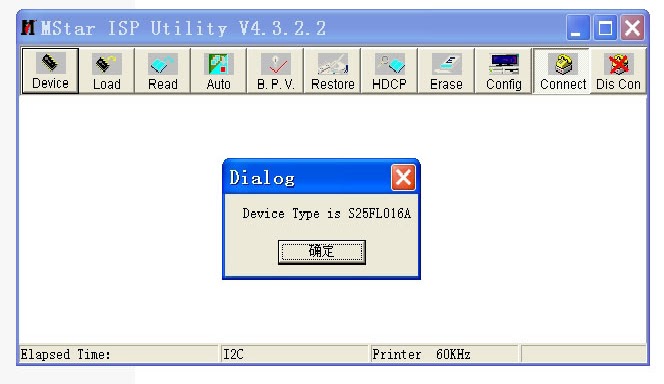
  • If cable connect is ok, you can get the follow picture. If failure please double check the cable connect and try again.
  • Click 'Read' icon.
  • Click the follow Icon of Read.
  • To Select the update software for Dynex.
  • Select Open Icon. Then will appear the follow picture.
  • Click the Icon of Auto
  • Then will appear the follow picture.
  • Click the Icon of Run, the software will be updated to Dynex.  It will take about 10 minutes.
  • If update software is finished and OK, It will appear PASS. If error please retry.
  • Disconnect the Dynex from Power Socket, until the Power LED no light, then reconnect the Dynex to Power Socket and Power on the TV.
SERVICE MODE
  1. Press “INPUT”, “2”, “5”, ”8” and “0” in turn to enter level-one factory menu;
  2. Press “CH+” and “CH-” to move the cursor to the adjustment page of the level-one factory menu then press “OK” to enter;
  3. Press “CH+” and “CH-” to move the cursor up and down;
  4. When the cursor move to a certain adjust item, press “ VOL+” and “VOL –“ to adjust value;
  5. Press “MENU” to exit to the level-one factory menu;
  6. Press “EXIT” to exit the factory menu.
  7. After exit the factory menu, press “SLEEP” to enter the factory menu again as long as power on.
  8. “Power on mode” item of “Otherseting” menu: on= turn on; off =standby; memory=memory function of turn on.

Tuesday, 19 March 2019

INSIGNIA NS-LCD37HD-09 _ XOCECO - LC37HV41 – TROUBLESHOOTING CHART - MAIN POWER SUPPLY [SMPS] SCHEMATIC (CIRCUIT DIAGRAM)

INSIGNIA NS-LCD37HD-09 _ XOCECO - LC37HV41 – TROUBLESHOOTING CHART - Main Power Supply [SMPS] Schematic (Circuit Diagram)


Before servicing, check to find the possible cause of the fault according to the table below.

Picture is out of focus or jumping
* Bad status in signal receiving
*  Poor signal
*  Check if there are failures with the electrical connector or the antenna.
*  Check if the antenna is properly connected.

Fringe in picture
* Check if the antenna is correctly oriented.
*  Maybe there is electric wave reflected from hilltop or building.

Picture is interfered by stripe shaped bright spots 
* Possibly due to interference from auto-mobile, train, high voltage transmission line, neon lamp etc.
*  Maybe there is interference between antenna and power supply line. Please try to separate them in a longer distance.
*  Maybe the shielded-layer of signal wire is not connected properly to the connector.

There appear streaks or light colour on the screen
Check if interfered by other equipment and if interfered possibly by the equipment like transmitting antenna, non-professional radio station and cellular phone.

Unable to switch the power on
Check to see if the power plug has been inserted properly into the socket.

No picture and sound
* Check to see if the power supply of liquid crystal TV has been switched on. (As can be indicated by the red LED at the front of the TV set)
*  See if it’s receiving the signal that is transmitted from other source than the station
*  Check if it’s connected to the wrong terminal or if the input mode is correct.
*  Check if the signal cable connection between video frequency source and the liquid crystal TV set is correct.

Deterioration of colour phase or colour tone
Check if all the picture set-ups have been corrected.

Screen position or size is not proper
Check is the screen position and size is correctly set up.

Picture is twisted and deformed
Check to see if the picture-frame ratio is properly set up.

Picture colour changed or colourless
Check the “Component” or “RGB” settings of the liquid crystal TV set and make proper adjustment according to the signal types.

Picture too bright and there is distortion in the brightest area. 
* Check if the contrast setting is too high.
*  Possibly the output quality of DVD broadcaster is set too high.
*  It maybe also due to improper terminal connection of the video frequency signal in a certain position of the system.

Picture is whitish or too bright in the darkest area of the picture
* Check if the setting for the brightness is too high
*  Possibly the brightness grade ofDVD player (broadcaster) is set too high.

No picture or signal produced from the display if “XXX in search” appears.
 * Check if the cable is disconnected.
*  Check if it’s connected to the proper terminal or if the input mode is correct.
There appears an indication -                (outside the receivable scope)
* Check if the TV set can receive input signal. The signal is not correctly identified and VGA format is beyond the specified scope.

Remote control cannot work properly
* Check if the batteries are installed in the reverse order.
*  Check if the battery is effective.
*  Check the distance or angle from the monitor.
*  Check if there is any obstruct between the remote control and the TV set.
*  Check if the remote control signal- receiving window is exposed to strong fluorescence.

No picture and sound, but only hash.
Check if the antenna cable is correctly connected, or if it has received the video signal correctly. 

Blur picture
* Check if the antenna cable is correctly connected.
* Of if it has received the right video signal.

No sound
* Check if the “mute” audio frequency setting is selected.
*  Check if the sound volume is set to minimum.
*  Make sure the earphone is not connected.
*  Check if the cable connection is loose.

When playing VHS picture search tape, there are lines at the top or bottom of the picture.
When being played or in pause VHS picture search tape sometimes can’t provide stable picture, which may lead to incorrect display of the liquid crystal TV, In this case press “auto” key on the remote control so as to enable the
liquid crystal TV set to recheck the signal and then to display correct picture signal
NO RASTER
RASTER OK, BUT NO PICTURE
PICTURE OK, BUT NO SOUND [TV-INPUT]
PICTURE OK, BUT NO SOUND [CHANNEL EXCEPT TV]
SMPS SCHEMATIC
CLICK ON PICTURES TO ZOOM IN

Wednesday, 13 March 2019

XOCECO - INSIGNIA 19KK44 SERVICE MODE POWER SUPPLY AND INVERTER CIRCUIT

XOCECO - INSIGNIA 19KK44 SERVICE MODE POWER SUPPLY AND INVERTER CIRCUIT


LCD TV SERVICE MODE POWER SUPPLY AND INVERTER CIRCUIT 


SERVICE MODE
a) First press key “INPUT”, then press number keys “2, 5, 8, 0” in turn to enter initial class factory menu;
b) Press keys “CH+” and“CH-” , move cursor to each adjustment page of initial class factory menu, then press key“ENTER” to enter into adjustment menu of each adjustment page;
c) Press keys “CH+” and“CH-” to move cursor upwards or downwards within any adjustment page;
d) Move cursor to any adjustment item, press key“VOL-” or“VOL+” to adjust it;
e) Press key“MENU” to return to initial menu from any page of adjustment menu;
f) Press key“EXIT” to exit factory menu at any time;“EXIT”
g) Set item “Aging Mode” as “On” to enter into factory-aging mode;
White balance adjustment
Pre-adjustment
The set should be working for over 30 minutes before white balance adjustment so that it can be in a stable state. Use white balance apparatus CA210 and change to BBY channel to adjust white balance; Only need to adjust chromaticity coordinates when color temperature is 10000K (namely “COOL”) for the unit. To meet testing requirements of BBY when color temperature is 8000K or 6500K, make sure chromaticity coordinates of bright scale is X=280
± 5 Y=288 ± 5, chromaticity coordinates of dark scale is X=280± 8 Y=288± 8; Manual adjustment of both groups of white balance datum YPbPr white balance adjustment
ADC correction:
Input signal with format of 720P/60 Hz and content of SMPTE color bar plus gray scale (Timing of VG848 is 976, PAT is 984 ); enter into page “Auto Color” of factory menu, set item “Source” as “VG848”, set item “Test Pattern” as “SMPTE Color Bar”, then select item “Start to do auto color” , press key “Enter”, the picture will twinkle for a moment and then return to normal, a prompt of “Auto Color Successful” will be displayed, that is, ADC correction is completed; press key “Menu” to return to the superior menu;
White balance adjustment:
The set should be working for over 30 minutes before white balance adjustment so that it can be in a stable state. Use apparatus CA210 and change to CH2 channel, input signal with format of 720P/60 Hz and content of 16 gray-scale, enter into page “White Balance/Color Temp” of factory menu, fix item “Green Gain”, adjust items “Red Gain
Blue Gain” to set chromaticity coordinates of the 13th scale as 280 288 ;fix item “Green Offset”, adjust items “Red Offset Blue Offset” to set chromaticity coordinates of the 4th scale as 280 288 . Repeat adjust items “Red Gain Blue Gain” and “Red Offset Blue Offset” until chromaticity coordinates of both gray scales are 280 288 , the error of dark scale should be within ± 8 and the error of bright scale should be within ± 5; then press key  “Menu” to return to the superior menu.  Check if color temperature of “NORMAL” and “WARM” is normal (the error of dark scale should be within ± 8, the error of bright scale should be within ± 5); otherwise adjust item “Color Temp NORMAL” and “Color Temp WARM” to meet requirements and then save them. Note: Should not need to adjust white balance if panel has good coincidence indicator.
VGA white balance alignment
ADC correction:
Input signal with format of 640
× 480/60 Hz and content of 16 gray-scale (Timing of VG848 is 1, PAT is 921 ); enter into “Auto Color” page of factory menu, set item “Source” as “VG848”, then select item “Start to do auto color” and press key “Enter”, the picture will twinkle for a moment and then return to normal, a prompt of “Auto Color Successful” will be displayed, that is, ADC correction is completed; press key “Menu” to return to the superior menu;
 White balance adjustment:
 The set should be working for over 30 minutes before white balance adjustment so that it can be in a stable state. Use apparatus CA210 and change to CH2 channel, input signal with format of 640× 480/60 Hz and content of 16 gray-scale, enter into page “White Balance/Color Temp” of factory menu, fix item “Green Gain”, adjust items “Red Gain Blue Gain” to set chromaticity coordinates of the 13th scale as 280 288 ;fix item “Green Offset”, adjust items “Red Offset Blue Offset” to set chromaticity coordinates of the 4th scale as 280 288 . Repeat adjust items “Red Gain Blue Gain” and “Red Offset Blue Offset” until chromaticity coordinates of both gray scales are 280 288 , the error of dark scale should be within ± 8 and the error of bright scale should be within ± 5; then press key “Menu” to return to the superior menu. Check if color temperature of “NORMAL” and “WARM” is normal (the error of dark scale should be within ± 8, the error of bright scale should be within ± 5); otherwise adjust item “Color Temp NORMAL” and “Color Temp WARM” to meet requirements and then save them.

Note: Should not need to adjust white balance if panel has good coincidence indicator. Auto white balance adjustment
Pre-ADC correction
Enter into factory menu, set item “InputSource” as “Component1\Component2”, input signal with format of 720P/60 Hz and content of SMPTE color bar plus gray scale (Timing of VG848 is 976 PAT is 984), then enter into page “Auto Color”, set item “Source” as “VG848”, set item “Test Pattern” as “SMPTE Color Bar”, then select item “Start to do auto color”, press key “Enter”, the picture will twinkle for a moment and then return to normal, a prompt of “Auto Color Successful” will be displayed, that is, ADC correction is completed; press key “Menu” to return to the superior menu; then set item “InputSource” as “VGA”, input signal with format of 640× 480/60 Hz and content of 16 gray-scale(Timing of VG848 is 1, PAT is 921 ), follow above steps to complete ADC correction.
Auto white balance adjustment
The set should be working for over 30 minutes before white balance adjustment so that it can be in a stable state. Connect CA210 to USB port of a compute with a data line, connect VG848 and TV to COM port or virtual COM port of a computer respectively (default connection is that VG848 to COM5 and TV to COM1; enter into administrator window with password “xoceco” to change the default connection if necessary and then save it); be sure to output VG848 signal to AV2
YPbPr2 VGA HDMI3 ports of TV. Open file “White_Balance.exe”, load config file “AdjustConfig.txt”, then connect CA210 VG848 TV respectively according to the indication of interface prompt .(note: set probe as “0-CAL”before connecting to CA210, then press item “connect to CA210”, set probe as “MEAS” when a prompt “CA-210 connection and correction are normal” is displayed on the left-bottom side; default channel for CA210 is CH02 BBY; enter into administrator window with password “xoceco” to change the default setting if apparatus is different and then save it.) Press item “auto white balance adjustment”, auto-adjustment will be completed when a prompt “adjusting successfully” is displayed.
User menu setup before leaving factory
Enter into factory menu, select item “Reset to default”, the machine will preset items of user menu automatically before leaving factory. Be sure to do this step after alignment in the factory.
SMPS POWER SUPPLY CIRCUIT 

BACK LIGHT INVERTER CIRCUIT 

CLICK ON THE IMAGES TO ZOOM IN

Monday, 11 March 2019

SAMSUNG UN32D5500RF - UN40D5500RF TROUBLE SHOOTING AND SERVICE MODE

SAMSUNG UN32D5500RF - UN40D5500RF TROUBLE SHOOTING AND SERVICE MODE


SAMSUNG UN32D5500RF - UN40D5500RF 

LED TV

TROUBLE SHOOTING AND SERVICE MODE 


Troubleshooting
Previous check
1. Check the various cable connections first.
Check to see if there is a burnt or damaged cable.
Check to see if there is a disconnected or loose cable connection.
Check to see if the cables are connected according to the connection diagram.
2. Check the power input to the Main Board.
No Power
Symptom
The LEDs on the front panel do not work when connecting the power cord.
The SMPS relay does not work when connecting the power cord.
The units appears to be dead.
Check points
The IP relay or the LEDs on the front panel does not work when connecting the power cord if the cables are improperly connected or the Main Board or SMPS is not functioning.
In this case, check the following:
Check the internal cable connection status inside the unit.
Check the fuses of each part.
Check the output voltage of SMPS.
Replace the Main Board.
No Video_Analog PC signal
Symptom
Audio is normal but no picture is displayed on the screen.
Check points
Check the PC source
Check the Arsenal, Check the Chelsea.
This may happen when the LVDS cable connecting the Main Board and the Panel is disconnected.
No video_HDMI1, 2, 3, 4 - Digital signal
Symptom
Audio is normal but no picture is displayed on the screen.
Check points
Check the HDMI source.
Check the HDMI switch, Check the Chelsea.
This may happen when the LVDS cable connecting the Main Board and the Panel is disconnected.
No Video_Tuner - CVBS
Symptom
Audio is normal but no picture is displayed on the screen.
Check points
Check the Tuner CVBS source.
Check the Tuner, Check the Chelsea.
This may happen when the LVDS cable connecting the Main Board and the Panel is disconnected.
No Video_Tuner DTV
Symptom
- Audio is normal but no picture is displayed on the screen.
Check points
Check the DTV source.
Check the Tuner, Check the Chelsea.
This may happen when the LVDS cable connecting the Main Board and the Panel is disconnected.
No Video_Video CVBS
Symptom
Audio is normal but no picture is displayed on the screen.
Check points
Check the Video CVBS source
Check the Chelsea.
This may happen when the LVDS cable connecting the Main Board and the Panel is disconnected.
No Video_Component
Symptom
- Audio is normal but no picture is displayed on the screen.
Check points
Check the Component source
Check the chelsea.
This may happen when the LVDS cable connecting the Main Board and the Panel is disconnected.
No Sound
Symptom
Video is normal but there is no sound..
Check points
When the speaker connectors are disconnected or damaged.
When the sound processing part of the Main Board is not functioning.
Speaker defect..
Factory Mode Adjustments
Entering Factory Mode
If you do not have Factory remote - control
Power OFF >  MUTE > 1 > 8 > 2 > Power ON
If you do not have Factory remote - control
INFO >  Factory
Method of Color Calibration (AV)
1) Apply the NTSC Lattice (N0. 3) pattern signal to the AV IN 1 port.
2) Press the Source key to switch to “AV1” mode.
3) Enter Service mode.
4) Select the “ADC” menu.
5) Select the “AV Calibration” menu.
6) In “AV Calibration Off” status, press the “ > ” key to perform Calibration.
7) When Calibration is complete, it returns to the high-level menu.
8) You can see the change of the “AV Calibration” status from Failure to Success.
Method of Color Calibration (Component)
1) Apply the 720p Lattice (N0. 6) pattern signal to the Component IN 1 port.
2) Press the Source key to switch to “Component1” mode.
3) Enter Service mode.
4) Select the “ADC” menu.
5) Select the “Comp Calibration” menu.
6) In “Comp Calibration Off” status, press the “ >” key to perform Calibration.
7) When Calibration is complete, it returns to the high-level menu.
8) You can see the change of the “Comp Calibration” status from Failure to Success.
Method of Color Calibration (PC)
1) Apply the VESA XGA Lattice (N0. 21) pattern signal to the PC IN port.
2) Press the Source key to switch to “PC” mode.
3) Enter Service mode.
4) Select the “ADC” menu.
5) Select the “PC Calibration” menu.
6) In “PC Calibration Off” status, press the “ > ” key to perform Calibration.
7) When Calibration is complete, it returns to the high-level menu.
8) You can see the change of the “PC Calibration” status from Failure to Success.
Method of Color Calibration (HDMI)
1) Apply the 720p Lattice (N0. 6) pattern signal to the HDMI1/DVI IN port.
2) Press the Source key to switch to “HDMI1” mode.
3) Enter Service mode.
4) Select the “ADC” menu.
5) Select the “HDMI Calibration” menu.
6) In “HDMI Calibration Off” status, press the “ > ” key to perform Calibration.
7) When Calibration is complete, it returns to the high-level menu.
8) You can see the change of the “HDMI Calibration” status from Failure to Success.
Software Upgrade
Software Upgrade can be performed by downloading the latest firmware from samsung.com to a USB memory device.
Current Version - the software already installed in the TV.
Note : Software is represented as ‘Year/Month/Day_Version’.
How to check the SW version
Use the main menu
1. Click the “menu” key in remote controler.
2. Select Support menu.
3. Locate the menu cursor “Software Upgrade” menu.
4. Click the “info” key.
5. Check the Main SW and Micom version.
Use the factory mode
Access the factory mode
How to Upgade SW and Micom
Insert a USB drive containing the firmware upgrade downloaded from samsung.com into the TV.
Please be careful to not disconnect the power or remove the USB drive while upgrades are being applied. The TV will turn off and turn on automatically after completing the firmware upgrade. Please check the firmware version after the upgrades are complete (the new version will have a higher number than the older version). When software is upgraded, video and audio settings you have When software is upgraded, video and audio settings you have you write down your settings so that you can easily reset them after the upgrade.
Main SW upgrade
1. Store the sw program named “T-MST5IBRC” in USB memory stick.
Connect the USB.
Connect TV and online line.
2. Click the MENU key in remote controler.
3. Select Support menu.
Locate the menu cursor Software Upgrade menu.
4. Click the ENTER key.
You can upgrade By USB or Online.
5. Click the ENTER key.
Wait for upgrade complete and check the SW version.
Sub micom upgrade
You can upgarde sub micom in factory mode without DDC program.
But it take long time about 5 minuites.
1. Access the fatory mode.
 Select the SVC menu and locate the cursor MICOM UPGRADE menu
2. Click the ENTER key.
Click the right key.
Wait for upgrade complete and check the Micom version.
Power supply connector voltages

CN201 (to Powr Board)
1
B5V
2
SW_POWER
3
B5V
4
A5V
5
GND
6
GND
7
B12VS
8
GND
9
B12VS
10
SW_INVERTER
11
B13V
12
NC
13
B13V
14
PWM_DIMM