REPAIRING AND NOT THROWING AWAY

Richtige Fernseher haben Röhren!

Richtige Fernseher haben Röhren!

In Brief: On this site you will find pictures and technical information about Service Modes, Circuit Diagrams, Firmware Update procedure, Disassemble procedure, Universal remote control set-up codes, Troubleshooting and more....

If you go into the profession, you will obtain or have access to a variety of tech tips databases HERE IT IS Master Electronics Repair !.

These are an excellent investment where the saying: 'time-is-money' rules. However, to learn, you need to develop a general troubleshooting approach - a logical, methodical, method of narrowing down the problem. A tech tip database might suggest: 'Replace C536' for a particular symptom. This is good advice for a specific problem on one model. However, what you really want to understand is why C536 was the cause and how to pinpoint the culprit in general even if you don't have a service manual or schematic and your tech tip database doesn't have an entry for your sick TV or VCR.

While schematics are nice, you won't always have them or be able to justify the purchase for a one-of repair. Therefore, in many cases, some reverse engineering will be necessary. The time will be well spent since even if you don't see another instance of the same model in your entire lifetime, you will have learned something in the process that can be applied to other equipment problems.
As always, when you get stuck, checking out a tech-tips database may quickly identify your problem and solution.In that case, you can greatly simplify your troubleshooting or at least confirm a diagnosis before ordering parts.

Happy repairing!
Today, the West is headed for the abyss. For the ultimate fate of our disposable society is for that society itself to be disposed of. And this will happen sooner, rather than later.

How to use the site:

- If you landed here via any Search Engine, you will get what you searched for and you can search more using the search this blog feature provided by Google. You can visit more posts scrolling the left blog archive of all posts of the month/year,
or you can click on the main photo-page to start from the main page. Doing so it starts from the most recent post to the older post simple clicking on the Older Post button on the bottom of each page after reading , post after post.

You can even visit all posts, time to time, when reaching the bottom end of each page and click on the Older Post button.

- If you arrived here at the main page via bookmark you can visit all the site scrolling the left blog archive of all posts of the month/year pointing were you want , or more simple You can even visit all blog posts, from newer to older, clicking at the end of each bottom page on the Older Post button.
So you can see all the blog/site content surfing all pages in it.

- The search this blog feature provided by Google is a real search engine. If you're pointing particular things it will search IT for you; or you can place a brand name in the search query at your choice and visit all results page by page. It's useful since the content of the site is very large.

Note that if you don't find what you searched for, try it after a period of time; the site is a never ending job !

..............The bitterness of poor quality is remembered long after the sweetness of todays funny gadgets low price has faded from memory........ . . . . . .....
Don't forget the past, the end of the world is upon us! Pretty soon it will all turn to dust!

©2010, 2011, 2012, 2013, 2014 Frank Sharp - You do not have permission to copy photos and words from this blog, and any content may be never used it for auctions or commercial purposes, however feel free to post anything you see here with a courtesy link back, btw a link to the original post here , is mandatory.
All posts are presented here for informative, historical and educative purposes as applicable within fair use. NOTHING HERE IS FOR SALE !

Showing posts with label KENWOOD. Show all posts

Tuesday, 18 August 2020

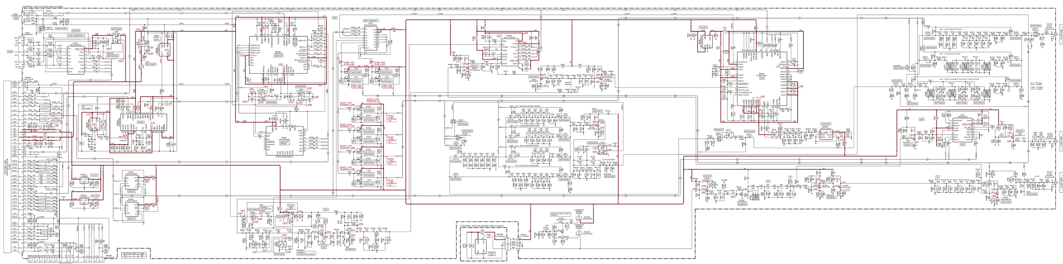
TS590S KENWOOD HF 50MHZ ALL MODE TRANSCEIVER CIRCUIT DESCRIPTION AND SCHEMATIC HOW TO DISASSEMBLE

TS590S Kenwood HF 50MHz ALL MODE TRANSCEIVER How to disassemble, circuit description and schematic


Disassemble procedure - Removing the torque changeover lever
Insert the tip of a flat-head screwdriver (or other implement) under the tab of the torque changeover lever, and then lift the tab using the tip of the flat-head screwdriver. (1)
Caution: Be careful not to damage the panel when lifting.
Turn the lever section of the torque changeover lever to the right, as in the position described in step 1. (2)
Lift the torque changeover lever and remove it from the panel. (3)
Mounting the torque changeover lever
Insert the torque changeover lever by aligning the three tabs of the panel. (1)
Slightly turn the lever section of the torque changeover lever to the left (3) while pressing the surface near the tab at the lower right of the torque changeover lever (2).
Caution: Confirm that the torque changeover lever is caught by the lower right tab of the panel.
Turn the lever section of the torque changeover lever to the left (4) while pressing the surface near the tab at the upper right of the torque changeover lever (5), and then mount it onto the panel.
Procedures when Replacing the Diode (1SR139-400) for hand mounting
When replacing the diode (D304: 1SR139-400) used by the Control unit (A/3) (PCB number: J79-0279-09), cut the leg of a new diode.
Bend the leg of the diode as shown in the figure.
Solder the diode between Q61 (Collector) and the solder pad (Base) of the Control unit (A/3), as shown in the figure.
Confirm the direction of the cathode band when installing the diode.
Install the diode so that it is positioned on the dotted line.
 Install the diode so that its height from the surface of the PCB is 4mm (0.16 inches) or less (Height of rubber sheet (G11-4536-04): 4mm (0.16 inches)).
Precautions for Reassembly
Perform the following steps when assembling the bottom side of the transceiver.
1. Separate the two coaxial cables (E37-1495-05, E37-1496-05) as shown in the figure.
2. Push the two flat cables (E37-1491-05, E37-1492-05) into the gap of the chassis so they do not come into contact with the cabinet.
Caution for Replacing the LED (B30-2322-05, B30-2323-05)
When replacing the “B30-2322-05” or “B30-2323-05” LED used by the Display unit (A/6), order and replace the LED for service into which the rank is divided according to brightness, according to the following procedures, so that the brightness of the LED backlight remains uniform after replacing the LED.
Confirm whether the “A” or “Z” stamp is pushed on the foil side of Display unit (A/6).
Order and replace the LED for service as shown in the following table according to whether stamp “A” or “Z” exists or not.
Frequency Configuration
Figure shows the frequency configuration of this transceiver.
While transmitting, FM mode operates in a double conversion and other modes (AM, SSB, CW, FSK) operate in a triple conversion.
While receiving, the first IF operates in 73.095MHz triple conversion. In modes other than FM, the third IF is 24kHz, and the IF signal is converted by an A/D converter and input into DSP. The FM mode is detected in the FM IC, and the audio signal is converted by an A/D converter and input into the DSP. Under the following conditions, the first IF operates its reception in 11.374MHz double conversion.
1) Modes other than AM or FM
2) Amateur band within the 1.8/3.5/7/14/21MHz bands
3) DSP filter’s bandwidth is 2.7kHz or lower.
Reference Signal Generator
The reference frequency (fstd), which is used to control the individual LO frequencies, oscillates at 15.6MHz in a crystal oscillation circuit (X502, Q501). This 15.6MHz signal passes through a buffer (Q502) and is doubled in a multiplier (Q503) to generate a 31.2MHz signal. The 31.2MHz signal is used as a reference signal for LO3 (the third local oscillator) DDS (IC601). The 31.2MHz signal is doubled in multipliers (Q504, Q505) to generate a 62.4MHz signal. The 62.4MHz signal is used as a reference signal for LO1 (the first local oscillator) PLL (IC801).  The SO-3 (TCXO unit: 15.6MHz) is configured as an option in this transceiver, so that you can replace the crystal oscillation circuit (X502, Q501) with the SO-3. When using the SO-3, remove the CN903 and CN904 short jumper wires in order to stop the operation of the crystal oscillation circuit (X502, Q501).
LO1/ LO2/ LO3
LO1 (the first local oscillator)
The VCO (Q806) oscillates at 196.8MHz. Only the double frequency component, 393.6MHz, of this VCO’s oscillation output is extracted and input into PLL (IC801) pin 6.
This input signal is divided into 1/N within the PLL. Also, the 62.4MHz signal (15.6MHz reference frequency x 4) is input into PLL pin 8 and divided into 1/R within the PLL. By a phase comparator in the PLL, the frequency divided into 1/N and the frequency divided into 1/R are compared, and then the frequency is locked. The comparison frequency (fø) at this time is 120kHz when transmitting FM, and 2.4MHz otherwise.
393.6MHz signal locked by PLL (IC801) would be used as reference by DDS (IC803). The output signal from DDS (IC803) is 12.495MHz to 32.195MHz when RX-1 path is selected, amplified at the broad band amplifier (IC804), and then goes through BPF and is output as LO1. When
RX-2 path is selected or when transmitting, 36.5625MHz to 66.5475MHz is output, amplified by the broad band amplifier (IC804), and then doubled in the multiplier (D652), goes through BPF, and is output as 73.120MHz to 133.095MHz LO1
LO2 (the second local oscillator)
The reference oscillating circuit’s output signal 15.6MHz signal passes through a buffer (Q502) and is doubled in a multiplier (Q503) to generate a 31.2MHz signal. The 31.2MHz signal is also used as the DDS (IC601)’s reference frequency, and therefore its resistance is divided. Then, the 31.2MHz signal is doubled in multipliers (Q504, Q505) to generate a 62.4MHz signal.  The 62.4MHz signal’s high harmonic is cut in the BPF and the signal is amplified in the amplifier (Q506) to generate LO2. If IFB is selected, the diode switch (D501) cuts the LO2 output.
LO3 (the third local oscillator)
The LO3 used in the modulator and the detector is generated in the DDS (IC601). The DDS output signal passes through the buffer (Q602) and LPF to generate LO3.
Receiver Circuit
In an amateur frequency band or mode that requires antiproximate interference, the receive signal passes through the double conversion RX-1 path, and in other frequency bands and modes, it passes through the triple conversion RX-2 path.
From the antenna terminal to the preamplifier (Q236)
The receive signal from the antenna terminals (ANT1/ANT2) passes through the antenna changeover relay (K44) in the Final unit (X45-391 A/2), the antenna tuner’s IN/THROUGH changeover relay (K45), the transmission/reception changeover relay (K46), and an image filter, and is sent from CN51 to the TX-RX unit (X57-785 A/2)’s CN100 (RAT) through a co-axial cable.
The signal input into the TX-RX unit passes through the RX ANT changeover relay (K101) and enters the attenuator circuit (ATT) which is approximately 12dB. This can be switched to approximately 20dB by removing the CN101 short jumper. Then, the signal passes through LPF for IF trap, the surge absorption limiter, and the BC band attenuating circuit (removes 30kHz to 1.705MHz), and enters the BPF. In the BC band attenuating circuit, in order to avoid interference by high-output broadcasting stations, 11.7MHz and 15.5MHz trap circuit is inserted into E type only.
The BPF divides in the range as shown in table 3. The BC band’s BPF includes ATT for avoiding cross-modulation by medium wave band high-output station (ATT ON: CN102=open, CN103=short, ATT OFF: CN102=short, CN103=open). The transmit signal also passes through the BPF when transmitting. The preamplifier (Q236) receives the signal passed through the BPF. In this model, it is an emitter grounding circuit which uses a bipolar transistor. Q239 switches the emitter’s returning amount to adjust the gain. Approximately 20dB is gained in 21.5 to 60MHz and approximately 12dB in other frequencies. The preamplifier circuit can be passed by turning off the PRE display with the preamplifier key .
From the preamplifier (Q236) to the second IF frequency (10.695MHz/11.374MHz)
The signal from the preamplifier (Q236) output to the second IF amplifier 1 (Q451) is spread into 2 paths: RX-1 and RX-2, depending on the frequency band (refer to table)  The RX-1 path is selected when the “L” signal is added to Q273, and the RX-2 path is selected if the “H” signal is added.
The RX-1 path signal passes through the LPF for IF trap, is integrated with LO1 (12.495 to 32.195MHz) in the quadbalance first mixer (Q263 to Q266), and is then converted to the first IF (11.374MHz). The first IF signal passes through the 2-pole MCF (XF301) and enters the second IF amplifier 1 (Q451). The RX-2 path signal passes through the LPF for IF trap, is integrated with LO1 (73.120 to 133.095MHz) in the quadbalance first mixer (Q321 to Q324), and is then converted to the first IF (73.095MHz). The first IF signal passes through the 2-pole MCF (XF371), and by the trans-feedback type NFB (negative feedback) first IF amplifier (Q391), is amplified by approximately 12dB. The amplified signal is mixed with LO2 (62.4MHz) in the second mixer (D422, D423), converted to the second IF (10.695MHz), and then enters the second IF amplifier 1 (Q451). The second mixer is a passive type that uses a diode, and is a bilateral circuit that converts both receive signal's frequency at the time of reception and transmission signal's frequency at the time of transmission.  The second IF signal that passed through the RX-1 or RX-2 path is amplified by approximately 13dB in the second IF amplifier 1 (Q451), and is then divided into 2 paths: the NB (noise blanker) circuit and the blanking circuit (D461 to D464). Blanking is carried out by D461 to D464.  Then, the second IF signal passes through the IF filter.
One of 5 filters is selected, depending on the frequency and the mode (refer to table).
The second IF signal that passed through the IF filter enters the AGC circuit (diode ATT circuit: D522 to D524).  The AGC voltage output from the DSP is added to D522 to D524, the change of AGC voltage changes the current on the pin diode and controls the attenuation of the signal passing through. And, the second IF amplifier 2 (Q541) and the second IF amplifier 3 (Q521, Q522) altogether amplify by the total of approximately 32dB, and the signal passes through the simplified diode ATT circuit (D525). The voltage determined in the adjustment mode is added to D525, and adjusts the difference of the total gains of the RX-1 and RX-2 paths.
Kenwood TS590s Schematic

Saturday, 1 August 2020

KENWOOD KDC-2023, KDC-2024SA CD RECEIVER FULL SCHEMATIC DIAGRAM, SYSTEM CONTROL IC PIN FUNCTION DETAILS KNOWLEDGE

 Kenwood CD receiver KDC-2023, KDC-2024SA/SG/SYA/SYG, KDC-2094YA/YG, KDC-222/S, KDC-3023

For continued safety, replace safety critical components only with manufacturer's recommended parts.  To reduce the risk of electric shock, leakage-current or resistance measurements shall be carried out (exposed parts are acceptably insulated from the supply circuit) before the appliance is returned to the customer.
 DC voltages are measured with a high impedance voltmeter. Values may vary slightly due to variations between individual instruments 
and units.

CD mechanism extension cord : WO5-0618-00


CD player schematic.


System microcontroller Destination type list.

Kenwood KDC-2023, 2024A/SG/SYA/SYG, 2094YA/YG, 222/S,3023 MICROCOMPUTER'S TERMINAL DESCRIPTION - MECHANISM MICROCOMPUTER MN6627771KP (X32 : IC2)

Kenwood 2024A/SG/SYA/SYG, 2094YA/YG, 222/S,3023 - MICROCOMPUTER'S TERMINAL DESCRIPTION

Kenwood KDC-2023, 2024A/SG/SYA/SYG, 2094YA/YG, 222/S,3023 COMPONENTS DESCRIPTION

Wednesday, 15 January 2020

KENWOOD DVR6200, KENWOOD KSW6200 DVD/AV RECEIVER - [DVT6200] SCHEMATIC

DVD/AV receiver - Kenwood DVR6200, Kenwood KSW6200 [DVT6200] Schematic


The DC voltage is an actual reading measured with a high impedance type voltmeter with no signal input. The measurement value may vary depending on the measuring instruments used or on the product.
System configuration:
System: DVT6200
Main unit: DVR6200
Speaker: KSW6200
How to open the tray, if it does not come out  [when there is no power]
Insert a flat screwdriver in the drawing through the hole on the loading chassis bottom, and pull the lever down.

Pull out the tray frontward by hand when it comes just out.
Caution on condensation
Condensation (of dew) may occur inside the unit when there is a great difference in temperature between this unit and the outside. This unit may not function properly if condensation occurs. In this case, leave the unit for a few hours and restart the operation after the condensation has dried up.
When this unit is carried from one place to another across a large difference in temperature, when the humidity in the room where this unit is installed increases, etc
Schematic
Exploded View
SMPS (PSP-2571)
Standby LED Blinking / Flashing: check and replace D21 1N5819 [at SMPS]
No + 5V:  Check and replace 5M0165R at SMPS

Wednesday, 10 April 2019

KENWOOD DPX502 - DPX502U - DPX502UY - DPX-MP5100U KENWOOD CAR AUDIO - – CD-USB RECEIVER – TEST MODE – AUDIO INITIALIZATION – CLEARING SECURITY CODE

Kenwood Car audio - Kenwood DPX502 - DPX502U - DPX502UY - DPX-MP5100U – CD-USB RECEIVER – Test mode – Audio initialization – Clearing security code

TEST MODE
How to enter the test mode
Press and hold the [1] and [3] keys and reset. (While “– – – –” is being displayed, power can be ON for 30 minutes.)
How to clear the test mode
Reset, momentary power down, Acc OFF, Power OFF, detach the panel.
Test mode default condition
# Source is STANDBY.
# Display lights are all turned on.
# The volume is at 30 (-10dB).
# LOUD is OFF.
# CRSC is off regardless of the availability of switching function.
# SYSTEM EQ is NATURAL ( = FLAT).
# BEEP should always function when the key is pressed briefly .
# AUX is ON.
Specification of the test mode for tuner source
The frequency of 98.3MHz is received when the [4] key is pressed in the TUNER FM mode
Specification of FST soft mute adjustment mode
1. Receive the TUNER FM mode in the VOLUME 30 and LOUD OFF condition.
2. Press and hold the [PLAY] key for 2 seconds to enter the FST soft mute adjustment mode.
3. In the adjustment mode, the following display is shown.
Adjust the mute between 0 (18dBu) and F (36dBu) with the [FM] / [AM] keys.
(Display) SMD–x_ _ _ (Adjustment value, 0-F is displayed in “x”).
4. When the adjustment is “OK”, press and hold the [PLAY ] key for 2 seconds again to write the adjustment value in the E2PROM, and after the successful writing-in the “EP_WRITE” is displayed.
5. Press the [ PLAY ] key briefly to exit from the FST soft mute adjustment mode.
Special display in tuner mode
Error is found in front-end, etc. if indications below are displayed while in tuner mode.
# “TNE2P_NG” : E2PROM (in front-end: A500 of X34-) values are still default (not determined)
“TNCON_NG” : Cannot communicate with the front-end.
RDS/RBDS automatic measurement
When it is confirmed that the PS data has been received and that the content of the PS is “RDS_TEST”, force to OFF the P-CON terminal. ( The symbol, “_” indicates the blank. )
Make this as the process dedicated for the test mode.
P-CON is recovered by Power OFF> ON.
K3I forced switching
Every time when [6] key is pressed in tuner FM mode, switched in the following order: AUTO > Forced WIDE > Forced MIDDLE > Forced NARROW > AUTO. Default status is AUTO, and displayed as shown below.
# AUTO: FM1_98.1A , Forced WIDE: FM1_98.1W
# Forced MIDDLE: FM1_98.1M . Forced NARROW: FM1_98.1N
CD source test mode specification
# Display mode default setting shall be P-TIME.
# Jumps to the following tracks by pressing the [NEXT ] key.
No.9 > No.15 > No.10 > No.11 > No.12 > No.13 > No.22 >  No.14 > No.9 (recursive)
Note that when playing a CD-DA disc and MP3 / WMA/ AAC / WAV discs with 8 files or less, the disc is played from the 1 track in the normal order.
# Pressing the [ PREVIOUS ] key goes back by 1 track from the track being played.
# When playing an MP3 / WMA / AAC/WAV disc, display the file format before starting to play each file.
( “MP3”, “WMA”, “AAC”, “WAV” )
# While in CD source, press the [1] key briefly to jump to No.28.
# While in CD source, press the [2] key briefly to jump to No.14.
# While in CD source, press the [3] key briefly to display CD mechanism model name and the version.
Press the [3] key briefly again to return to the normal display. (Time code display)
While in CD source, press the [6] key briefly to jump to No.15. At this time, the volume value is set to 25 (2V PRE).
AUDIO adjust mode
# Press the [AUD] key and enter the audio adjustment mode.
# Press the remote control [∗] key and [AUD] key to enter the audio adjustment mode.
# Both AUDIO FUNCTION MODE and SETUP MODE adjustment items are included.
# By pressing [AUD] and [FM] key briefly, switch the item to be adjusted in the following order. (Only in forward rotation)
The default item shall be Fader, and then the item is forwarded in the following order: Balance  > Bass Level > Middle Level  >  Treble Level  >  HPF Front  >  HPF Rear  >  LPF Sub Woofer. (thereafter arbitrary)
Initializing AUDIO-related setting value
Press the [ NEXT ] key briefly in the STANDBY source and reset the AUDIO setting value to the test mode default value.
How to clear the programmable code
(DPX502/DPX-MP5100U only)
1. While “_ _ _ _” is being displayed, press [NEXT ] key for 3 seconds or longer while pressing the [AUTO] or [TI] keys.
(This makes the “_ _ _ _” display disappear.)
2. Input “KCAR”, using the remote controller.
Press [5] key of the remote controller 2 times (Input for “K”) and press [ NEXT ] key.
Press [2] key of the remote controller 3 times (Input for “C”) and press [NEXT] key.
Press [2] key of the remote controller once (Input for “A”) and press [NEXT] key.
Press [7] key of the remote controller 2 times (Input for “R”) and press [NEXT ] key.
3. The security is cleared and the unit enters STANDBY source.
4. If wrong codes are input, “_ _ _ _” will be displayed again

Tuesday, 2 April 2019

KENWOOD - LG - KDV-MP4339 DVD Receiver - HOW TO UPGRADE THE MAIN FIRMWARE

KENWOOD - LG - KDV-MP4339 DVD Receiver - HOW TO UPGRADE THE MAIN FIRMWARE

How to upgrade the main Firmware to Kenwood /LG DVD Receiver_KDV-MP4339/MP4439/KDV-MP5032/3241Y
SPECIFICATIONS
(KDV-MP4339/MP4439/MP5032)
Maximum output power: 50 W x 4
Full Bandwidth Power (at less than 1% THD) : 25 W x 4
Speaker Impedance: 4 – 8 Ω
Tone action
Bass: 100 Hz ±8 dB
Middle: 1 kHz ±8 dB
Treble: 10 kHz ±8 dB
Pre out level / Load (CD) : 4000 mV/47 kΩ
Pre out impedance: ≤ 600 Ω
(KDV-3241Y)
Maximum output power : 50 W x 4
Output power (DIN 45324, +B=14.4V) : 30 W x 4
Speaker Impedance: 4 – 8 Ω
Tone action
Bass: 100 Hz ±8 dB
Middle: 1 kHz ±8 dB
Treble: 10 kHz ±8 dB
Pre out level / Load (CD) : 4000 mV/47 kΩ
Pre out impedance: ≤ 600 Ω
MAIN FIRMWARE UPGRADE
 Caution: If power is off on the way of upgrading firmware, the set can’t be recovered.  Therefore pay lots of attention for power not to be off.
Confirmation of version information
* Change the Source of audio set to CD/DVD. (Default: tuner)
* Turn power off using power key.
* Press power key for 5 sec. (After power on, continue pressing)
* After 5 sec, beep sound rings two times.  Then version information would show up at display.
* In order to check version of MAIN/CD system, Press band key.
* The version of system for main & CD is displayed in sequence.
Upgrade Program reading
Insert update CD in ACC on state and then [READING> M_UPGRAD] is displayed in order.
Upgrade start
In order to start upgrade, Press 1 [ENTER] key.
Upgrade progress display
Upgrade is in progress now.
[Erase > Write > I-VRF > D-VRF]
Upgrade Completion.
When Upgrade finished, the display shows up “DOWN OK”. After 3 seconds, the audio set is reset automatically.

KENWOOD KDV-MP4339 - MP4439 - KDV-MP5032/3241 HOW TO UPGRADE DVD FIRMWARE KENWOOD KDV-MP4339 - MP4439 - KDV-MP5032/3241

HOW TO UPGRADE DVD FIRMWARE  KENWOOD KDV-MP4339 - MP4439 - KDV-MP5032/3241


Kenwood / LG - DVD FIRMWARE UPGRADE METHOD _ HOW TO CONNECT AUDIO SET TO POWER SUPPLY_ KDV-MP4339 - MP4439 - KDV-MP5032/3241
Upgrade Program reading
Insert update CD in ACC on state and then [READING > D_UPGRAD] is displayed in order.
Upgrade start
In order to start upgrade, Press 1[ENTER] key.
Upgrade progress display
Upgrade is in progress now. [Read > Erase > Write > Verify]
Upgrade Completion
When Upgrade finished, the DVD module is reset automatically.
TO CONNECT AUDIO SET TO POWER SUPPLY
It is sufficient only to supply power for upgrade.
Shown from the right figure, connect yellow line (Battery) and red line (Ignition) to plus and minus terminal respectively.
Jack is connected to the audio set via its shapes matched each other.
We need power supply for operation of audio set (Voltage : 12~15V Current : Over 2A) Before connection between set and power supply, adjust voltage level to 15V typically (It is okay up to 12V.)
Power Supply has a variety of shapes and capacity of voltage and current. At first check these things.

Saturday, 30 March 2019

KENWOOD KDV3241Y – KDV-MP4339 – KDV-MP5032 – FIRMWARE UPGRADE – SCHEMATIC

KENWOOD KDV3241Y – KDV-MP4339 – KDV-MP5032 – FIRMWARE UPGRADE – SCHEMATIC

KDV3241Y – KDV-MP4339 – KDV-MP5032 – FIRMWARE UPGRADE – SCHEMATIC - DVD Firmware upgrade - Main Board Circuit Diagram
MAIN FIRMWARE UPGRADE
Confirmation of version information* Change the Source of audio set to CD/DVD.  (Default: tuner)
* Turn power off using power key.
* Press power key for 5 sec. (After power on, continue pressing)
* After 5 sec, beep sound rings two times. Then version information would show up at display.
* In order to check version of MAIN/CD system, Press band key.
* The version of system for main & CD is displayed in sequence.
Upgrade Program reading
Insert update CD in ACC on state and then [READING > M_UPGRAD] is displayed in order.
Upgrade start
* In order to start upgrade, Press 1[ENTER] key.
Upgrade progress display* Upgrade is in progress now.  [Erase > Write > I-VRF > D-VRF]
Upgrade Completion* When Upgrade finished, the display shows up “DOWN OK”. After 3 seconds, the audio set is reset automatically.
Caution
If power is off on the way of upgrading firmware, the set can’t be recovered.  Therefore pay lots of attention for power not to be off.
DVD FIRMWARE UPGRADE METHOD
Insert update CD in ACC on state and then [READING > D_UPGRAD] is displayed in order.
In order to start upgrade, Press 1[ENTER] key
Upgrade is in progress now.  [Read > Erase > Write > Verify]
When Upgrade finished, the DVD module is reset automatically.
Power supply
It is sufficient only to supply power for upgrade.
* Connect yellow line (Battery) and red line (Ignition) to plus and minus terminal respectively.
* Jack is connected to the audio set via its shapes matched each other.
* We need power supply for operation of audio set (Voltage : 12~15V Current : Over 2A).  Before connection between set and power supply, adjust voltage level to 15V typically (It is okay up to 12V.).  Power Supply has a variety of shapes and capacity of voltage and current.
  Main board _ Schematic
CLICK ON THE SCHEMATIC TO MAGNIFY