FISHER AND PAYKEL DISH DRYER DD603 DD6031 DS603 DISASSEMBLE PROCEDURE

REPAIR PROCEDURE
DRAWER FRONT REMOVAL
- Slide open drawer.
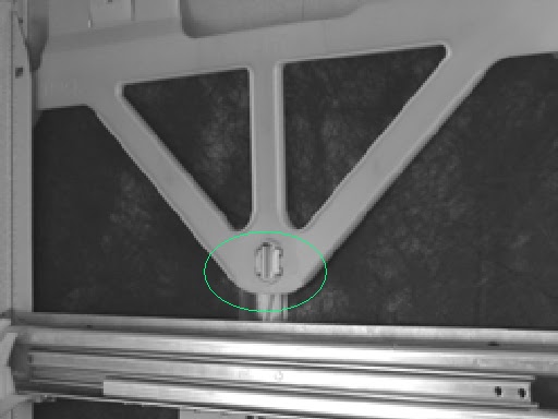
- Locate draw pin on either side of the tub.
- Using a sharp pair of long nose pliers or slip jaw pliers grasp the center dividing web of the pin and pull away from the tub to remove the pin. Support the drawer front with your hand while doing this. Note: The pin web is vertical.
- With both pins removed the bottom of the drawer front can now be eased out slightly.
- Now carefully pull the drawer front down to allow it to come free from the handle and top locating slots.
- Carefully remove the earth wire from the tab on the drawer front. (if it is an integrated model you will also need to unplug the integrated badge from the isolating module)
- Refit in reverse manner ensuring the drawer slides are right forward and the pin secures through the hook on the front end of the slide.
- Note: When reinserting the pins make sure the dividing web is vertical.


TUB REMOVAL
- Open the drawer fully.
- Depress the right-hand tub clip and push it back about 30mm (1 inch). Repeat for the left-hand side.
- The tub may now be lifted up off the drawer runners.
- Slide both runners back into the product.
- Refit in reverse manner.


DRAWER AND LCD DISPLAY REMOVAL
- Remove the drawer front as per instructions given above.
- The handle fits onto a lip at the top of the tub and then slides from left to right to lock into place. Push the right-hand end of the handle to the left until it feels free then remove it out towards you.
- Disconnect the six wire harness from the electronic controller to the LCD interface.
- The handle may now be lifted clear. The LCD display is held in place by a spring tab on one end and a clip in the center. Use a small blade screwdriver to carefully release the tab and center clip as shown. The LCD assembly can now be removed.
- The wiring harness can now be unplugged from the LCD.
- Refit in reverse manner.


DRYING FAN REMOVAL
- Remove the drawer front as per instructions.
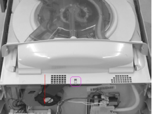
- With a small bladed screwdriver carefully release the small plastic clips holding the rinse aid indication LED in place and remove the LED.
- Slide forward the drying fan duct and remove.
- Disconnect the four wire harness from the electronic controller
- Release the three securing tabs that hold the drying fan in place while applying forward pressure on the drying fan.
- The drying fan will now come free.
- Refit in reverse manner.

DETERGENT DISPENSER
- Disconnect the two wiring loom connections off the dispenser coils. Note: Push back locking tabs to allow connectors to release.
- With a small bladed screwdriver carefully release the small plastic clips holding the rinse aid indication LED in place and remove the LED.
- Unclip the fill hose on the dispenser
- While holding the dispenser unscrew the six T10 Torx drive screws securing the brackets around the dispenser.
- The dispenser can now be removed from inside the tub.
- To open up the dispenser door fully, first open the door using the release catch then squeeze the top sides of the door. This will release the door to the fully open position. This can be done with the dispenser in place.
FISHER AND PAYKEL DISH DRYER DD603 DD6031 DS603 DISASSEMBLE PROCEDURE

ELECTRONIC CONTROLLER
- Disconnect all the wiring connectors on the controller apart from the LCD/Badge plug.
- Now release the clip on the right-hand side of the controller just below the light pipes by firmly pushing it in towards the controller.
- The bottom of the controller can now be lifted out to an angle of about 45_ at which point the top of the controller will come free.
- Disconnect the LCD/Badge plug.

FILTER PLATE & ROTOR ASSEMBLY REMOVAL
- Remove the lower racks from the tub.
- Remove the drain filter assembly.
- Rotate the filter plate locknut anti-clockwise to release the filter plate from the rotor assembly.
- Lift the filter plate clear.
- Rotate the rotor locking ring anti clockwise to release it from the motor assembly and lift out.
- The rotor assembly is not serviceable.
WIRING COVER REMOVAL
- With the tub opened release the tub clips and push back the drawer rails as explained.
- Carefully release the four wiring cover clips from the front lower section of the tub taking care not to damage them.
- Release the three clips on the underside of the tub which retain the wiring cover.
- Pull the tub fully open and lift it up at the front (this makes it easier to remove the wiring cover from the rear of the tub).
- The wiring cover may now be carefully moved forward to release it from the rear of the tub.
- To reassemble first ensure that the wiring harnesses, drain hose and fill hose are clipped into their correct position.


TUB DISCONNECTION
- Disconnect the fill hose from the dispenser (water may drip).
- Disconnect the chassis harness plug from the electronic controller.
- Disconnect the element harness plug and earth wire from the element plate.
- Unclip the drain hose cuff from the motor assembly taking care not to misplace the non-return flap valve.
- Unclip the drain hose, fill hose and the wiring loom from the under side of the tub.
- Now remove the tub.


ROTOR SENSOR REMOVAL
- Unplug the wiring connection from the rotor sensor.
- Release the tab locking the rotor sensor in place as shown and lift the rotor sensor out.


FISHER AND PAYKEL DISH DRYER DD603 _ DD6031 _ DS603 _ DISASSEMBLE PROCEDURE
LOCKING RING, ELEMENT PLATE & MOTOR ASSEMBLY REMOVAL
- Remove the wiring cover and disconnect and remove the tub.
- Unplug the motor wiring harness from the electronic controller.
- While lifting the tab on the locking ring as shown, rotate the ring anti-clockwise until it comes free of tub tabs.
- Take care not to damage any motor wiring as the locking ring is turned (refer picture).
- This also releases the motor housing from the locking ring.
- Holding the pump housing on the motor assembly lift the locking ring, heating plate and motor clear of the tub.
- The suction pipe of the drain molding will slide out of the tub drain area.
- You may now lift the locking ring clear of the motor assembly. This will allow the heater plate and motor assembly to come apart
- Be careful of the two large ‘O’ rings which seal between the motor assembly and heater plate and the heater plate and tub, these and the tub sealing area must be clean and put in the correct place before reassembly takes place.
- Check both the drain cuff ‘O’ ring and suction pipe ‘O’ ring for deformation and damage. Lubricate and if necessary replace ‘O’ rings before reassembly.
- Reassemble in reverse manner ensuring all locking ring tabs are engaged.


LID REMOVAL
- On the right-hand side of the lid release the two tabs that clip the lid to the yoke. Repeat for the left-hand side.
- The lid is now free to slide out of the chassis.
- Refit in the reverse manner taking care that the lid is fitted the correct way around. The front is indicated on the top of the lid.


YOKE REMOVAL
- Release the lid actuator connecting arm from the bottom of the yoke by squeezing the two tabs towards each other.
- Slide the front of the yoke downwards at an angle until it moves out of the track in the rear of the trim, and is clear of the chassis flange.
- Refit in the reverse manner taking care that the yoke is the correct way around.

LID ACTUATOR REMOVAL
- For top tub lid actuators the bottom tub must also be removed to gain access to the lid actuator wiring harness.
- Release the lid actuator connecting arm from the bottom of the yoke by squeezing the two tabs towards each other.
- Remove the cover from the chassis module as explained in
- Disconnect the appropriate lid actuator wiring harness from the chassis circuit board and unclip the wiring harness back to the lid actuator.
- For a right-hand lid actuator carefully release the clip at the back of the lid actuator and slide the lid actuator towards the rear of the chassis to release it from the slide rail.
- For a left-hand lid actuator the clip is at the front of the lid actuator and once released the lid actuator will slide towards the front of the chassis to release it from the slide rail.
- The lid actuator can now be removed.
- When reconnecting a lid actuator to a yoke it is recommended to have the lid and yoke assembly pushed hard up against the upper stops. To line up correctly, the lid actuator connecting arm screw may need to be wound up or down manually prior to clipping to the yoke. Care needs to be taken when working on a lower tub that the lid and yoke assembly don’t accidentally get fitted above the upper stops. Note; it is important that all the clips on the lid actuator case are done up and that none are broken.


SIDE RAIL REPLACEMENT
- Remove the lid actuator from the slide rail as per instructions.
- Bottom slide rails only. The lower plastic chassis trim must be removed to gain access to the screws securing the front of the slide rail. Remove the two hex drive screws securing the slide runner at the front.
- Tap the slide rails from underneath at the front. This will knock the slide rail up and free from its location in the chassis.
- The slide runner may now be pulled forward to release it from its location in the rear of the chassis.


FISHER & PAYKEL DISHDRYER DD603 _ DD6031 _ DS603 _ DISASSEMBLE PROCEDURE
CHASSIS CIRCUIT BOARD _ FLOOD SENSOR REMOVAL
- Release clip on chassis module cover and slide cover to the right to remove.
- Disconnect all wiring to the chassis circuit board taking care not to damage the small lid actuator motor plugs.
- Remove center earth screw from chassis circuit board.
- Release the clip holding the left-hand end of the circuit board down.
- Carefully lift the left-hand end of the circuit board up and then to the left taking care not to damage the flood sensor


WATER VALVE REMOVAL
- Remove the chassis module cover.
- Disconnect the wiring connections to both solenoid coils. Release the locking tabs for the connectors with a blade screwdriver while doing this.
- Disconnect the inlet hose connection.
- You can now slide the water valve up out of its mounting bracket.
- Disconnect the two fill hoses off the valve noting which hose goes to the top and tub and which goes to the bottom tub.


FILL HOSE - DRAIN HOSE - WIRING HARNESS REPLACEMENT
- From the tub end disconnect the component you need to replace (fill hose, drain hose, wiring harness).
- Remove the relevant component from each of the three link clips and the chassis clips holding it.
- Do this one at a time marking its position at each clip in the link and closing each clip after the component is removed to keep the other two components clipped in the correct position.
- The component can now be disconnected from the chassis end and removed.


- Mark the position of the link support clips on the fill hose, drain hose and harness.
- Undo the clips and remove the link support.
- Fit the new link support.
- Check the clips are in the same position as the original. The wire ties on the wiring harness need to be located inside the clips
- If they are not, it could prevent the tub from closing fully, which may cause the product to “Pause” part way through the cycle, or the link support may interfere with and reset the latch while the Drawer is closing.

TOE KICK REMOVAL
- Partly open bottom drawer.
- Loosen the right and left hand toe kick screws.
- Slide the toe kick towards the front of the tub until it comes of the mounting rails.

LOWER CUB COWLING
- Release the center clip as shown and slide the cowling forward.
FOOT TRIM REPLACEMENT
- First remove both the left and right hand yokes as per instructions. This is to prevent damaging the locating tab at the front of each yoke which fits into the trim.
- The trim has to be removed by breaking the retaining clips.
- This can be done by slipping a blade screwdriver between the trim and the chassis and twisting the blade to snap the clips. Protect the cabinet from chipping and remove the broken clips so they don’t fall in to the tub and damage the rotor.
- Check that a light prism is fitted in to the trim.
- Remove the drawer front and handle as per instructions so the replacement trim can be fitted over the tub.
- Line up the clips on the replacement trim with the holes in the chassis and push home.

WATER SOFTENER
- Disconnect the Wiring Loom connections to the Water Softener Diverter valve, Brine pump and Salt Level Detector and remove the Dispenser Wiring Loom connection to the Electronic Controller.
- Use a flat bedded screwdriver to open the Salt Level Indicator LED cover and remove the LED from the Water Softener.
- Unclip the Fill Hose and the Dispenser Hose form the Water Softener.
- Remove the 4 T10 torx drive screws securing the Water Softener to the Tub
- The Water Softener can now be removed from the Product
- To refit, place the Overflow O’ring on the Water Softener and lubricate the Tub overflow with a water soluble lubricant e.g Glycerol or similar.
- Place the Salt Tank O’ring in the tub. Lubricate the Salt Tank flange on the Water Softener.
- Pass the Dispenser Wiring Loom through the Water Softener and plug it into the Electronic Controller.
- Place the Water Softener in the Tub and apply enough pressure to seat the O’rings. The Overflow should sit almost flush with the inside of the Tub. The Salt Tank should be recessed by approx. 1mm from the inside of the Tub.