REPAIRING AND NOT THROWING AWAY

Richtige Fernseher haben Röhren!

Richtige Fernseher haben Röhren!

In Brief: On this site you will find pictures and technical information about Service Modes, Circuit Diagrams, Firmware Update procedure, Disassemble procedure, Universal remote control set-up codes, Troubleshooting and more....

If you go into the profession, you will obtain or have access to a variety of tech tips databases HERE IT IS Master Electronics Repair !.

These are an excellent investment where the saying: 'time-is-money' rules. However, to learn, you need to develop a general troubleshooting approach - a logical, methodical, method of narrowing down the problem. A tech tip database might suggest: 'Replace C536' for a particular symptom. This is good advice for a specific problem on one model. However, what you really want to understand is why C536 was the cause and how to pinpoint the culprit in general even if you don't have a service manual or schematic and your tech tip database doesn't have an entry for your sick TV or VCR.

While schematics are nice, you won't always have them or be able to justify the purchase for a one-of repair. Therefore, in many cases, some reverse engineering will be necessary. The time will be well spent since even if you don't see another instance of the same model in your entire lifetime, you will have learned something in the process that can be applied to other equipment problems.
As always, when you get stuck, checking out a tech-tips database may quickly identify your problem and solution.In that case, you can greatly simplify your troubleshooting or at least confirm a diagnosis before ordering parts.

Happy repairing!
Today, the West is headed for the abyss. For the ultimate fate of our disposable society is for that society itself to be disposed of. And this will happen sooner, rather than later.

How to use the site:

- If you landed here via any Search Engine, you will get what you searched for and you can search more using the search this blog feature provided by Google. You can visit more posts scrolling the left blog archive of all posts of the month/year,
or you can click on the main photo-page to start from the main page. Doing so it starts from the most recent post to the older post simple clicking on the Older Post button on the bottom of each page after reading , post after post.

You can even visit all posts, time to time, when reaching the bottom end of each page and click on the Older Post button.

- If you arrived here at the main page via bookmark you can visit all the site scrolling the left blog archive of all posts of the month/year pointing were you want , or more simple You can even visit all blog posts, from newer to older, clicking at the end of each bottom page on the Older Post button.
So you can see all the blog/site content surfing all pages in it.

- The search this blog feature provided by Google is a real search engine. If you're pointing particular things it will search IT for you; or you can place a brand name in the search query at your choice and visit all results page by page. It's useful since the content of the site is very large.

Note that if you don't find what you searched for, try it after a period of time; the site is a never ending job !

..............The bitterness of poor quality is remembered long after the sweetness of todays funny gadgets low price has faded from memory........ . . . . . .....
Don't forget the past, the end of the world is upon us! Pretty soon it will all turn to dust!

©2010, 2011, 2012, 2013, 2014 Frank Sharp - You do not have permission to copy photos and words from this blog, and any content may be never used it for auctions or commercial purposes, however feel free to post anything you see here with a courtesy link back, btw a link to the original post here , is mandatory.
All posts are presented here for informative, historical and educative purposes as applicable within fair use. NOTHING HERE IS FOR SALE !

Showing posts with label MICROWAVE-OVEN. Show all posts

Wednesday, 10 April 2019

HOW TO TEST A MICROWAVE OVEN MAGNETRON

How to test a Microwave oven Magnetron

Magnetron Test for Opens, shorts or Insufficient Power
Unplug the unit
Discharge all the H.V Capacitors.
Disconnect all the leads (connectors) from the magnetron terminals.
Step 1
Using an Ohm meter on its lowest resistance scale, measure the
resistance from one magnetron terminal to the other in either direction as shown on the illustration.
Meter should read less than 1Ω indicating that the filament is good. If Filament checks good, proceed to Step 2
Step 2
Using an Ohm meter on its highest resistance scale, measure the resistance from one of the magnetron terminals to the metal casing of the magnetron as shown on the illustration on the left.
Meter should read infinity (open circuit) regardless of meter polarity.
If the meter indicates a short (Less than 1 Ω), the magnetron is defective.
The following temperature test will indicate if a magnetron is weak. Make sure unit is plugged in.
1. Fill a beaker or cup with EXACTLY 8 oz (1 Cup) tap water.
2. Record the temperature of the water (Should be approx. 70o F)
3. Place it in the center of the microwave and heat it for the time specified*.
4. Water should be boiling. Record the temperature again.
5. Temperature should rise approximately 142o F (Go to Step 6 only if temperature rise is considerably lower than 142o F otherwise all magnetrons are functioning properly)
6. To test for the weak magnetron, connect one magnetron at a time and repeat Steps 1-4.
a. For ovens that contain 2 magnetrons (NE1257R, NE1258R, NE1757R, NE2157R), the temperature rise should be approximately 70o F per magnetron.
b.For ovens that contain 4 magnetrons (NE2180, NE3280), the temperature rise should be approximately 35o F per magnetron.
Field Expedient Power Determination Tests:
All times calculated using water starting at 70°F {21°C} brought to 212°F {100°C}.
Times given below should serve as the benchmark.
MODEL AMOUNT OF
WATER: VESSEL: TIME:
NE-1257/8 1 CUP PYREX MEASURE 2:15
NE-1757 1 CUP PYREX MEASURE 1:35
NE-2157 1 CUP PYREX MEASURE 0:54
NE-2180 1 CUP PYREX MEASURE 0:54
NE-3280 1 CUP PYREX MEASURE 0:40

Bose Solo 5 – Disassembling procedure
PCB Cover Removal
Remove the 6 screws indicated in Figure. Lift off the PCB Cover
Main PCB Removal
Disconnect the bluetooth antenna connector as indicated from the main PCB.
Note: Use care when removing the antenna connector as it is fragile.
Using a spudger, lift up the PCB and then pull it forward so the rear connectors clear the enclosure openings.
If needed, push the USB port gently with the spudger to help remove the main PCB.
Once the PCB is out from the enclosure, you will notice the transducer harness is at tached to the PCB.
Detach the transducer cable from the main PCB.
Note: Use a spudger or screw driver to re lease the locking tab from the transducer cable.
Metal Grille Removal
On the bottom of the unit, remove the two screws securing the grille as indicated in  Figure.
Then using a spudger, push the grille at the edge to move the metal grille forward from enclosure. Repeat this process for both side of the grille. This will create some space for your fingers later.
Turn the unit over. Grasp the grille by the sides and pull forward to release the grille edge from the enclosure.
Figures showing the locations for the grille guides from left, center and right. Work the grille out of the enclosure using care not to bend the grille.
Note: When installing the metal grille, make sure the grille is inserted in the grille guides as indicated in figures. Ensure this is done properly to ensure proper grille alignment.
Transducer removal
Then on the front of the unit, remove the eight screws securing the 2 transducers as indicated in Figure.
As figure shows the transducer harness goes through the enclosure. To remove the driver, detach the driver from the harness. On the driver, peel off the foam attached to the cable harness to reveal the connector.
Remove the wires from the drivers.
Note: If you confirmed the transducer is defective. You may skip this steps by cutting the cables from the transducer.
During the transducer assembly, ensure that the foam wires side are facing the square opening to the enclosure.
Note: This step ensure enough space for the harness to move into the enclosure without damaging it.

Wednesday, 3 April 2019

AKIRA MICROWAVE OVEN - MW700M17L - TROUBLESHOOTING - SCHEMATIC

AKIRA MICROWAVE OVEN - MW700M17L - TROUBLESHOOTING - SCHEMATIC


WIRING
TROUBLESHOOTING
THERMAL PROTECTOR REMOVAL
1.  Unplug the power cord, remove the outer cabinet and discharge the capacitor.
2.  Disconnect the connectors from the thermal protector terminals.
3.  Remove the thermal protector mounting screw.
4.  Remove the thermal protector.
5.  Reverse procedure to replace.
MAGNETRON ASSEMBLY REMOVAL
1.  Unplug the power cord, remove the cabinet and discharge the capacitor.
2.  Remove the front and rear air guides and thermal protector from the magnetron.
3.  Remove the four-magnetron mounting screws from the side of oven cavity.
4.  Disconnect wire leads from magnetron and replace on new magnetron, wire for wire.
5.  Reverse the above procedure to reinstall new magnetron and reassemble.
NOTE: DO NOT LOSE SCREWS, THEY ARE M4 METRIC.
IMPORTANT: DO NOT OPERATE THE OVEN WITH THE MAGNETRON DISASSEMBLED FROM THE WAVE-GUIDE
Thermal Protector

Saturday, 30 March 2019

GOLDSTAR MV1615W MICROWAVE-OVEN - SCHEMATIC

GOLDSTAR MV1615W MICROWAVE-OVEN - SCHEMATIC

Circuit diagram for Goldstar MV 1615W - Microwave Oven
SPECIFICATIONS
Rated Power Consumption .................................... 1,500W maximum (Microwave oven+Cook top lamp+Ventilation fan)
Microwave Output .................................................. 1,000W (IEC 60705)
Adjustable 100W through 1000W, 10 steps
Frequency .............................................................. 2,450 MHz ± 50 MHz
Power Supply......................................................... 120 VAC, 60 Hz
Rated Current ........................................................ 13 Amp. (Microwave oven+Cook top lamps+Ventilation fan)
Magnetron Cooling................................................. Forced Air Cooling
Rectification ........................................................... Rectification Voltage Double Half-Wave
Door Sealing ......................................................... Choke System
Safety Devices ...................................................... Oven Cavity Thermostat:
Open at 90°C±5°C
Fuse(20A)
Primary Interlock Switch
Secondary Interlock Switch
Interlock Monitor
Magnetron ............................................................. 2M214-39F
High Voltage Capacitor ......................................... Capacitor: 1.0µF, 2.1 KV AC
High Voltage ......................................................... Diode Diode; 350mA, 9.0 KV
Cook top Lamp ...................................................... 125 V, 30 W
Cavity Lamp .......................................................... 125 V, 30 W
Timer ..................................................................... Digital, up to 99 mim. 99 sec. (in each cooking stage)
Tray ....................................................................... Tempered Safety Glass
Overall Dimensions ............................................... 29 15 /16” (W)x16 7 /16” (D)x15 3 /8” (H)
Oven Cavity Size .................................................. 19 7 /8”(W)x14 3 /16”(D)x8 15 /16”(H)
Effective Capacity of Oven Cavity ......................... 1.5 Cu.ft.
Accessories ........................................................... Owner’s Manual & Cooking Guide, Installation Manual, Exhaust Adapter, Exhaust Damper, Mounting Kit and Two Filters, Rotating Ring Assembly.
PRECAUTIONS
SINCE NEARLY 2,100 VOLTS EXISTS IN SOME CIRCUITS OF THIS UNIT REPAIRS SHOULD BE CARRIED OUT WITH GREAT CARE.
The filament leads of magnetron carry High Voltage with respect to ground. Extreme caution must be exercised. Never plug the unit into a power source to determine which component is defective in high voltage section.
> Before the power is applied; (a) Make sure the primary interlock switch, the secondary interlock switch and the interlock monitor switch operate properly by opening and closing the door several by opening and closing the door several times.  (b) Make sure the perforated screen and the dielectric choke of the door are correctly and firmly mounted.
> After power is applied; (a) Make sure the interlock switch mechanism is operating properly by opening and closing the door.  (b) Check microwave energy leakage must
be below the limit of 5 mW/cm2  (All service adjustments should be made for minimum microwave energy leakage readings).
> Do not operate the unit until it is completely repaired, if any of the following conditions exist.  The unit must not be operated.  (a) The door does not close firmly.  (b) The hinge is broken.  (c) The door seal is damaged.  (d) The door is bent or warped, or there is any other visible damage on the unit that may cause microwave energy leakage. [NOTE: Always keep the seal clean.]  (e) Make sure that there are no defective parts in the interlock mechanism.  (f) Make sure that there are no detective parts in the microwave generating and transmission assembly (especially wave-guide).
> The following items should be checked after the unit is repaired.
(a) The interlock monitor switch is connected correctly and firmly.
(b) The magnetron gasket is properly positioned and mounted.
(c) The waveguide and the oven cavity are intact.(no microwave energy leakage)
(d) The door can be properly closed and the safety switches work properly.
(e) The unit must stop when the door is opened or the time is up.
The unit must not be operated with any of the above components removed or by-passed.
SCHEMATIC and PWB
OVERALL CIRCUIT DIAGRAM
CLICK ON THE PICTURES TO MAGNIFY

GOLDSTAR MV1614W - MICROWAVE OVEN HOW TO REMOVE POWER AND CONTROL CIRCUIT BOARD -

HOW TO REMOVE POWER and CONTROL Circuit board - GOLDSTAR MV1614W - MICROWAVE OVEN

Removing the Power and Control Circuit Board - Out case - Door Interlock Switch - Magnatron
HOW TO REMOVE THE POWER CONTROL
* Remove a screw securing the control panel assembly to the oven cavity.
* Remove the control panel with pushing it upward.
* Remove the connector (CN1) and wire leads (Relay6) from the circuit board.
* Remove 2 screws securing the circuit board.
* Remove the FPC connector from the terminal socket following “HOW TO REMOVE THE FPC CONNECTOR”.
* Remove the circuit board from the control bracket carefully.
HOW TO REMOVE THE FPC CONNECTOR
> Hold the edges of the plastic fastener with thumb and forefinger.
>> Lift up the lever of the plastic fastener from the terminal socket by lightly pressing the lever end with forefinger.
>>> Remove the FPC. connector from the terminal socket.
HOW TO INSERT THE FPC CONNECTOR
# Insert the F.P.C. connector into the terminal socket securely with the fingers.
# Hold the plastic fastener with thumb and forefinger of the other hand, and push it slowly into the terminal socket.
NOTE: When reconnecting the F.P.C connector make sure that the holes on the F.P.C. connector are properly engaged with the hooks on the plastic fastener
# Lock the level of the plastic fastener into the hook of the terminal socket securely by releasing the fingers.
HOW TO REMOVE THE OUT-CASE
* Remove the vent grille by removing two screws securing it to the out case.
* Remove two screws securing it to the front bracket.
* Remove two screws securing it to the air duct.
* Remove the mounting plate by turning the two screws securing it to the out case.
* Remove the base plate by removing six screws securing it to the out case. Remove the Mount, All from the out case by removing two screws securing it to the out case and one screw securing it to the ventilation motor ASS'Y and cavity.
* Remove the power cord cover from out case by removing a screw.
* Remove the power cord to the inner of the out case with turning power cord and remove the out case with pushing it back.
REMOVING THE DOOR INTER-LOCK SWITCH
1. Disconnect the wire leads from the interlock switches.
2. Remove two screws securing the Latch Board.
3. Make necessary replacements and check microwave energy leakage.
MAGNATRON REMOVAL
A. Remove vertgrille.
B. Remove mount all.
C. Remove out case.
D. Disconnect the wire leads.
E. Remove the 3 screws and Magnetron very carefully.
> When removing the magnetron, make sure that its dome does not hit any adjacent parts, or it may be damaged.
> When replacing the magnetron, be sure to install the magnetron gasket in the correct position and be sure that the gasket is in good condition.
> After replacing the magnetron, check for microwave energy leakage with a survey meter Check microwave energy leakage must be below the limit of 5 mW/cm2
. (All service adjustments should be made for minimum microwave energy leakage readings.)
CLICK ON THE PICTURES TO ZOOM IN

Friday, 29 March 2019

SHARP R-1900J COMMERCIAL MICROWAVE OVEN ERROR CODES

SHARP R-1900J COMMERCIAL MICROWAVE OVEN Error Codes

Error Codes details _ Sharp Microwave oven Model R 1900J
* When a basic performance and the function are ruined > Displaying and heating stop > EE0, EE1, EE2, EE3, EE8
* When the dangers of the state of the high temperature and the ignition, etc. are foreseen > Displaying and heating stop > EE7
* When you mistake the setting of the heating time > Operation stop > EE9
* When neither the power supply nor the environmental condition are proper > Operation stop > EE4, EE5, EE6
* When informing of the exchange time of parts > Display Only > CC1, CC2, CC3, CC4
If the power supply voltage is higher than 240V+10% (264V), EE4 will be displayed.
If the power supply voltage is lower than 230V-12% (202V), EE5 will be displayed.
o”means that the parts should be replaced if EE11, EE21, EE31 or EE81 is indicated on the display when error histories are checked.
Click on the table to Zoom In
1. If the magnetrons are used for more than 4000 hours, EE11, EE21 or EE31 will appear when error histories are checked.
2.  If the on/off counts of the relay (RY2 or RY3) become more than 400000 times, EE81 will appear when error histories are checked.
3. Even if EE11, EE21, EE31 or EE81 appears when error histories are checked, if the oven is not operated for 3 minutes or more, or if the oven is disconnected from the power supply once and then the oven is connected to the power supply, the oven can be operated once more. But after that when the oven is going to be used again, EE1, EE2, EE3 or EE8 will appear and the oven will not operate.

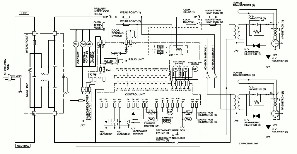
MICROWAVE OVEN CIRCUIT DIAGRAM SHARP MODEL R 1900J

MICROWAVE OVEN CIRCUIT DIAGRAM SHARP Model R 1900J

SHARP S6903 - R1900PJ - R-1900J MICROWAVE OVEN SCHEMATIC
CIRCUIT DIAGRAMS
1. DOOR CLOSED.
2. PLUGGED IN OVEN.
3. NOTHING APPEAR ON DISPLAY
Oven Schematic-OFF condition right after the oven is plugged in.
4. DOOR OPENED.
5. “0” APPEAR ON DISPLAY.
Oven Schematic-OFF condition when the oven door is opened.
6. DOOR CLOSED.
7. “0” APPEAR ON DISPLAY
The relay RY4 will open if the oven is not operated for 3 minutes or more. And the oven condition will go back.
Oven Schematic-OFF condition after the oven door is closed.
1. DOOR CLOSED.
2. MANUAL/ REPEAT PAD TOUCHED.
3. COOKING TIME PROGRAMMED.
4. STRAT PAD TOUCHED.
Oven Schematic-Cooking Condition.
CLICK ON THE SCHEMATICS TO ZOOM IN

HOW TO CHECK THE MAGNATRON OF MICROWAVE OVEN - TESTING PROCEDURE

HOW TO CHECK THE MAGNATRON OF MICROWAVE OVEN - Testing Procedure

Sharp R1900J Microwave oven _ Testing Procedure
MAGNETRON TEST
 
NEVER TOUCH ANY PART IN THE CIRCUIT WITH YOUR HAND OR AN INSULATED TOOL WHILE THE OVEN IS IN OPERATION
 
When the magnetron MG1 and/or MG2 is replacing, the relays (RY3 and RY4) on control unit must be replaced at the same time. Because if the magnetron's life has been over, the relay's life may also be over.
Isolate the magnetron from high voltage circuit by removing all leads connected to filament terminal.
To test for an open circuit filament use an ohmmeter to make a continuity test between the magnetron filament terminals, the meter should show a reading of less than 1 ohm.
To test for short circuit filament to anode condition, connect ohmmeter between one of the filament terminals and the case of the magnetron (ground).
This test should be indicated an infinite resistance. If a low or zero resistance reading is obtained then the magnetron should be replaced.
 
MICROWAVE OUTPUT POWER (1 litre water load)
The following test procedure should be carried out with the microwave oven in a fully assembled condition (outer case fitted). Microwave output power from the magnetron can be measured by IEC test procedure, i.e. it can be measured by using water load how much it can be absorbed by the water load. To measure the microwave output power in the microwave oven, the relation of calorie and watt is used. When P(W) heating works for t (second), approximately P x t/4.187 calorie is generated. On the other hand, if the temperature of the water with V(ml) rises T (°C) during this microwave heating period, the calorie of the water is v x T.
Measuring condition:
1) Container
The water container must be a cylindrical borosilicate glass vessel having a maximum material thickness of 3 mm and an outside diameter of approximately 190 mm.
2) Temperature of the oven and vessel.  The oven and the empty vessel are at ambient temperature prior to the start of the test.
3) Temperature of the water
The initial temperature of the water is (10±1)°C
4) Select the initial and final water temperature so that the maximum difference between the final water temperature and the ambient temperature is 5°C.
5) Select stirring devices and measuring instruments in order to minimize addition or removal of heat.
6) The graduation of the thermometer must be scaled by 0.1°C at minimum and an accurate thermometer.
7) The water load must be (1000±5) g.
8) “t” is measured while the microwave generator is operating at full power. Magnetron filament heat-up time is not included.

NOTE: The operation time of the microwave oven is “t + 3" sec. (3 sec. is magnetron filament heat-up time.)
Measuring method:
1) Measure the initial temperature of the water before the water is added to the vessel.
(Example: The initial temperature T1 = 11°C)
2) Add the 1 litre water to the vessel.
3) Place the load on the centre of the shelf.
4) Operate the microwave oven at HIGH until the temperature of the water rises by a value T of (10±2)K.
5) Stir the water to equalize temperature throughout the vessel.
6) Measure the final water temperature. (Example: The final temperature T2 = 21°C)
7) Calculate the microwave power output P in watts from above formula.
POWER TRANSFORMER TEST
Disconnect the leads to the primary winding of the power transformer. Disconnect the filament and secondary winding connections from the rest of
the HV circuitry. Using an ohmmeter, set on a low range, it is possible to check the continuity of all three winding. The following readings should be
obtained:
a. Primary winding -------------------- approximately 1.3 Ω
b. Secondary winding --------------- approximately 76 Ω
c. Filament winding --------------------------- less than 1 Ω
If the readings obtained are not stated as above, then the power transformer is probably faulty and should be replaced.
 
HIGH VOLTAGE RECTIFIER (1) AND/OR (2) TEST
HIGH VOLTAGE RECTIFIERFTEST
Isolate the high voltage rectifier assembly from the HV circuit. The high voltage rectifier can be tested using an ohmmeter set to its highest range.
Connect the ohmmeter across the terminal B+C of the high voltage rectifier and note the reading obtained. Reverse the meter leads and note this
second reading. The normal resistance is infinite in one direction and more than 100k ohms in the other direction.
 
ASYMMETRIC RECTIFIER TEST
Isolate the high voltage rectifier assembly from the HV circuit. The asymmetric rectifier can be tested using an ohmmeter set to its highest range
across the terminals A+B of the asymmetric rectifier and note the reading obtained. Reverse the meter leads and note this second reading. If an
open circuit is indicated in both directions then the asymmetric rectifier is good. If the asymmetric rectifier is shorted in either direction, then the
asymmetric rectifier is faulty and must be replaced with high voltage rectifier.  When the asymmetric rectifier is defective, check whether magnetron, high voltage rectifier, high voltage wire or filament winding of the power transformer is shorted.
NOTE: Be sure to use an ohm HIGH VOLTAGE CAPACITOR (1) AND/OR (2) TEST
If the capacitor is open, no high voltage will be available to the magnetron. Disconnect input leads and check for short or open between the terminals using an ohmmeter.
Checking with a high ohm scale, if the high voltage capacitor is normal, the meter will indicate continuity for a short time and should indicate an open circuit once the capacitor is charged. If the above is not the case, check the capacitor with an ohmmeter to see if it is shorted between either of the terminals and case. If it is shorted, replace the capacitor.
 
CARRY OUT SECONDARY INTERLOCK SWITCH (1) AND/OR (2) TEST
Isolate the switch and connect the ohmmeter to the common (COM.) and normally open (NO) terminal of the switch. The meter should indicate an open circuit with the door open and a closed circuit with the door closed. If improper operation is indicated, replace the secondary interlock switch.
Isolate the switch (SW1) and connect the ohmmeter to the common (COM.) and normally close (NC) terminal of the switch (SW1). The meter should indicate a close circuit with the door open and an open circuit with the door closed. If improper operation is indicated, replace the switch (SW1).

CARRY OUT 4R CHECKS.T 4PRIMARY INTERLOCK SYSTEM TEST
1. DOOR SENSING SWITCH
2. Isolate the switch and connect the ohmmeter to the common (COM.) and normally open (NO) terminal of the switch. The meter should indicate an open circuit with the door open and a closed circuit with the door closed. If improper operation is indicated, replace the door sensing switch.

3. CARRY OUT 4R CHECKS.
2. PRIMARY INTERLOCK RELAY (RY1)
1. CARRY OUT 3D CHECKS.
2. Disconnect two (2) wire leads from the male tab terminals of the Primary Interlock Relay RY1. Check the state of the relay contacts using a ohmmeter. The relay contacts should be open. If the relay contacts are closed, replace the circuit board entirely or the relay itself.

MONITOR SWITCH (1) AND/OR (2) TEST
Before performing this test, make sure that the secondary interlock switches (1), (2) and the primary interlock relay RY1 are operating properly, according to the above Switch Test Procedure. Disconnect the wire lead from the monitor switches (1), (2) (COM) terminals. Check the monitor switches (1), (2) operation by using the ohmmeter as follows. When the door is open, the meter should indicate a closed circuit. When the monitor switch actuator is pushed by a screw driver through the upper latch hole on the front plate of the oven cavity with the door opened (in this condition the plunger of the monitor switch is pushed in), the meter should indicate an open circuit. If improper operation is indicated, the switch may be defective. After testing the monitor switches reconnect the wire lead to the monitor switch (COM) terminals and check the continuity of the monitor circuit.
 
WEAK POINT TEST.
If the weak point (1) or (2) is blown when the door is opened, check the primary interlock relay RY1, secondary interlock switches (1), (2) and monitor switches (1), (2) according to the “TEST PROCEDURE” for those switches before replacing the blown weak point (1) or (2).

CAUTION: BEFORE REPLACING A BLOWN WEAK POINT (1) OR (2), TEST THE PRIMARY INTERLOCK RELAY RY-1, SECONDARY INTERLOCK SWITCHES (1), (2), DOOR SENSING SWITCH AND MONITOR SWITCHES (1), (2) FOR PROPER OPERATION.
If the weak point is blown, check the magnetron, high voltage capacitor, high voltage rectifier assembly, according to the “TEST PROCEDURE” before replacing the blown weak point. Then replace the weak point.
 
MAGNETRON THERMISTOR TEST
Disconnect the connector of the magnetron thermistor from the harness. Measure the resistance of each thermistor with an ohmmeter. Connect the ohmmeter leads to the connector of each thermistor.
20°C > Approx. 750KOHms.
If the meter does not indicate above resistance, replace the thermistor.
 
POWER UNIT TEST
1. Check the out put voltage of power unit at CN21 as follows.
i) Disconnect the power supply cord, and then remove outer case and rear cover.
ii) Open the door and block it open.
iii) Discharge two high voltage capacitors.
iv) Disconnect the leads to the primary of the power transformer.
v) Ensure that these leads remain isolated from other components and oven chassis by using insulation tape.
vi) Check the voltage between Pin No1 and No2 of CN21.
vii) The output voltage should be approx. 24V.
viii) If not so, the power unit is defective.
2. Check the continuity of the fuse F1 and protector F21 on the power unit as follows.
i) Disconnect the power supply cord, and then remove outer case and rear cover.
ii) Open the door and block it open.
iii) Discharge two high voltage capacitors.
iv) Remove the power unit from the oven, referring to “POWER UNIT REMOVAL”.
v) Check the continuity of the fuse F1 and the protector F21.
vi) If they are open, the power unit is defective.
 
RELAY UNIT TEST
2. Remove the relay unit from the oven, referring to “RELAY UNIT REMOVAL”.
3. Check the continuity of the FUSE1 on the relay unit.
1) If it is open, the relay unit is defective.
4. Check the open and /or short of the transformer primary coil on the relay unit.
1) If it is open and /or short, it is defective.
5. Check the state of the relays contacts RY-1, RY-2 and RY-3 using an ohmmeter.
1) The relay contacts should be open. If not so, the relay unit is defective.
 
MICROWAVE SENSOR TEST
There is no test procedure for the microwave sensor.
When the error history display shows EE18, EE28 or EE38, if the magnetrons, control unit and wiring are normal, the microwave sensor may be defective.
 
CONTROL UNIT TEST
The following symptoms indicate a defective control unit. Before replacing the control unit, perform the Key units test (Procedure O) to determine if control unit is faulty. Connect the power supply cord. And check for followings.
1. In connection with pads.
1) When touching the pads, a certain group of pads do not produce a signal.
2) When touching the pads, no pads produce a signal.
2. In connection with display
1) At a certain digit, all or some segments do not light up.
2) At a certain digit, brightness is low.
3) Only one indicator does not light.
4) The corresponding segments of all digits do not light up; or they continue to light up.
5) Wrong figure appears.
6) A certain group of indicators do not light up.
7) The figure of all digits flicker.
3. Other possible problems caused by defective control unit.
1) Buzzer does not sound or continues to sound.
2) Cooking is not possible.
4. If the protectors F1 and/or F2 on the control unit PWB are open, the control unit is defective. To check, carry out following procedures.
i) Disconnect the power supply cord, and then remove outer case and rear cover.
ii) Open the door and block it open.
iii) Discharge two high voltage capacitors.
iv) Remove the control unit from the control panel.
v) Check the continuity of the KEY UNIT TEST

1. CARRY OUT 3D CHECKS.
2. Check Key unit ribbon connection before replacement.
3. If key unit ribbon connection is normal, carry out the following procedures.
4. Re-install the rear cover and the outer case (cabinet).
5. Reconnect the power supply cord.
6. The following symptoms indicate a defective key unit.
1) When touching the pads, a certain pad produces no signal at all.
2) When touching a number pad, two figures or more are displayed.
3) When touching the pads, sometimes a pad produces no signal.
7. When you cannot judge if the key unit is normal or not by using the item 8 above, carry out following test procedures.

1) Disconnect the power supply cord, and then remove outer case and rear cover.
2) Open the door and block it open.
3) Discharge two high voltage capacitors.
4) Disconnect the leads to the primary of the power transformer.
5) Ensure that these leads remain isolated from other components and oven chassis by using insulation tape.
6) Reconnect the po7) If the display fails to clear when the STOP/CLEAR pad is depressed, first verify the flat ribbon cable is making good contact, verify that the door sensing switch (stop switch) operates properly; that is the contacts are closed when the door is closed and open when the door is open.  If the door sensing switch (stop switch) is good, disconnect the flat ribbon cable that connects the key unit to the control unit and make sure the door sensing switch is closed (either close the door or short the door sensing switch connector). Use the Key unit matrix indicated on the control panel schematic and place a jumper wire between the pins that correspond to the STOP/CLEAR pad making momentary contact. If the control unit responds by clearing with a beep the key unit is faulty and must be replaced. If the control unit does not respond, it is faulty and must be replaced. If a specific pad does not respond, the above method may be used (after clearing the control unit) to determine if the control unit or key pad is at fault.

8) For the door key unit, check the open/short and/or connection of the switch unit and the harness, too.
8. If the Key unit is defective.
1) Disconnect the power supply cord, and then remove outer case and rear cover.
2) Open the door and block it open.
3) Discharge two high voltage capacitors.
4) Replace the Key unit.
5) Reconnect all leads removed from components during testing.
6) Re-install the rear cover and the outer case (cabinet).
7) Reconnect the power supply cord after the rear cover and the outer case are installed.
8) Run the oven and check all functions. Protectors F1 and F2 on the control unit.

HOW TO DISASSEMBLE DAEWOO KOM-9F0CTS MICROWAVE OVEN – WIRING DIAGRAM – CIRCUIT DIAGRAM

HOW TO DISASSEMBLE DAEWOO KOM-9F0CTS Microwave oven – WIRING DIAGRAM – CIRCUIT DIAGRAM

Wiring Diagram_Circuit Diagram_Interlock Mechanism adjustments_Disassembly_DAEWOO KOM-9F0CKS _  KOM-9F0CTS _ Microwave Oven

DIS-ASSEMBLY AND ASSEMBLY
Unlike many other appliances, the microwave oven is high-voltage, high-current equipment.
It is completely safety during normal operation.
However, carelessness in servicing the oven can result in an electric shock or possible danger from a short circuit.
1. Always remove the power plug from the outlet before servicing.
2. Use an insulated screwdriver and wear rubber gloves when servicing the high voltage side.
3. Discharge the high voltage capacitor before touching any oven components or wiring.
Check the grounding.
Do not operate on a 2-wire extension cord.
The microwave oven is designed to be used with grounded.
It is imperative, therefore, to make sure it is grounded properly before beginning repair work.
Warning about the electric charge in the high voltage capacitor.
For about 30 seconds after the operation stopped and electric charge remains in the high voltage capacitor.
When replacing or checking parts, short between oven chassis and the negative high terminal of the high voltage capacitor, by using a properly insulated screwdriver to discharge.
4. When the 20A fuse is blown out due to the operation of the monitor switch; replace primary interlock switch, secondary interlock switch and interlock monitor switch.
5. After repair or replacement of parts, make sure that the screws are properly tightened, and all electrical connections are tightened.
6. Do not operate without cabinet.
 [When servicing the appliance, need a care of touching or replacing high potential parts because of electrical shock or exposing microwave. These parts are as follows - HV Transformer, Magnetron, HV Capacitor, HV Diode.]
To remove cabinet
1) Remove twelve screws on cabinet.
2) Pull the cabinet backward.
To remove control panel assembly
1) Remove three screws which secure the front plate.
2) Remove the control panel assembly from front plate of cavity.
3) Reverse the above for reassembly.
To remove door assembly
1) Open the door assembly and lift the door assembly.
2) Reverse the above for reassembly.
DOOR ASSEMBLY [To remove door parts.]
1) Remove the gasket door from the door assembly.
2) Remove nine screws from the door assembly.
3) Remove the door sub assembly from the door assembly.
4) Remove the stopper hinge *t assembly from the door painting assembly.
5) Remove the spring and the hook.
6) Remove the barrier screen *o from frame door.
7) Remove two screws from frame door.
8) Remove the handle door assembly from frame door.
9) Remove the screw from the handle door assembly.
10) Reverse the above steps for reassemble.
Method to reduce the gap between the door seal and the oven front surface.
To reduce gap located on part ‘A’
• Loosen screws on top of lock and then, close the door with adjusting gap of front surface of oven.
• Tighten screw.
(2) To reduce gap located on part ‘B
• Loosen screws on under of lock and then, close the door with adjusting gap of front surface of oven.
• Tighten screw.
[A small gap may be acceptable if the microwave leakage does not exceed 4mW/cm2.]
To remove high voltage capacitor.
Remove each two screws which secure fore cover exhausts.
2) Remove fourteen screws which secure rear plate assembly.
3) Remove each screw which secures two grounding ring terminal of the H.V. diode and two capacitor holder.
4) Remove two H.V. diode from the capacitor holder.
5) Reverse the above steps for reassembly.
To remove magnetron.
1) Remove each four nuts which secure the magnetrons.
2) Remove the two magnetrons.
3) Reverse the above steps for reassembly.
 [Never install the magnetron without the metallic gasket plate which is packed with each magnetron to prevent microwave leakage. Whenever repair work is carried out on magnetron, check the microwave leakage. It shall not exceed 4mW/cm2 for a fully assembled oven with door normally closed.]
To remove PCB main manual AS, noise-filter.
1) Remove six screws PCB main manual AS.
2) Remove two screws noise-filter.
3) Reverse the above steps for reassembly.
To remove H.V.transformer.
1) Remove each four screws holding the H.V. transformer.
2) Remove the H.V.transformer.
3) Reverse the above steps for reassembly.
To remove lamp.
1) Remove one screw holding the cover ramp.
2) Remove counterclockwise direction lamp from the bracket lamp.
3) Reverse the above steps for reassembly.
To remove motor syncro.
1) Push left side of stopper in centre of cover stirrer and separate it from cavity.
2) Hold side stoppers of ceiling cover with both hands and pull down. Then take off the Ceiling Cover out of the oven cavity
3) Remove three fixture supporter stirrer holding the stirrer *t.
4) Remove stirrer *t from the cavity.
5) Insert a flat-head type screwdriver tray front equivalent approx.
6) Carefully lift up the floor tray by using the screwdriver until the floor shelf is lifted up over the level of oven opening front.
7) Remove tray from the cavity.
8) Remove three fixture supporter stirrer holding the stirrer *u.
9) Remove stirrer *u from the cavity.
10) Remove two screws holding the motor syncro.
11) Remove motor syncro from the cavity.
12) Reverse the above steps for reassembly.
[When replacing the moving antenna, make sure the plastic stirrer spacers are correctly in place.]
INTERLOCK MECHANISM AND ADJUSTMENT
The door lock mechanism is a device which has been specially designed to completely eliminate microwave radiation when the door is opened during operation, and thus to perfectly prevent the danger resulting from the leakage of microwave.
Primary interlock switch and interlock monitor switch
When the door is closed, the hook locks the oven door. If the door is not closed properly, the oven will not operate.
When the door is closed, the hook pushes the lock lever upward. The lock lever presses the button of the primary interlock switch to bring it under NO condition. The lock lever presses the button of the interlock monitor switch to bring it under NO condition.
D.O.M switch
When the door is closed, the hook pushes the lock lever upward. The lock lever presses the button of the primary interlock switch to bring it under NO condition.
ADJUSTMENT 
Interlock monitor switch
When the door is closed, the interlock monitor switch should be changed (NO condition) before other switches are closed.
When the door is opened, the interlock monitor switch should be changed (NC condition) after other switches are opened.
Adjustment steps
a) Loosen two mounting screws.
b) Adjust interlock switch assembly position.
Actuation distance of primary and secondary interlock switch shall be adjusted almost 0mm.
c) Make sure that lock lever moves smoothly after adjustment is completed.
d) Tighten completely two mounting screws.
[Microwave emission test should be performed after adjusting interlock mechanism. If the microwave emission exceeds 4mW/cm2, readjust interlock mechanism.]
COMPONENT TEST PROCEDURE
> High voltage is present at the high voltage terminal of the high voltage transformer during any cooking cycle.
> It is neither necessary nor advisable to attempt measurement of the high voltage.
> Before touching any oven components or wiring, always unplug the oven from its power source and discharge the capacitor.
1. High voltage transformer
(1) Remove connections from the transformer terminals and check continuity.
(2) Normal readings should be as follows :
Secondary winding.......Approx. 100Ω± 10% (110Ω± 10% : KOM-9F0CTS)
Filament winding........................................................................Approx. 0Ω
Primary winding.......................................................................Approx. 15Ω
2. High voltage capacitor
(1) Check continuity of capacitor with meter on the highest OHM scale.
(2) A normal capacitor will show continuity for a short time, and then indicate 10MΩonce the capacitor charged.
(3) A shorted capacitor will show continuous continuity.
(4) An open capacitor will show constant 10MΩ.
(5) Resistance between each terminal and chassis should be infinite.
3. High voltage diode
(1) Isolate the diode from the circuit by disconnecting the leads.
(2) With the ohmmeter set on the highest resistance scale measure the resistance across the diode terminals.
Reverse the meter leads and again observe the resistance reading. Meter with 6V, 9V or higher voltage batteries
should be used to check the front-back resistance of the diode, otherwise an infinite resistance may be read in
both directions. A normal diode’s resistance will be infinite in one direction and several hundred KΩin the other
direction.
4. Magnetron
For complete magnetron diagnosis, refer to "Measurement of the Microwave Power Output." Continuity checks can only indicate and open filament or a shorted magnetron. To diagnose for an open filament or a shorted magnetron,
(1) Isolate magnetron from the circuit by disconnecting the leads.
(2) A continuity check across magnetron filament terminals should indicate 0.1Ωor less.
(3) A continuity check between each filament terminal and magnetron case should read open.
5. Fuse
If the fuse in the primary and monitor switch circuit is blown when the door is opened, check the primary and monitor switch before replacing the blown fuse.
In case the fuse is blown by an improper switch operation, replace the defective switch and fuse at the same time. Replace just the fuse if the switches operate normally.
6. Interlock switches
(1) You can test continuity of safety interlock and monitor switch by using ohmmeter.
(2) The switch operation is checked by zero/unlimited. The meter should indicate zero resistance.
(3) The sequence of check is interlock monitor switch; primary and secondary interlock switches check.
MEASUREMENT OF THE MICROWAVE POWER OUTPUT
Microwave output power can be checked by indirectly measuring the temperature rise of a certain amount of water exposed to the microwave as directed below.
PROCEDURE
1. Microwave power output measurement is made with the microwave oven supplied at rated voltage and operated at its maximum microwave power setting with a load of 1000±5cc of potable water.
2. The water is contained in a cylindrical borosilicate glass vessel having a maximum material thickness of 3mm and an outside diameter of approximately 190mm.
3. The oven and the empty vessel are at ambient temperature prior to the start of the test. The initial temperature of the water is 10±2˚C (50±3.6˚F). If is measured immediately before the water is added to the vessel. After addition of the water to the vessel, the load is immediately placed on the center of the shelf, which is in the lowest normal position.  It is measured immediately before the water is added to the vessel.
After addition of the water to the vessel, the load is immediately placed on the center of the shelf, which is in the lowest normal position.
4. Microwave power is switched on.
5. Heating time should be exactly A seconds.  Heating time is measured while the microwave generator is operating at full power. The filament heat up time for magnetron is not included.
6. The initial and final temperature of water is selected so that the maximum difference between the ambient and final water temperature is 5K.
7. The microwave power output P in watts is calculated from the following formula:
P=4187 X delta T/t
> deltaT: is difference between initial and final temperature.
> t: is the heating time.
The power measured be B  W±10.0 %.
CAUTION
1. Water load should be measured exactly to 1 liter.
2. Input power voltage should be exactly specified voltage
3. Ambient temperature should be 20±2˚C(68±3.6˚F)
MICROWAVE RADIATION TEST
1. Prepare Microwave Energy Survey Meter, 600cc glass beaker, and glass thermometer 100˚C(212˚F).
2. Pour 275cc±15cc of tap water initially at 20±5˚C(68±9˚F) in the 600cc glass beaker with an inside diameter of approx. 85mm(3.5in.).
3. Place it at the center of the tray and set it in a cavity.
4. Close the door and operate the oven.
5. Measure the leakage by using Microwave Energy Survey Meter with dual ranges, set to 2450MHz.
1) Measured radiation leakage must not exceed the value prescribed below. Leakage for a fully assembled oven with door normally closed must be less than 4mW/cm2.
2) When measuring the leakage, always use the 5 cm (2 in.) space cone with probe. Hold the probe perpendicular to the cabinet and door. Place the space cone of the probe on the door, cabinet, door seem, door viewing screen, the exhaust air vents and the suction air vents.
3) Measuring should be in a counter-clockwise direction at a rate of 1 in./sec. If the leakage of the cabinet door seem is unknown, move the probe more slowly.
4) When measuring near a corner of the door, keeps the probe perpendicular to the areas making sure the probe end at the base of the cone does not get closer than 2 in. from any metal. If it does not, erroneous reading may result.
WIRING DIAGRAM
ELECTRONIC CIRCUIT AND COMPONENT LIST
CLICK ON THE PICTURES TO ZOOM IN