REPAIRING AND NOT THROWING AWAY

Richtige Fernseher haben Röhren!

Richtige Fernseher haben Röhren!

In Brief: On this site you will find pictures and technical information about Service Modes, Circuit Diagrams, Firmware Update procedure, Disassemble procedure, Universal remote control set-up codes, Troubleshooting and more....

If you go into the profession, you will obtain or have access to a variety of tech tips databases HERE IT IS Master Electronics Repair !.

These are an excellent investment where the saying: 'time-is-money' rules. However, to learn, you need to develop a general troubleshooting approach - a logical, methodical, method of narrowing down the problem. A tech tip database might suggest: 'Replace C536' for a particular symptom. This is good advice for a specific problem on one model. However, what you really want to understand is why C536 was the cause and how to pinpoint the culprit in general even if you don't have a service manual or schematic and your tech tip database doesn't have an entry for your sick TV or VCR.

While schematics are nice, you won't always have them or be able to justify the purchase for a one-of repair. Therefore, in many cases, some reverse engineering will be necessary. The time will be well spent since even if you don't see another instance of the same model in your entire lifetime, you will have learned something in the process that can be applied to other equipment problems.
As always, when you get stuck, checking out a tech-tips database may quickly identify your problem and solution.In that case, you can greatly simplify your troubleshooting or at least confirm a diagnosis before ordering parts.

Happy repairing!
Today, the West is headed for the abyss. For the ultimate fate of our disposable society is for that society itself to be disposed of. And this will happen sooner, rather than later.

How to use the site:

- If you landed here via any Search Engine, you will get what you searched for and you can search more using the search this blog feature provided by Google. You can visit more posts scrolling the left blog archive of all posts of the month/year,
or you can click on the main photo-page to start from the main page. Doing so it starts from the most recent post to the older post simple clicking on the Older Post button on the bottom of each page after reading , post after post.

You can even visit all posts, time to time, when reaching the bottom end of each page and click on the Older Post button.

- If you arrived here at the main page via bookmark you can visit all the site scrolling the left blog archive of all posts of the month/year pointing were you want , or more simple You can even visit all blog posts, from newer to older, clicking at the end of each bottom page on the Older Post button.
So you can see all the blog/site content surfing all pages in it.

- The search this blog feature provided by Google is a real search engine. If you're pointing particular things it will search IT for you; or you can place a brand name in the search query at your choice and visit all results page by page. It's useful since the content of the site is very large.

Note that if you don't find what you searched for, try it after a period of time; the site is a never ending job !

..............The bitterness of poor quality is remembered long after the sweetness of todays funny gadgets low price has faded from memory........ . . . . . .....
Don't forget the past, the end of the world is upon us! Pretty soon it will all turn to dust!

©2010, 2011, 2012, 2013, 2014 Frank Sharp - You do not have permission to copy photos and words from this blog, and any content may be never used it for auctions or commercial purposes, however feel free to post anything you see here with a courtesy link back, btw a link to the original post here , is mandatory.
All posts are presented here for informative, historical and educative purposes as applicable within fair use. NOTHING HERE IS FOR SALE !

Showing posts with label SHARP. Show all posts

Thursday, 1 October 2020

SHARP LC-46D62U, SHARP LC-52D62U – HOW TO TROUBLESHOOT THE NO-AUDIO PROBLEM

Sharp LC-46D62U, Sharp LC-52D62U – How to troubleshoot the No-Audio problem

No audio [signal inputs] 
No audio HDMI, No audio in all modes 
No audio at digital broadcast signal reception / AT VHF/UHF broadcast
 No audio signal at digital audio output terminal [analog sound OK] 

SHARP XV Z90U, SHARP DT 200 DLP THEATRE PROJECTOR CIRCUIT SCHEMATIC DIAGRAM, HOW TO ENTER THE SERVICE MODE, EXPLODED VIEW – HOW TO DISASSEMBLE, HOW TO RESET THE LAMP

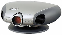
1 - Sharp XV Z90U. Sharp DT 200 DMD Projector – how to disassemble, how to reset the lamp

 The SharpVision XV-Z90U Projector is a SVGA Home Theater Projector. This lamp based projector is capable of displaying 600 Lumens at its brightest setting with a native resolution of 800x600 . The internal DLP technology touts higher contrast, less visible pixels and more portability. The unique projector lens has the ability to be shifted to allow greater flexibility in positioning the projector relative to the screen. This projector was first available for purchase in October 2002 and has been discontinued by SharpVision.


This SHARP projector uses a DMD chip. This very sophisticated chip contains 480,000 pixels. As with any high technology electronic equipment such as large screen TVs, video systems and video cameras, there are certain acceptable tolerances that the equipment must conform to.


This unit has some inactive pixels within acceptable tolerances which may result in inactive dots on the picture screen. This will not affect the picture quality or the life expectancy of the unit.

Service work should be performed only by qualified service technicians who are thoroughly familiar with all safety checks and servicing guidelines.

Be sure to wear sun-glasses when servicing the projector with the lamp turned “on” and the top enclosure removed.


Lamp Replacement

Note:

Since the lamp reaches a very high temperature during units operation replacement of the lamp should be done at least one hour after the power has been turned off. (to allow the lamp to cool off.)

Installing the new lamp, make sure not to touch the lamp (bulb) replace the lamp by holding its reflector.

[Never turn the power on without the lamp to avoid electric-shock or damage of the devices since the stabilizer generates high voltages at its start.]


Connection Pin Assignments
REMOVING OF MAJOR PARTS
Removing the swivel stand and the lamp box.
1-1. Remove lock lever, and remove the swivel stand.
1-2. Loosen 1 scrwew, and remove the lamp door .
1-3. Loosen 3 screws, and take out a lamp box.
Removing the side covers and the top body.
2-1. Push front end of the side cover from bottom, and remove a hook.
2-2. Pull the side cover in the direction of the arrow, and remove it.
2-3. Remove 6 screws and 1connector, and remove a top body.
Removing the main PWB.
3-1. Remove 6 screws.
3-2. Remove each connector on the main PWB.
Removing the power unit.
4-1. Remove each connector on the power PWB.
4-2. Remove 2 screws, and remove the power unit fan.
4-3. Remove 3 screws, and take out the power unit assembly.
4-4. Remove 4 screws, and remove power shield.
Removing the Ballast unit.
5-1. Remove lens shift knob.
5-2. Remove 2 screws, and remove the ballast socket.
5-3. Remove 3 screws, and remove the ballast unit.
5-4. Remove shielding plate, and remove 2 connectors on the ballast PWB.
5-5. Remove 2 screws, and remove ballast PWB.
Removing the optic mechanism unit.
6-1. Remove a connector.
6-2. Remove 6 screws, and remove the optic mechanism Unit
Removing the each other PWBs.
7-1. Remove 1 screw, and remove front R/C receiver PWB unit .
7-2. Remove 1 screw, and remove LED PWB unit.
7-3. Remove 1 screw, and remove a terminal-2 PWB unit.
7-4. Remove 2 screws, and remove an AC socket.
7-5. Remove 1 screw, and remove rear R/C receiver PWB unit.
7-6. Remove 1 screw, and remove DVI-TAN1 PWB unit.
Removing the formatter PWB.  Removing the formatter PWB.
Precautions in replacing the DMD chip

Note: Be careful not to allow dust and fingerprint on the cover glass of DMD chip and prism surface of optical engine.
1. When you fix 4screws of backer plate assembly, press backer plate to formatter PWB and fix by cross multiply step by step.
2. If something shade appears on the projection screen like Fig1, release 2 screws on mirror adjusting plate and move that plate to adjust illumination area of DMD chip.
Precautions in setting up the DMD (Digital Micro mirror Device) unit
Before connecting the formatter PWB to the optical engine, take the following steps. Look at the voltage rank marking that is on the DMD itself. Referring to this marking, set the DIP switches on the formatter PWB. And connect this PWB to the optical engine. Wrong settings will adversely affect the system performance.
Outline of the optical unit
Distinction between long and short focal length lens
• Long focal length lens: focus ring width: about 18 mm > XV-Z90U
• Short focal length lens: focus ring width: about 27 mm > DT-200
Caution when repairing without top cabinet
To repair this set without top cabinet, attach the left side body beforehand. (Since the exhaust heat gets in around the set and the temperature sensor detects it giving the TEMP error and the lamp goes off.)
RESETTING THE TOTAL LAMP TIMER
You need to reset the lamp timer every time you replace the lamp and confirm it is reset on the “Lamp Timer” menu.
• The warning lights on the projector indicate problems inside the projector.
• There are two types of warning lights: a TEMPERATURE WARNING indicator that warns you when the projector is too hot, and a LAMP REPLACEMENT indicator that warns you when to change the lamp.
• If a problem occurs, either the TEMPERATURE WARNING indicator or the LAMP REPLACEMENT indicator will illuminate in red. After turning off the power, follow the procedures given below.
• If the TEMPERATURE WARNING indicator lights up, follow the above possible solutions and then wait until the projector has cooled down completely before turning the power back on. (At least 5 minutes.)
• If the power is turned off and then turned on again, for example during a brief rest, the may be triggered, preventing the power from going on. Should this occur, unplug the power cord from the wall outlet and plug it back in again.


2 - Sharp XV Z90U, Sharp DT 200 DLP theatre projector FULL circuit diagram, how to enter the service mode, exploded view:


 This SHARP projector uses a DMD chip. This very sophisticated chip contains 480,000 pixels. As with any high technology electronic equipment such as large screen TVs, video systems and video cameras, there are certain acceptable tolerances that the equipment must conform to.  This unit has some inactive pixels within acceptable tolerances which may result in inactive dots on the picture screen. This will not affect the picture quality or the life expectancy of the unit.
RESETTING THE TOTAL LAMP TIMER

You need to reset the lamp timer every time you replace the lamp and confirm it is reset on the “Lamp Timer” menu.

How to reset the total lamp timer.

• The warning lights on the projector indicate problems inside the projector.

• There are two types of warning lights: a TEMPERATURE WARNING indicator that warns you when the projector is too hot, and a LAMP REPLACEMENT indicator that warns you when to change the lamp.

• If a problem occurs, either the TEMPERATURE WARNING indicator or the LAMP REPLACEMENT indicator will illuminate in red. After turning off the power, follow the procedures given below.
• If the TEMPERATURE WARNING indicator lights up, follow the above possible solutions and then wait until the projector has cooled down completely before turning the power back on. (At least 5 minutes.)
• If the power is turned off and then turned on again, for example during a brief rest, the may be triggered, preventing the power from going on. Should this occur, unplug the power cord from the wall outlet and plug it back in again.
Entering the adjustment process mode
There are following two methods.
Press the SW2002 on the MAIN PWB.
Press the following keys in this order.
ADJ UP > ADJ UP > ADJ DOWN > ADJ DOWN > ADJ RIGHT > ADJ LEFT > ENTER.

Adjustment mode process menu
Main unit schematic


Formatter schematic


Power unit schematic
Cabinet and mechanical part exploded view
Product type Theatre Projector
Model XV-Z90U/DT-200
Video system PAL/PAL 60/PAL-M/PAL-N/SECAM/NTSC 3.58/NTSC 4.43/DTV 480i/480P/720P/1080i
Display method DLP chip, RGB optical shutter method
DLP panel Panel size: 0.55” (140mm)
Display method: Single Panel Digital Micro mirror Device (DMD™) by Texas Instruments
Drive method: Digital Light Processing (DLP)
No. of dots: 480,000 dots (800 [H] x 600 [V])
Lens 1–1.2 x zoom lens, F1.75–2.04, f=28–33.5 mm (XV-Z90U) F2–2.4, f=16.9–20.2 mm (DT-200)
Projection lamp 150 W SHP lamp
Horizontal resolution 520 TV lines (NTSC 3.58 input)
RGB input signal 15-PIN MINI D-SUB CONNECTOR (INPUT 2):
RGB separate/composite sync/sync on green type analogue input: 0–0.7 Vp-p, positive,75 Ω terminated
HORIZONTAL SYNC. SIGNAL: TTL level (positive/negative) or composite sync (Apple only)
VERTICAL SYNC. SIGNAL: Same as above
Pixel clock 12–110 MHz
Vertical frequency 43–75 Hz
Horizontal frequency 15–70 kHz
Computer control signal 9-pin D-sub connector (RS-232C Port)
Rated voltage AC 100–240 V
Input current 3.6 A
Rated frequency 50/60 Hz
Power consumption 200 W

The SharpVision XV-Z90U Projector is a SVGA Home Theater Projector. This lamp based projector is capable of displaying 600 Lumens at its brightest setting with a native resolution of 800x600 . The internal DLP technology touts higher contrast, less visible pixels and more portability. The unique projector lens has the ability to be shifted to allow greater flexibility in positioning the projector relative to the screen. This projector was first available for purchase in October 2002 and has been discontinued by SharpVision.


Thursday, 20 August 2020

SHARP 14D1 AND 14D2 SERVICE MODE, SERVICE ADJUSTMENTS, HOTEL MODE, ELECTRIC SCHEMATIC DIAGRAM


Sharp 14D1-S/G/W and 14D2-S/G - 18 system color television

Service mode and adjustments

This model's setting are adjusted in two different ways: through the I2C bus control and in the conventional analog manner. The adjustments via the I2C bus control include preset-only items and variable data.  

CAUTION: Make sure TV Set is in "Normal Condition" before switch to Service Mode for adjustment.

Setting the service mode by the microprocessor

Short JA 137 & JA 138 for 1 second and release to switch to the service mode position, and the microprocessor is in input mode. (Adjustment through the I2C bus control). (Use JWS Key to set as well).

Press the CH DOWN / UP key on the remote controller to get ready to select the mode one by one.

Press the CH DOWN / UP key on the remote controller to select the modes reversibly one by one.

Using the VOLUME UP/ DOWN key on the remote controller, the data can be modified.

Short JA 137 & JA 138 for 1 second and release to switch to the normal mode (OFF) position, and the microprocessor is in out of the service mode.

Factory Presetting.

Short JA 137 & JA 138 then turn "ON" the main power and release to switch to the Service Mode position.Initial values are automatically preset, only when a new EEPROM is used (Judge with the first 4 bytes )

The initial data are preset as listed here.

Make sure the data need modify or not (Initial data).

Note: Once the chassis has been assembled together and ready to be POWER ON for the FIRST TIME, make sure to short JA137 & JA138 to switch to the service mode position first and then turn on the main power switch.

If haven't done this initiation, it may possibly generate excessive Beam current.

AFTER SHORT JA 137 & JA 138 ,AND TURN ON THE MAIN POWER SWITCH,READ DATA FROM EEPROM ADDRESS 00H ~ 03H,AND COMPARE TO THE LIST BELOW, IF DIFFERENT, INITIALIZE THE EEPROM.


Direct Key-in for Service Item in Service Mode


INITIAL SETTING

In service mode, After execute select POS 1, store the following tuning data in E2PROM.
Note: All sound system of following channels will be set to B/G or I after pressing INITIAL KEY 2, 3 or 4.


Shipping setting and checking


GA1 Hotel mode application

How to enable or disable the hotel mode.

Press the R/C [function] (1) key until language selection appear, withing five second press the [one/two digit] {2} key and keep pressing it for five second, then you can cee the hotel mode with four digits password.

Key in the four digit password number 1,3,7,9, then the hotel mode will be enabled, and you can switch on/off the hotel mode by using R/C [volume up/ volume Dn {3} key.

It is recommended before set the hotel mode, is better to chose ch1 & set S-Vol level up to 75% full scale.  After set hotel mode, starting channel will be always ch-1 and maximum sound out will be set the half of the full scale.

If you set hotel mode in AV, starting channel will be the last channel which you received before power off [same as normal operation.

Condition

When using the hotel mode, user can cantrol contrast, brightness, sharpness and tint function.

You can’t use:

Preset mode

Fine tuning

Skip mode

System selection

The other function is allowed to be used.

SCHEMATIC DIAGRAM:CRT UNIT and SCHEMATIC DIAGRAM:HEADPHONE UNIT


SCHEMATIC DIAGRAM:MAIN UNIT (14D1-S/G/W)


SCHEMATIC DIAGRAM:MAIN UNIT (14D2-S/G)


PWB


Tuesday, 17 March 2020

REPAIR / SERVICING TV SHARP LC-52XL1RU

Technical description and composition of the TV SHARP LC-52XL1RU, type of panel and applicable modules.
The composition of the modules.
SHARP
Model: LC-52XL1RU
Panel: LK520D3LZ2CY
Inverter (backlight): RUNTKA259WJZZ (6lamp) QKITF0167S1P2 (75-12838Y), n.L. RUNTKA260WJZZ QKITF0167S2P2 (75-14196Y), v.p.
Power Supply (PSU): RDENCA229WJQZ
PWM Power: SPF9001, MC33262D (PFC), STR-W6765 (Standby)
MOSFET Power: 2SK3687
MainBoard: XE191WJTX - KE191 - KE191WE01
IC MainBoard: IXB755WJ, IXB680WJ, IXB946WJ, IXB046WJN1, IXB752WJ, M29DW128
Tuner: QA035WJ
Technical Specifications LC-52XL1RU
SHARP LC-52XL1RU
General recommendations for repairing TV LCD
It is advisable to start diagnosing a malfunction of the SHARP LC-52XL1RU TV, like all others, with an external examination of possible changes, both external and internal elements. Any external damage can sometimes prompt the repairman to take further steps to determine the malfunction of the TV and localize the defect. In some cases, faulty elements can be seen with the naked eye, for example, charred resistors or swollen metal-ceramic capacitors, or electrolytic in rectifier filters. Ring cracks formed in the soldered terminals of transformers or heating elements of the circuit are also frequent sources of many malfunctions with a variety of external manifestations.

In the absence of any signs of operability, when the SHARP LC-52XL1RU does not turn on and does not signal anything with the control lights on the panel, the power module is most likely faulty. When diagnosing and repairing the power supply, first of all, it is necessary to check the fuse and, if it is broken, it is necessary to identify the cause. Often in such cases, an avalanche (thermal) breakdown is detected in the power semiconductor elements of the module — rectifier diodes or power switch J655 pl K3706 pl.
It should be remembered that the N-FET keys used in flyback converters rarely fail for no reason that must be sought by checking other elements of the circuit. Often the breakdown is caused by malfunctions of electrolytic capacitors or semiconductor elements in the primary circuit, or by a break in the resistors in the stabilization circuits. The PWM controller chip can also cause a breakdown of the power switch of the converter.
When using a power factor correction unit (PFC) in the power modules, troubleshooting becomes somewhat more complicated and requires additional experience and knowledge of the device for their operation.
If, when you turn on the TV, the image appears and immediately disappears, or is initially absent when you turn on, but there is sound and other functions work, there is a high probability of a malfunction of the inverter (power converter for the backlight). In such cases, the lamps, the inverter and the common power module are subject to verification, in which the electrolytic capacitors of the rectifier filter feeding the inverter should be checked.

Repair of inverter vl RUNTKA259WJZZ (6l) QKITF0167S1P2 (75-12838Y), nl RUNTKA260WJZZ QKITF0167S2P2 (75-14196Y), vp RUNTKA261WJZZ QKITF0168S3P2 (6Y-0). RUNTKA262WJZZ QKITF0168S4P (74-05477Y) is complicated by the fact that in case of any malfunction or emergency, even if the lamps are unevenly worn, protection is triggered, which turns it off for fire safety purposes. Diagnosis becomes impossible and protection needs to be disabled.

It should be remembered that in such cases there is a risk of failure of the power elements of the inverter and to take special care. After carrying out repairs, the protection circuit must be restored for further safe operation of the TV.
Owners and users of the SHARP LC-52XL1RU TV must remember that self-repair without special knowledge, skills and qualifications can be fraught with negative consequences that can lead to complete non-repairability of the device!

Service Manual with Schematic Diagram 194 pages 2007 on models LC-46XL1E, LC-46XL1RU, LC-52XL1E, LC-52XL1RU.

Service Manual with Schematic Diagram ----- >  Sharp LC-46XL1E, LC-46XL1RU, LC-52XL1E, LC-52XL1RU


 The LC-52XL1RU model uses an RDENCA229WJQZ power supply unit using the PFC (Power Factor Correction) node - an active filter of the highest harmonics of the current consumption. In fact, it is a boost converter based on the MC33262D PWM controller, which eliminates the charge current of the electrolytic capacitor of the rectifier filter directly from the network through open diodes when its charging current is determined by its reactance.
As a result of the operation of the converter, the envelope of the high-frequency pulses of the input current of the converter will repeat the shape and phase of the input voltage. The health of the PFC node can be indirectly judged by the presence of an increased constant voltage (about + 380V) on the capacitor of the rectifier network in operating mode.
Main features of the SHARP LC-52XL1RU device:
Installed matrix (LCD panel) LK520D3LZ2CY.
To power the backlight used inverter RUNTKA259WJZZ.
The necessary supply voltages for all nodes of the SHARP LC-52XL1RU television are generated by the RDENCA229WJQZ power supply module or its analogs using microcircuits SPF9001, MC33262D (PFC), STR-W6765 (Standby) and power switches of the 2SK3687 type.
MainBoard - the main board (motherboard) is an XE191WJTX module, using the IXB755WJ, IXB680WJ, IXB946WJ, IXB046WJN1, IXB752WJ, M29DW128 microcircuits, and others.
The QA035WJ tuner provides TV reception and channel tuning.

 LCD TV SHARP LC-52XL1RU with LCD LK520D3LZ2CY, diagonal size 52 "(132 cm) in 16: 9 format. The brightness of the screen is 450 cd / m² by CCFL (EEFL) fluorescent lamps. Contrast as the ratio of maximum brightness to minimum, not less than 2000: 1. Dynamic contrast ratio of 10000: 1 is achieved by controlling the backlight, depending on the brightness of the plot.
The design and technical capabilities of the TV include watching programs and movies in high quality HD at a resolution of 1920x1080 pixels in a graphical decomposition according to the standard 1080p (Full HD). The input high-frequency or video signal can be processed in analogue systems PAL, SECAM, NTSC. Graphic processing and digital signal generation occurs in standards 480i, 480p, 576i, 576p, 720p, 1080i, 1080p.
Sound power 30 W (2x15 W) provide two speakers. It uses a NICAM stereo signal processing system and Sound Surround.
The external interface (communication with other devices) is supported by standard input and output connectors: antenna input (RF), AV, audio x3, S-Video, SCART x2, RGB, VGA, HDMI x2, RS-232. An output for connecting headphones is provided. To connect a computer or laptop to this TV model, a VGA (D-Sub 15) connector is used on the TV case, this interface supports resolutions: 640x480, 800x600, 1024x768, 1280x1024, 1360x768.
A digital tuner is capable of receiving television channels in DVB-T standards.
The power consumed by the TV from the network in operating mode is 305 watts.
Overall dimensions: with stand 1273x875x309 mm, without stand 1273x812x126 mm.
TV Weight: with stand: 41.8 kg, without stand: 37.2 kg.
Attention! The LK520D3LZ2CY panel of the SHARP LC-52XL1RU LCD TV is its most expensive component.
Avoid hitting the glass and exerting pressure on the screen to avoid permanent damage to the LCD panel!