REPAIRING AND NOT THROWING AWAY

Richtige Fernseher haben Röhren!

Richtige Fernseher haben Röhren!

In Brief: On this site you will find pictures and technical information about Service Modes, Circuit Diagrams, Firmware Update procedure, Disassemble procedure, Universal remote control set-up codes, Troubleshooting and more....

If you go into the profession, you will obtain or have access to a variety of tech tips databases HERE IT IS Master Electronics Repair !.

These are an excellent investment where the saying: 'time-is-money' rules. However, to learn, you need to develop a general troubleshooting approach - a logical, methodical, method of narrowing down the problem. A tech tip database might suggest: 'Replace C536' for a particular symptom. This is good advice for a specific problem on one model. However, what you really want to understand is why C536 was the cause and how to pinpoint the culprit in general even if you don't have a service manual or schematic and your tech tip database doesn't have an entry for your sick TV or VCR.

While schematics are nice, you won't always have them or be able to justify the purchase for a one-of repair. Therefore, in many cases, some reverse engineering will be necessary. The time will be well spent since even if you don't see another instance of the same model in your entire lifetime, you will have learned something in the process that can be applied to other equipment problems.
As always, when you get stuck, checking out a tech-tips database may quickly identify your problem and solution.In that case, you can greatly simplify your troubleshooting or at least confirm a diagnosis before ordering parts.

Happy repairing!
Today, the West is headed for the abyss. For the ultimate fate of our disposable society is for that society itself to be disposed of. And this will happen sooner, rather than later.

How to use the site:

- If you landed here via any Search Engine, you will get what you searched for and you can search more using the search this blog feature provided by Google. You can visit more posts scrolling the left blog archive of all posts of the month/year,
or you can click on the main photo-page to start from the main page. Doing so it starts from the most recent post to the older post simple clicking on the Older Post button on the bottom of each page after reading , post after post.

You can even visit all posts, time to time, when reaching the bottom end of each page and click on the Older Post button.

- If you arrived here at the main page via bookmark you can visit all the site scrolling the left blog archive of all posts of the month/year pointing were you want , or more simple You can even visit all blog posts, from newer to older, clicking at the end of each bottom page on the Older Post button.
So you can see all the blog/site content surfing all pages in it.

- The search this blog feature provided by Google is a real search engine. If you're pointing particular things it will search IT for you; or you can place a brand name in the search query at your choice and visit all results page by page. It's useful since the content of the site is very large.

Note that if you don't find what you searched for, try it after a period of time; the site is a never ending job !

..............The bitterness of poor quality is remembered long after the sweetness of todays funny gadgets low price has faded from memory........ . . . . . .....
Don't forget the past, the end of the world is upon us! Pretty soon it will all turn to dust!

©2010, 2011, 2012, 2013, 2014 Frank Sharp - You do not have permission to copy photos and words from this blog, and any content may be never used it for auctions or commercial purposes, however feel free to post anything you see here with a courtesy link back, btw a link to the original post here , is mandatory.
All posts are presented here for informative, historical and educative purposes as applicable within fair use. NOTHING HERE IS FOR SALE !

Showing posts with label PRIMA. Show all posts

Tuesday, 19 March 2019

PRIMA PS-42D8 B - PS-42D8 S - PH-42D8 - SOFTWARE UPDATE - OPERATION PRINCIPLE OF PLASMA DISPLAY

PRIMA PS-42D8 B - PS-42D8 S - PH-42D8 - SOFTWARE UPDATE - OPERATION PRINCIPLE OF PLASMA DISPLAY


SOFTWARE UPGRADE
The plasma TV models PS-42D8 B/S and PH-42D8 launched by our company are equipped with RS-232 interface for upgrading that is carried in the steps below:

Select a connection wire of serial port (see the figure below), which is required to have a notch on its both ends, and also the pins 2 and 3 on the two ends are cross connected.
  • Use the serial port connection wire to connect PCwith PDP and set PDP to the off position.
  • Open the folder of the upgrading software and double click the FlashUpgraderNT (on condition of window 2000/XP/NT) or the FlashUpgrader (on condition of window 98)

After running the programs the following interfaces will appear:
Based on the features of computer set up the serial port (COM Port) and select corresponding  serial port (if it’s not possible to burnt-write other serial port can be used instead). Baud-select 115200 and then select Reset Target After Download. Hit flash press button and it’s ready to operate. For the setup of other items please refer to the figure above (already defaulted by the system so it’s normally unnecessary to alter)
  • Switch on PDP and it begins to run the burnt-write program;
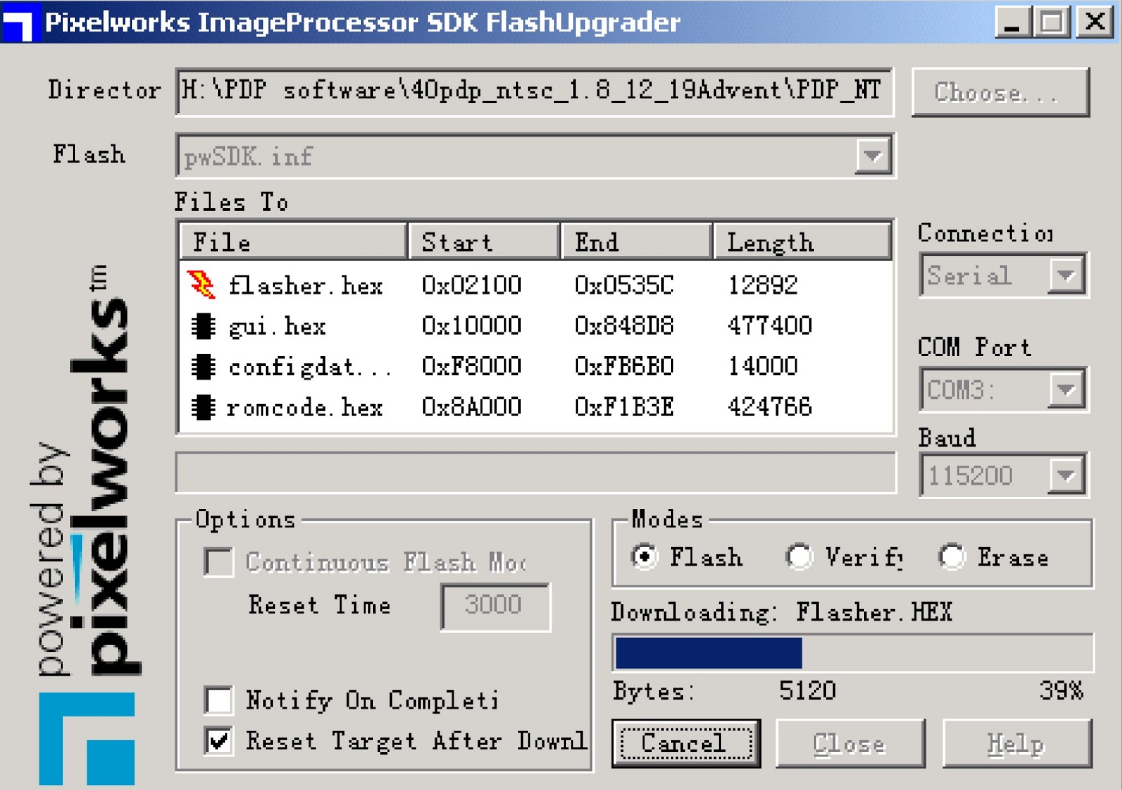
  • Once it’s over with burnt-write, the cancel pushbutton will become flash. Switch off the main power and then to switch on the TV set again.

Note: Do not switch the power or the set off in the course of burnt-writing. Otherwise it may result in the inability of the flash to burnt-write again.
OPERATION PRINCIPLE OF PLASMA DISPLAY
  Plasma plane screen technology represents the state-of-the-art and it’s also the best choice for high quality picture and large purely place screen. Plasma display screen PDP is a display unit employing gas discharge. This screen uses plasma tube as its light emission component. The faceplate (panel)of PDP consists of many image elements (plasma tubes) for example, the series PS ,PH pdp now on the market consists of 852*480 image elements. Each image element in turn consists of three kinds of image sub-elements. Each image element is actually a plasma tube. These tubes are present respectively in red, green and blue colors. Each small chamber that corresponds to each plasma tube is filled with neon and xenon gases. After applying high voltage between the plasma electrodes, the gases in the small chambers of the plasma tubes sealed in the two layers of glass will produce ultraviolet so as to excite the three basic color (red, green and blue) fluorescent powder to emit visible light. Each plasma tube acts as an image element. From the composition of these image elements in different brightness, darkness and colors result the pictures and images of various grays and colors, which is very similar to the light emission of display tube. Plasma technology is obviously different form other display methods and is more advanced in structure and formation. Its working principle is similar to normal daylight lamp. The TV color picture is composed of the light emitted from various independent fluorescent powder image elements and therefore the picture is fresh and gaily colored, bright, clean and clear. Furthermore the most outstanding feature of plasma TV is that it can be made super thin and it’s easy to make TV sets of more than 40” with completely plane big screen but in
thickness less than 100 mm (Our Model PS-42D8 is only 79mm thick and it’s the thinnest in the market at present.)
  Plasma TV model PS-42D8 B/S and PH-42D8 series of XOCECO is designed and developed by XOCECO itself. In terms of the main CMOS chip this series of TV set employs PW181 made by Pixelworks Company.

WORK PROCESS FLOW OF MODEL 'PS' & 'PH' SERIES
  This TV model is based on dual MCU control of which the main MCU is PW181(N501, taking care of the operation of various chips (including image treatment, channel switching, image display etc.), infra red remote control receiving, the standby control, the control of auxiliary CPU, menu display, debugging of picture effects and other major functions. The auxiliary CPU is SDA555X(NM5, which is responsible for sound treatment (including volume adjustment, control of alt and base sound, stereo decode), station searching control, push button, separation of 3D Y/C (valid only for system N) as well as the CCD/V-CHIP decoding for the text for oversea sale TV sets etc. Connection between two MCU is made by means of three pins of X708, i.e., INT (interruption), S1(RXD), S2(TXD).

SOUND VOLUME
  This model employs double integrated tuner (including high frequency and medium amplification circuits). The signal received by antenna is fed to the main tuner, TUNER1, which contains a high frequency distributor, from which RF signal is shunt to supply to TUNER3 for use. Pin 14 of TUNER1 is for the power supply of high frequency distributor (+5v). Tuners are controlled by auxiliary MCU NM5 (SDA and SCL) to select proper channel and carry out correct switching of systems. After high amplification and medium amplification decoding, video signal and audio signal are output. The output signal of TUNER1 is fed into decoder N102 as the display of main picture whereas the output signal of TUNER3 is fed into decoder N302 as the display of the auxiliary picture for dual picture. Audio signal is directly fed into audio frequency processor NM2 MSP3440. At the same time dual way tuners all send their medium frequency signal of the second sound to NM2 for treatment (used for decoding of stereo or automatic sound volume control). NM2 is provided with the switching over device for audio frequency channels. Audio input of VGA/DVI/YprPb of the main board, after the switching-over as selected by N3, is fed together with the audio signal of TV and AV into NM2, where switching over is selected. The selected audio frequency signal is made use of in the following three ways. One way is, after being subjected to the control of volume and alt and base sound, fed separately through left and right sound channels into sound power amplifier TPA3001 for amplification. Then it is fed into the loudspeaker for sound reproduction. Another way is also fed separately through left and right sound channels into earphone power amplifier NM9 TDA7053 for amplification before being output to earphone socket for listening, of which the volume is controlled by PWM signal produced by pin 50 of NM5.The remaining way is output through video board as AV out.
  Sound power amplifier TPA3001 is an amplification of mono-channel high efficiency D type power. Under the condition of no heat dissipation its output power can be as high as 20 w. It has the functions of over current and overheating protection. Automatic protection comes in when the input to the ground is short-circuited. Then output is stopped. After the removal of short circuit, switch the set again and it restores to normal. Therefore if the set becomes soundless due to the short circuit caused in carelessly pulling out or plugging in the audio frequency wire (it is certainly not recommendable to do so), just switch it on again and no big deal.
PICTURE & IMAGE
  Y signal of AV and SVHS shares the same channel. SVHS has priority. Identification of terminal S is determined by electric level SID fed from SVHS socket to NM5. When the electric level of SID is of high value, the system is identified as SVHS. Signals from TV or AV and YCRCB are altogether fed into digital decoder VPC3230 (sent separately in two ways to N102 and N302). Channel switching is carried out. They are decoded into 16bit CCIR601 signal to be fed into the processor of lower level for treatment. VPC3230 mainly functions to switch over channels, separate Y/C of 4 lines, decoding of colors and adjustment of picture effect.
MAIN CHANNEL
  The digital YCRCB signal in the format of CCIR601 after being decoded in N102 is fed into non-interlace processor N204 PW1230 for treatment from alternate-line into non-interlace. VD1_CLK,VD1_HSYNC VD1_VSYNC, VD1_ACTIVE and VD1_FIELD sent from VPC3230 is used as a key signal to identify modes. If certain channels become abnormal the corresponding pictures will also become abnormal. In addition to the function PW1230 has to process the signal from alternate-line into non-interlace, it can also function to enhance the picture and convert the movie modes 3:2/2:2. The adjustment of brightness and contrast of the main channel is performed by this chip whereas the adjustment of chroma and definition is performed by N102. The digital 24 bit RGB signal output from
PW1230 after treatment is fed into V PORT of N501 PW181 for further processing. The signals of VCLK (clock) and VVS(field synchronization) and VHS(line synchronization) and VPEN(enable signal)are the basic reference for the image processing of lower level.
  For TV set of mono N system, this series has an additional 3D Y/C separation function in the main channel, which is performed by ND02 Upd64083 so as to enhance the quality of the image. In this case the signal flow process of the main channel is different. Video signal and AV/SVHS signal sent from TUNER1 first undergo switching in the switch circuit ND01, then are fed into ND 02 for separation of brightness from color and output as signal Y and C. For N102, no matter whether it’s TV or AV/SVHS, finally the signals are all fed in the form of Y/C into the input port of VIN1and CIN. Yet the setup for the software is somewhat different.
  Auxiliary CPU performs the decoding for the text of main channel or CCD/V-CHIP. Video signal is directly fed to pin 12 of NM5 for decoding. The decoded text or CCD/V-CHIP signal is output in the form of R, G, B, FB and fed into N102 for character superposing.
SUB-CHANNEL
  Signal CCIR601 after being decoded in VPC3230 is directly fed into PW181 G PORT where direct processing is carried out by PW181. The non-interlace processor inside PW181 performs the non-interlace conversion in this channel. Relatively speaking, the efficiency of the internal non-interlace processor of PW181 is lower than that of PW1230. Therefore when displaying dual picture the main picture effect is better than that of sub-picture. The adjustment of brightness, contrast, definition and chroma is performed by N302.
  The decoding of CCD/V-CHIP in this channel is specially performed by 21 line decoder N301 Z86229. The decoded information is superposed onto the image in N302 also in the form of R, G, B and FB.
For VGA and YPRPB, after the selection in N1 YPRPB1 and YPRPB2 are fed together with N402 for channel selection. The selected signal is fed into the ADC part of N403 AD9887 for A/D conversion so as to produce 24 bit digital RGB signal to be fed into the G PORT of PW181. The line and field synchronous signal of VGA is directly fed into N403 whereas The line and field synchronous signal of YPRPB is obtained after synchronous separation of Y signal of SOGIN in AD9887 (This signal is input to N403 pin 108).
AD9887 is also provided with DVI input port. The DVI input signal is converted into 48 bit digital RGB signal and sent to G PORT of PW181 for processing. The selection from DVI and VGA/YPRPB is performed by AD9887.Certain organizations for the oversea sales of this TV series have been equipped with the capability to decode HDCP. PORTA4 and PORTA5 of PW181 verify the password (cipher key) through bus line with broadcast equipment. Each TVset has its own independent password, which is stored in EEPROM.
The mode identification of VGA or YPRPB is performed by PW181. The identification process is :
  When selecting channel signal input PW181 presets the synchronous selection of AD9887 so that it can directly output the required synchronous signal for direct feeding to PW181. The synchronous signal format is identified inside PW181. By making cross-reference with the format table pre-stored inside a most similar format is obtained. Then the parameters of this format are called for use in setting up the parameters for modular conversion so that it is optimized. At the same time the conversion coefficient of SCALER is confirmed.
  Finally the video signals of different channels are sent respectively to V PORT and G PORT of main processing chip PW181 for processing. PW181 has such processing capabilities as “picture out of picture”, “picture in picture”, “multiple pictures”. So long as the signals come respectively from V PORT and G PORT, they automatically become “picture out of picture”, “picture in picture”. PW181 has the function of SCALER, which means it can conduct format conversion for the input signals of different format to enable it to meet the requirement of the screen for format and finally output the signal in the form of 24 bit RGB.
  The standard of interface for PDP screen is LVDS (low voltage differential signal). So the digital RGB signal output from PW181 still needs to be converted into LVDS signal by the conversion interface chip of LVDS - N602 DS90C385 (This chip may vary with the manufacturer of the screen). This converted signal is in turn fed to the screen for driving purpose. The output of N602 is four pairs of differential signal and one pair of clock signal. If any pair of signal is abnormal then the image is affected to be abnormal for example, a certain color may become abnormal. The PWRDOWN signal output from PW181 is used to control the operation of N602, which works under low electric level.
  PW181 is also the main CPU. Its program is stored in the externally connected flash N601. The software upgrading of RS-232 is actually the upgrading of the stored memory in N601 by PW181. The interface of menu is also produced by PW181. PW181 can automatically produce self-check signal for troubleshooting.
The above is a short account of the signal flow process of the TV series. Please note HS (Horizontal Synchronous), VS (Vertical Synchronous) and CLK (Clock), PEN (Enable) between individual stages are invariably the basic reference for the mode identification of lower level chip. Make sure that they are in normal working condition.
  PW181 controls the standby of the complete TV set. The POWER-ON signal output from PORTB3 of PW181 is used to control the operation of the power supply board. When it is POWER_ON, the TV set is switched on with low electric level and is in standby with high electric level. When it’s in standby the remaining power supply is only 5VSTBY.
  The voltage VS required by the operation of screen is also controlled by VS_ON output from logic board. It is in operation when the electric level is high. Only when the logic board receives correct signal (clock, synchronous, enable etc.) can VS_ON be correctly output. The operation of PDP screen has very high demand for the time sequence of power supply. If the time sequence is wrong it might make the screen unable to work normally.

PRIMA PS-42D8 B - PS-42D8 S - PH-42D8 - TROUBLE DIAGNOSIS - DISTRIBUTION OF CIRCUIT BOARDS & PART NUMBERS -

PRIMA PS-42D8 B - PS-42D8 S - PH-42D8 - TROUBLE DIAGNOSIS - DISTRIBUTION OF CIRCUIT BOARDS & PART NUMBERS - Universal Remote Controls Setup Codes


PLASMA SCREEN OF 'PS' & 'PH' [TROUBLE DIAGNOSIS]
The screen is not bright:
  • Check to see if the power supply plug from the power filter board to the power supply board is well inserted into the socket. If not, plug it in.
  • Check if the fuse on the power supply board is blown up. If yes, replace it for a good one.
  • Remove our main board and the video frequency processing board, ground the pin 4 POWER_ON/OFF of socket CN802 of the power supply board, and then push the slide switch SW2001 on the logic board to the internal modes (1, 3 up and 2, 4 down) from external modes (1, 2, 4 up and 3down) Switch the power on and see if the screen is lit. If the screen can give a normal and completely white field signal, then the problem lies in our main board or video frequency processing board, which will be dealt with separately.
  • If the screen is not lit, then first replace the power supply board to see if the problem is solved.
  • If the problem remains after the power supply board is replaced, then the problem lies in the screen. Replace the entire screen.
There appears on the screen a line or several unlit lines.
  • Check if the socket between Y driving board and Y BUFFER is plugged well. If not, plug it well. If yes then replace Y BUFFER (upper, lower) in respect to the upper , lower part of the dark line on the screen. 
There appear on the screen one or several horizontal lines that are much brighter than the remaining horizontal lines at the edge:
  • Check if the socket between Y driving board and Y BUFFER is plugged well. If not, plug it well. If yes then replace Y BUFFER (upper, lower) in respect to the upper , lower part of the dark line on the screen.
There appear on the screen one vertical unlit line or a vertical entirely unlit block.
  • If it’s one vertical unlit line, then COF has problem.
  • If it’s a vertical entirely unlit block, then first check if the connection socket between COF and logic BUFFER has problem. If not, check if the connection socket between the logic BUFFER and the logic board is normal. If yes, replace the logic BUFFER. Finally, if the problem still remains when the replacement is over, then replace the logic board.
There appears on the screen a mono color signal and one or several vertical bright lines of other colors:
  • If it’s a vertical bright line of other colors, then the problem lies with COF or the screen.
  • If it’s an entire vertical block of other colors, then first check to see if the connection socket between COF and logic BUFFER has problem. If no problem, check if the connection sockets between the logic BUFFER and the logic board is normal. If it’s normal, then replace the logic BUFFER. If the problem still remains after the replacement, then replace the logic board. Finally if the problem is still there, then the problem lies with COF.
There appear on the screen abnormal bright spots or blocks that are different from what’s described above:
  • Check if the connection socket between COF and logic BUFFER board has been well plugged.
  • Replace the logic BUFFER board. If it’s not solved then replace logic board. If the problem still remains, then it’s the problem with COF.
CIRCUIT BOARDS LAY OUT
42SD-V3(Type: S42 SD-YB03,Code No: 335-42001-00)
42HD-V3 (Type:S42AX-XB01,Code No:335-42002-00)
SIGNAL PROCESSOR BOARDS
PARTS NAME & NUMBERS
CLICK ON PICTURES TO MAGNIFY
SET-UP CODES
GE:  1019 0165 0116 0167
RCA RCR 311W: 1139
RCA RCR 312W: 10761, 10783, 10815, 10817
RCA RCU 300XP 36:  43
RCA RCR N04GR: 10761, 11785
RCA RCR 4383: 10761, 10783, 10815, 10817
RCA RCR 311BN: 10761, 10783, 10815, 10817
AR&T UVERSE: 1113
URC 4140: 0055 0032 0287
URC 2054: 10761,10817,11785,1193

PRIMA PH50D8 - PLASMA TV - TROUBLESHOOTING FLOW CHART

PRIMA PH50D8 - PLASMA TV - TROUBLESHOOTING FLOW CHART - UNIVERSAL REMOTE CONTROLS SET-UP CODES


TROUBLESHOOTING CHART
No raster, No picture and No sound: 

Note: Power supply for PDP is provided with over current and over voltage protection functions. If there is over current or over voltage, this protection will function and no output.
SOUND OK, BUT NO PICTURE
  • For the originally self-powered software, if the operation of PW181 is abnormal, in SDA555X there may be a state of individually switched-on. In this case very often the phenomenon of the trouble is there is sound but no image.

Setting up for the self check of the screen:
  • For 42”SD screen (S42SD-YD04):Push down 2 and 4 and push up 3 of SW2001on the logic board;
  • For 50”HD screen (S50HW-XD02):Push down 1 and 4 and push up 2, 3, 5, 6 of SW2001on the logic board;

Make sure resume it to the original status when the check is over.
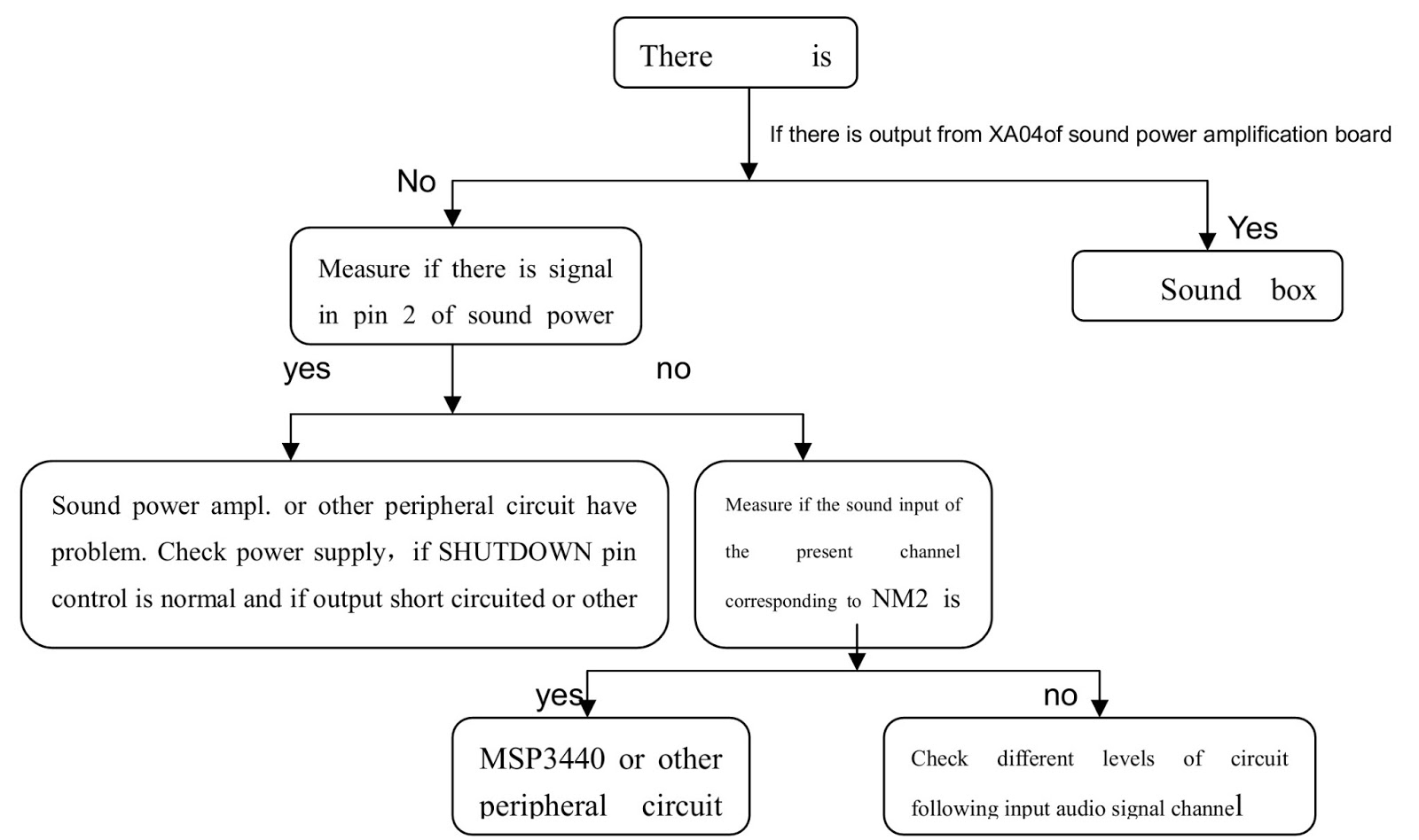
PICTURE OK, BUT NO SOUND
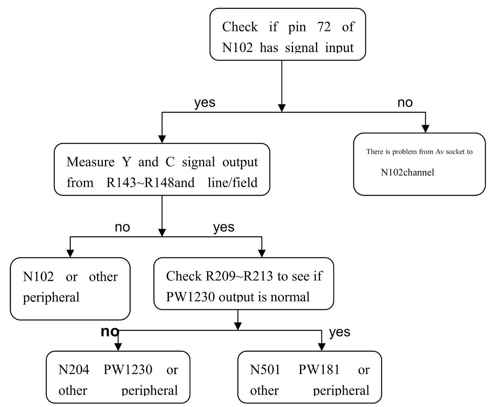
NO PICTURE TO A/V
First, use dual picture function to judge if the main or sub picture has problem.
NO PICTURE IN SUB-CHANNEL
CLICK ON PICTURES TO MAGNIFY
NO PICTURE IN YPrPb or YCrCb
NO PICTURE TO TV
NO PICTURE TO VGA
DVI - NO PICTURE
If VGA works normally, it’s enough only to check the connection between socket X401and N403 and the operation status of N403. R414 is the matching resistance for its input. If it has problem the DVI image would become abnormal.
ABNORMAL PICTURE
Peculiar color, which may be caused by the following phenomena:
  • A certain differential wire pair of LVDS (RX0+/-,RX1+/-,RX2+/-,RX3+/-,is abnormal, which may lead to lack of color ( it’s not a complete loss of color);
  • Failure with resistor rows R550~R555,which may lead to loss of corresponding color from the gray degree corresponding to the picture of all channels. Through self-signal check by PW181, the failure is still there.
  • Failure with resistor rows R419, R421, R425, R427, R431, R432, which may lead to loss of corresponding color from the gray degree corresponding to the picture of channels VGA/YPRPB/DVI.
  • Failure with resistor rows R415, R418, R422, R424, R429, R430, which may lead to loss of corresponding color from the gray degree corresponding to the picture of channel DVI.
  • Failure with resistor rows R342, R343, R344, R345, which may lead to loss of corresponding color from the gray degree corresponding to the picture of sub-channels TV/AV/YCRCB, or lead to abnormal brightness.
  • Failure with resistor rows R207, R208, R209, R210, R211, R212 or R145, R146, R147, R148, which may lead to loss of corresponding color from the gray degree corresponding to the picture of main channels TV/AV, or lead to abnormal brightness.
  • Bad connection between N203 and N204, which may also lead to abnormal picture (column bar like) in main channel TV/AV.
  • Abnormal picture vertically or horizontally (bar like): Abnormal in complete line extending all the way from up downward on the screen of stand definition TV set; abnormal vertically on half screen of high definition TV set. They may be caused by the damage of the address BUFFER module that directly corresponds to its position, or may be caused by the damage of the connection wire that directly corresponds to the position of the screen. The horizontal bar like abnormality is also related to the Y driving circuit that corresponds directly to its position. To judge these phenomena, It’s possible to check it by setting the screen to the status of self check as explained above.
  • No brightness in the square block area: Normally it’s caused by the damage of the address BUFFER module that directly corresponds to its position, or may be caused by the damage of the connection wire that directly corresponds to the position of the screen. To judge these phenomena, it’s possible to check it by setting the screen to the state of self-check as explained above.
SET-UP CODES [UNIVERSAL REMOTE CONTROLS]
RCA RCR 311W: 1139
RCA RCR 312W: 10761, 10783, 10815, 10817
RCA RCU 300XP 36:  43
RCA RCR N04GR: 10761, 11785
RCA RCR 4383: 10761, 10783, 10815, 10817
RCA RCR 311BN: 10761, 10783, 10815, 10817
AR&T UVERSE: 1113
URC 4140: 0055 0032 0287
URC 2054: 10761,10817,11785,1193
GE1019 0165 0116 0167

PRIMA PS42D8 PLASMA SCREEN - FUNCTIONS OF VARIOUS MODULES - TROUBLES

PRIMA PS42D8 PLASMA SCREEN - FUNCTIONS OF VARIOUS MODULES - TROUBLES


MODULES & FUNCTIONS
PDP screen can be divided into power supply board, X driving board, Y driving board, logic board, logic BUFFER board (E, F, G), Y BUFFER board ( upper and lower), COF etc.:
  • Power supply board: to supply power for the screen, other functional modules on the screen, our own main board, and video frequency processing board.
  • X driving board: to produce and provide driving signal for X electrode according to the time sequence signal sent from logic board.
  • Y driving board: to produce and provide driving signal for Y electrode according to the time sequence signal sent from logic board.
  • Logic board:to process the image signal sent from the main board, to produce addressing signal and to provide driving signal for X and Y driving boards.
  • Logic BUFFER board (E, F): To convert the data signal and control signal sent from the logic board into the signals required by COF
  • Y BUFFER board (Upper, Lower): to transmit the scanning signal from the Y driving board to the screen, which is divided into upper and lower parts.
  • COF: to convert the signal sent from the logic BUFFER board into the address signal used by the screen.
TROUBLE DIAGNOSIS
The screen is not bright:
  • Check to see if the power supply plug from the power filter board to the power supply board is well inserted into the socket. If not, plug it in.
  • Check if the fuse on the power supply board is blown up. If yes, replace it for a good one.
  • Remove our main board and the video frequency processing board, ground the pin 4 POWER_ON/OFF of socket CN802 of the power supply board, and then push the slide switch SW2001 on the logic board to the internal modes (1, 3 up and 2, 4 down) from external modes (1, 2, 4 up and 3down).
  • Switch the power on and see if the screen is lit. If the screen can give a normal and completely white field signal, then the problem lies in our main board or video frequency processing board, which will be dealt with separately.
  • If the screen is not lit, then first replace the power supply board to see if the problem is solved.
  • If the problem remains after the power supply board is replaced, then the problem lies in the screen. Replace the entire screen.
There appears on the screen a line or several unlit lines.
  • Check if the socket between Y driving board and Y BUFFER is plugged well. If not, plug it well. If yes then replace Y BUFFER (upper, lower) in respect to the upper , lower part of the dark line on the screen.
There appear on the screen one or several horizontal lines that are much brighter than the remaining horizontal lines at the edge:
  • Check if the socket between Y driving board and Y BUFFER is plugged well. If not, plug it well. If yes then replace Y BUFFER (upper, lower) in respect to the upper , lower part of the dark line on the screen.
There appear on the screen one vertical unlit line or a vertical entirely unlit block
  • If it’s one vertical unlit line, then COF has problem.
  • If it’s a vertical entirely unlit block, then first check if the connection socket between COF and logic BUFFER has problem. If not, check if the connection socket between the logic BUFFER and the logic board is normal. If yes, replace the logic BUFFER. Finally, if the problem still remains when the replacement is over, then replace the logic board. 
There appears on the screen a mono color signal and one or several vertical bright lines of other colors:
  • If it’s a vertical bright line of other colors, then the problem lies with COF or the screen.
  • If it’s an entire vertical block of other colors, then first check to see if the connection socket between COF and logic BUFFER has problem. If no problem, check if the connection sockets between the logic BUFFER and the logic board is normal. If it’s normal, then replace the logic BUFFER. If the problem still remains after the replacement, then replace the logic board. Finally if the problem is still there, then the problem lies with COF.
There appear on the screen abnormal bright spots or blocks that are different from what’s described above: 
  • Check if the connection socket between COF and logic BUFFER board has been well plugged.
  • Replace the logic BUFFER board. If it’s not solved then replace logic board. If the problem still remains, then it’s the problem with COF.
For Plasma TVs,  it is best to replace the damaged board with a new one, rather than try to repair it. Be sure to replace it with same part number used.  To some replacements, a software update might be necessary.  So be prepared for that too.

PRIMA PH-50D8 - HOW TO TROUBLESHOOT PLASMA TV - HOW TO UPDATE SOFTWARE - DEBUGGING

HOW TO TROUBLESHOOT PRIMA PH-50D8 - PLASMA TV - HOW TO UPDATE SOFTWARE - DEBUGGING


TROUBLE DIAGNOSIS [THE SCREEN IS NOT BRIGHT]
  • Check to see if the power supply plug from the power filter board to the power supply board is well inserted into the socket. If not, plug it in.
  • Check if the fuse on the power supply board is blown up. If yes, replace it for a good one. 
  • Remove our main board and the video frequency processing board, ground the pin 4 POWER_ON/OFF of socket CN802 of the power supply board, and then push the slide switch SW2001 on the logic board to the internal modes (1, 3 up and 2, 4 down) from external modes (1, 2, 4 up and 3down).
  • Switch the power on and see if the screen is lit. If the screen can give a normal and completely white field signal, then the problem lies in our main board or video frequency processing board, which will be dealt with separately.
  • If the screen is not lit, then first replace the power supply board to see if the problem is solved.
  • If the problem remains after the power supply board is replaced, then the problem lies in the screen. Replace the entire screen for treatment.

LINE OF SEVERAL UNLIT LINES
  • Check if the socket between Y driving board and Y BUFFER is plugged well. If not, plug it well. If yes then replace Y BUFFER (upper, lower) in respect to the upper , lower part of the dark line on the screen.
The screen has one or several horizontal lines that are much brighter than the remaining horizontal lines at the edge: 
  • Check if the socket between Y driving board and Y BUFFER is plugged well. If not, plug it well. If yes then replace Y BUFFER (upper, lower) in respect to the upper , lower part of the dark line on the screen.
One vertical unlit line or a vertical entirely unlit block.
  • If it’s one vertical unlit line, then COF has problem. If it’s a vertical entirely unlit block, then first check if the connection socket between COF and logic BUFFER has problem. If not, check if the connection sockets between the logic BUFFER and the logic board is normal. If yes, replace the logic BUFFER. Finally, if the problem still remains when the replacement is over, then replace the logic board.
A mono color signal and one or several vertical bright lines of other colors:
  • If it’s a vertical bright line of other colors, then the problem lies with COF or the screen.
  • If it’s an entire vertical block of other colors, then first check to see if the connection socket between COF and logic BUFFER has problem. If no problem, check if the connection sockets between the logic BUFFER and the logic board is normal. If it’s normal, then replace the logic BUFFER. If the problem still remains after the replacement, then replace the logic board. Finally if the problem is still there, then the problem lies with COF.
The screen abnormal bright spots or blocks that are different from what’s described above:
  • Check if the connection socket between COF and logic BUFFER board has been well plugged.
  • Replace the logic BUFFER board. If it’s not solved then replace logic board. If the problem still remains, then it’s the problem with COF.
DEBUGGING
For Models PS-42D8 and PH-50D8, the debugging part lies only in the white balance adjustment. Nothing else should be adjusted and the maintenance software supplied for after-sale purpose has normally shielded the value of white balance i.e., no more adjustment is needed when upgrading the software. In case of special circumstances where the main board is replaced following method can be adopted:
  • The white balance adjustment is made respectively in three ways - TV/AV, VGA,YpbPr. First adjust TV/AV, then VGA and YpbPr at the last
  • Select corresponding channels respectively. After successively press the keys on the production plant’s remote control (the key at the right hand lower corner doesn’t show up), go on to press the left key, right key, confirmation key on the small keyboard one by one and then it’s possible to enter the menu set up in the plant.     
  • Use the right key to select and calibrate the menu. The white balance adjustment and YpbPr white balance adjustment are for the purpose of white balance adjustment. For the white balance adjustment of TV/AV and VGA it’s OK just directly adjust the first item whereas for YpbPr adjust the second item.
  • For the white balance adjustment of TV/AV and VGA: select the item of “white balance adjustment” from the menu. When it’s entered, keep RCUI immovable and adjust GCUT and BCUT so as to adjust the white balance of the dark area. For the adjustment of white balance of the bright area, keep RGR immovable and then adjust GGRV and BGRV. Repeat the above steps several times until the picture is normal in white balance.   For the white balance adjustment of YpbPr: select the item of “white balance adjustment” from the menu. When it’s entered, adjust RCUT, BCUT and it’s done.
SOFTWARE UPGRADING
  • Select a connection wire of serial port, which is required to have a notch on its both ends, and also the pins 2 and 3 on the two ends are cross connected.
  • Use the serial port connection wire to connect PC with PDP and set PDP to the off position.
  • Open the folder of the upgrading software and double click the FlashUpgraderNT (on condition of window 2000/XP/NT)
  • Based on the features of computer set up the serial port (COM Port) and select corresponding serial port (if it’s not possible to burnt-write other serial port can be used instead).
  • Baud-select 115200 and then select Reset Target After Download. Hit flash press button and it’s ready to operate. For the setup of other items please refer to the figure above (already defaulted by the system so it’s normally unnecessary to alter).
  • Switch on PDP and it begins to run the burnt-write program.
  • Once it’s over with burnt-write, the cancel push button will become flash. Switch off the main power and then to switch on the TV set again.    
Note:   Do not switch the power or the set off in the course of burnt-writing. Otherwise it may result in the inability of the flash to burnt-write again.