 PANASONIC PLASMA - TH-42PHD5 - TH-50PHD5 - TH-42PHW5 - TH50PHW5 - LED BLINKING CODES - SELF CHECK - HOW TO TROUBLESHOOT
If you are not familiar with electronics, do not attempt to repair. Whether you suffer fatal electrical shock! Instead, contact any experienced service technician, or the nearest service center.
LED BLINKING CODES
When an abnormality has occurred in the unit, the protection circuit operates and shuts off the power supply. The faulty area can be identified by the number of flashes of the Power LED at the front of the unit

SELF CHECK DISPLAY
- Self-check is used to automatically check the bus line controlled circuits of the Plasma display.
- To get into the Self-check mode, press and hold the Volume Down button on the front of the unit, then the OFF-TIMER button on the remote control.
- In case the H, HY or HZ boards are disconnected, “IC3699 - -” is displayed.

The Plasma Display Panel unit may develop a
failure, where the symptom is localized in a particular area of the screen. The
figure below can help localize the circuit board that is most likely to be
defective. In the example in figure , one of the two boards, C3 and D2 is
likely to be the cause.

- The use of a magnifying glass can help localize the defective printed circuit board. Use the magnifying glass to take a close look at the pixels of the screen.
- If the pixels are totally dark, the defect is most likely located in one of the following boards:
SU-Board
SD-Board
- Check the status of the LED located on the SC-Board; if the LED is dark, a malfunction of the SC-Board is suspected.
- Listen to the buzz noise of the SC board; if the buzz noise is not present, a malfunction of the SC-Board is suspected.

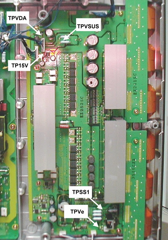
- Check the Scan pulse waveform at TPSC1. (Use TPSS1 of the SS-board to trigger the oscilloscope.)
- Verify the input signals at connector SC2, SC4, SC20 and SC21.
- Verify that the signals of the clock and serial data lines from the D-board are present at connector SC20 and SC21.

SS BOARD

No picture (black Screen) Case-2
No picture (black Screen) Case-2
- The use of a magnifying glass can help localize the defective printed circuit board. Use the magnifying glass to take a close look at the pixels of the screen.
- If the pixels are faintly lit, the defect is most likely located in one of the following boards:
SS2-Board
S3-Board
- Check the status of the LED located on the SS-Board; if the LED is dark, a malfunction of the SS-Board is suspected.
- Listen to the buzz noise of the SS-board. If the buzz noise is not present, a malfunction of the SS-Board is suspected.
- Verify the input signals at connector SS3 and SS1.
- Check the Scan pulse waveform at TPSC1 of the SC-Board. (Use TPSS1 of the SS board to trigger the oscilloscope.)
- Proceed to check the power sources at connector SS11, SS12 and SS33.
- Verify that the clock and serial data lines from the D board are present at connector SS33.

HORIZONTAL BACK BAR [COMPLETELY DARK]
The use of
a magnifying glass can help localize
the defective printed circuit board. Use the magnifying glass to take a close
look at the pixels in
the area of the black bar.
- If the pixels are totally dark, the defect is most likely located in one of the following boards
SU Board
(upper half of the screen only)
SD Board
(lower half of the screen only)
- If the pixels are dimly lit, the defect is most likely located in one of the following boards
SS2 Board
(upper half of the screen only)
SS3 Board
(lower half of the screen only)

PANASONIC PLASMA - TH-42PHD5 - TH-50PHD5 - TH-42PHW5 - TH50PHW5 - TROUBLESHOOTING - AFTER IMAGE PREVENTION - OPTION SETTING
VERTICAL BLACK BAR
- Since the C2 board contains the serial to parallel converters for the picture data that drive this portion of the screen; the most likely cause for this defect can be localized to the C2-Board or the D2-Board.
DEFECT-1

DEFECT-2

- Symptom: No OSD but it has video: Check signal on the D1 board.
Symptom: Burned image (pattern)
is visible. Activate the scroll bar or
run the set with a white raster for at least fifteen minutes.

AFTER IMAGE PREVENTION
Screen Saver Feature
The
Screensaver feature may repair after image damage.
- Press the Setup button on the remote control.
- Use the Up/Down arrow buttons on the remote to highlight screensaver, then press the center button. Use the Up/Down arrow buttons to highlight the function. Use the Left/Right Arrow buttons to change the setting. Negative causes the image to invert, white areas become dark and vice versa. White bar scroll causes a white bar to appear and scroll across the screen continuously. Select White bar scroll, then use the arrow down button and then change the mode to ON.
- Once the mode is ON the menu will disappear and the scrolling bar will appear. Let the Scrolling bar screensaver run for at least 15 minutes if you are attempting to remove an after image problem.


- To stop the screen saver, press the R button on the remote control.
OPTION SETTING
- Press to display the Setup menu.
- Press to select OSD Language.
- Press the surround button on remote control for more than three seconds. The action menu should be displayed on screen.
- Use the Up/Down buttons to select the desired item.
- Use the Left / Right Buttons to select the desired function. The option menu will disappear 60 seconds after the operation.
- Press the R button to exit the Option Menu.
Hidden Option Menu for GPH5D series
GPH5D
chassis series have special function and operation setting facility that is called
“Option Menu”. This Option Menu is useful for special functions that are required
by certain customers. This should be set at the installation stage. The end
user could not set or change these because the optional On Screen menu is hidden
and accessible via the CAT-mode only.
Option menus
|
Default setting
|
Contents
|
Wobbling
|
Off
|
Wobbling
operation On/Off.
The
outline of burnt image will be blurred by intermittent image shift.
|
Off-timer
function
|
Enable
|
Off-timer
operation Enable/Disable.
|
On
Screen display
|
Off
|
Enable/Disable
to display input mode indication after power on and no signal indication.
|
Input
Initial
|
Off
|
Sets the
initial input mode when the power is turned on. Allow input mode selection
while power is on.
|
Initial
VOL. level
|
Sets the
initial volume level when the power is turned on. Allow Volume control while
power is on.
|
|
Maximum
VOL. Level
|
Off
|
Sets the
maximum volume to desired level. Volume cannot exceed this level.
|
INPUT
lock
|
Off
|
Fixes
the input mode to AV, Component/RGB or PC. Cannot change input mode by input selection
key.
|
Button
lock
|
Off
|
Enable/Disable
front operation buttons (Input and/or volume up/down)
|
Studio
W/B
|
Off
|
Set warm
mode color temperature to 3,200
Kelvin.
|
Remote
control User Level
|
Off
|
Remote
key invalidation
Off: All
keys of the remote are valid.
User1:
The keys that are Valid are: Stand-by (ON/OFF), Input, Status, Surround,
Sound
mute
On/Off, and volume adjustment.
User2:
The key that is Valid is only the Standby (ON/OFF).
|
Setting
the remote control User Level and Remote ID off.
- Access service mode (CAT-mode) and press SET UP key on remote.
- Access the hidden option menu.
- Change the remote control User Level and/ or Remote ID set to off. menu is hidden and accessible via the CAT-mode only.