 KDF-46E2010
RM-YD010 MEXICO
KDF-46E2010
RM-YD010 MEXICO
KDF-50E2000 RM-YD010 US-CND
KDF-50E2010 RM-YD010 MEXICO
KDF-55E2000 RM-YD010 US-CND
KDF-55E2010 RM-YD010 MEXICO
American TV standard, NTSC
ATSC Compliant 8VSB, ATSC (8VSB terrestrial)
ANSI/SCTE 07 2000, QAM on cable
Lamp: 100W, XL-2400 Ultra High Pressure Lamp
Projection System: 3 LCD Panels, 1 lens projection system
Screen Size (measured diagonally):
46 inches (KDF-46E2000/46E2010 Only)
50 inches (KDF-50E2000/50E2010 Only)
55 inches (KDF-55E2000/55E2010 Only)
The units have a self-diagnostic function. If an error occurs, the POWER/STANDBY will automatically begin to flash. The number of times the LED flashes translates to a probable source of the problem. A definition of the POWER/STANDBY flash indicators is listed in the instruction manual is listed here. If an error symptom is difficult to reproduce use the Remote Commander to display the record that is stored at the internal NVM to specify the cause of the failure.
Diagnostic Test Indicators.
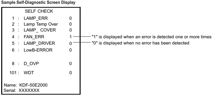
If there is more than one error, the POWER/STANDBY will identify the first of the problem areas. If the errors occur simultaneously, the one that corresponds to the fewest flashes is identified first. Results for all of the diagnostic items are displayed on screen.
(No error has occurred if the screen displays a “0”.)

RELEASING THE POWER/STANDBY LED FLASH.
Unplug the power cord from the outlet to temporarily stop the POWER/STANDBY lamp from flashing.
Self-Diagnostic Screen Display.
For failures that are difficult to reproduce, or accompany occasional power off and/or picture mute, the Self-Diagnostic screen display is useful to specify the cause.
VIEWING THE SELF-DIAGNOSTIC SCREEN.
1. TV must be in standby mode. (Power off).
2. Press the following buttons on the Remote Commander within a second of each other:
DISPLAY > Channel 5 > Volume (-) > POWER
NOTE: This differs from the method of accessing service mode which is Volume (+)
To refresh the Self Check menu when all the items are not displayed, press JUMP on the Remote Commander.
3. Proceed to Viewing the Self-Diagnostic Errors.
VIEWING THE SELF-DIAGNOSTIC ERRORS.
The TV MICRO service menu contains a Log category that stores the errors. To view the first error detected, display the SHUTDOWN - LOG1. Adjustment Item of the STATUS category. If other errors are detected, they are stored in the SHUTDOWN - LOG2 Adjustment Item of the STATUS category.
1. TV must be in standby mode. (Power off).
2. Press the following buttons on the Remote Commander within a second of each other:
DISPLAY > Channel 5 > Volume (+) > POWER. (Service Mode)
3. Do one of the following:
a. If the TV MICRO Service Menu is displayed, proceed to the next step.
b. If the TV Micro Service Menu is not displayed, press JUMP on the Remote Commander until the TV MICRO service menu is displayed.
4. Do one of the following:
a. If the STATUS Category is displayed, proceed to the next step.
b. If the STATUS Category is not displayed, press 2 or 5 on the Remote Commander until the STATUS Category is displayed.
5. The SHUTDOWN_LOG1 Adjustment Item is the first item of the STATUS Category and contains the first error the set detected.
6. To view additional errors, press 1 until the SHUTDOWN_LOG2 Adjustment Item is displayed
7. After repairing the errors, procede to clearing the Self-Diagnostic Screen.

CLEARING THE SELF-DIAGNOSTIC SCREEN.
The self-diagnostic results displayed on the screen are not cleared automatically; therefore you should always check the self-diagnostic screen during repairs. When you have completed the repairs, clear the self-diagnostic screen to reset the results to “0”.
(The self-diagnostic function will not be able to detect any subsequent faults after completion of the repairs unless the Self-Diagnostic result display is cleared to reset the results to “0”.)
1. If the Self-Diagnostic screen is already displayed, proceed to step 3. If not, Power off (Set to Standby mode).
2. Press DISPLAY > Channel 5 > Sound Volume (-) > POWER
3. Press Channel 8 > ENT
The status in the upper right corner changes to “WRITE”. When the operation is complete, the status returns to “SERVICE” and the Self-Diagnostic screen is reset.
4. To exit the Self-Diagnostic screen, turn the power off.
SELF-DIAGNOSTIC FUNCTION OPERATION.
2 : temp
When temperature sensor on the S2 board detects high temperature, or I2C line connector (CN6804: G board, CN160: S2 board) is not seated securely, the TV-micro turns off the lamp. When the temperature sensor on the HB board detects high temperature, or I2C line connector (CN3008: B board, CN110: HB board) is not seated securely, the TV-micro turns off the lamp.
3: Lamp cover or Lamp position.
The rib at the back of the lamp cover closes the SW on the T1 board. The lamp closes the SW on the T2 board. It is monitored by the TV micro (Pin150 of IC3002) and turns off the lamp when it is opened.
4: Fan error
Fan rotation is detected by “FAN-PROT” and the TV micro (Pin 137 of IC3002) turns off the lamp when it is “high”
5: Lamp driver
When the “LAMP-PROT” (Pin 151 IC3002) is high, the lamp is not turned on. If the “LAMP-HV-DET” (Pin 152 IC3002) is low at the same time, it is classified as no high voltage of the lamp driver.
6: Low B LVP
When no B-10.5V is detected, pin 129 of the TV micro is low and it turns off the main power.
8: Low B OVP
When overvoltage of B-10.5V is detected, pin 126 of the TV micro is low and it turns off the main power.
LAMP: Lamp
When the “LAMP-PROT” (Pin 151 of IC3002) (normally at 0V) is high (5V), the self-diagnosis detects the problem and puts the set into Lamp protect mode and turns the lamp off.
If the “LAMP-HV-DET” (Pin 152 of IC3002) is high, at the same time, it’s classified as no lamp of burned out lamp.
G Board (Power supply board: schematic)


Component side and conductor side (Power Board).


How to remove the G-Board.
1 Remove 2 screws to release the Left Stay.
2 Disconnect CN8400 from U Board.
3
Disconnect CN2500 from K Board.
4 Release wires from purse locks.
5 Gently pull chassis out towards the right of the TV to access connectors on B Block Assembly.
6 Disconnect CN308 and CN3750 on B Block Assembly.
7 Release connectors from Wire Holders.
8 Remove 4 screws to release the G Board.
9 Remove 6 screws to detach Metal Shield from G Board.

Using the picture above as a reference, disconnect CN6018, CN6801, CN6804, CN6803, CN6800, CN6805, CN6900, CN6901, CN6009, CN6002, CN6904, and CN6010.

How to remove lamp assembly.
Remove the Lamp door and Lamp before removing the Lamp Block Assembly.
1 Remove 2 screws to release the Right Stay.
2 Disconnect CN150 T1 Board.
3 Disconnect CN155 T2 Board.
4 Disconnect the Thermal Fuse connector.
5 Disconnect CN160 S2 Board.
6 Remove 2 screws then pull out the fan cover.
7 Turn the fan cover over to remove the T1 Board and S2 Board.
8 Remove the LVDS cable and 2 screws.
9 Remove 2 screws to release the Lamp Block Assembly and the Optical Block assembly from the cabinet.
10 Gently pull the Lamp Block Assembly and the Optical Block Assembly out of the cabinet.
11 Turn the assemblies around 180 degrees and release the high voltage lead from the purse lock.
