REPAIRING AND NOT THROWING AWAY

Richtige Fernseher haben Röhren!

Richtige Fernseher haben Röhren!

In Brief: On this site you will find pictures and technical information about Service Modes, Circuit Diagrams, Firmware Update procedure, Disassemble procedure, Universal remote control set-up codes, Troubleshooting and more....

If you go into the profession, you will obtain or have access to a variety of tech tips databases HERE IT IS Master Electronics Repair !.

These are an excellent investment where the saying: 'time-is-money' rules. However, to learn, you need to develop a general troubleshooting approach - a logical, methodical, method of narrowing down the problem. A tech tip database might suggest: 'Replace C536' for a particular symptom. This is good advice for a specific problem on one model. However, what you really want to understand is why C536 was the cause and how to pinpoint the culprit in general even if you don't have a service manual or schematic and your tech tip database doesn't have an entry for your sick TV or VCR.

While schematics are nice, you won't always have them or be able to justify the purchase for a one-of repair. Therefore, in many cases, some reverse engineering will be necessary. The time will be well spent since even if you don't see another instance of the same model in your entire lifetime, you will have learned something in the process that can be applied to other equipment problems.
As always, when you get stuck, checking out a tech-tips database may quickly identify your problem and solution.In that case, you can greatly simplify your troubleshooting or at least confirm a diagnosis before ordering parts.

Happy repairing!
Today, the West is headed for the abyss. For the ultimate fate of our disposable society is for that society itself to be disposed of. And this will happen sooner, rather than later.

How to use the site:

- If you landed here via any Search Engine, you will get what you searched for and you can search more using the search this blog feature provided by Google. You can visit more posts scrolling the left blog archive of all posts of the month/year,
or you can click on the main photo-page to start from the main page. Doing so it starts from the most recent post to the older post simple clicking on the Older Post button on the bottom of each page after reading , post after post.

You can even visit all posts, time to time, when reaching the bottom end of each page and click on the Older Post button.

- If you arrived here at the main page via bookmark you can visit all the site scrolling the left blog archive of all posts of the month/year pointing were you want , or more simple You can even visit all blog posts, from newer to older, clicking at the end of each bottom page on the Older Post button.
So you can see all the blog/site content surfing all pages in it.

- The search this blog feature provided by Google is a real search engine. If you're pointing particular things it will search IT for you; or you can place a brand name in the search query at your choice and visit all results page by page. It's useful since the content of the site is very large.

Note that if you don't find what you searched for, try it after a period of time; the site is a never ending job !

..............The bitterness of poor quality is remembered long after the sweetness of todays funny gadgets low price has faded from memory........ . . . . . .....
Don't forget the past, the end of the world is upon us! Pretty soon it will all turn to dust!

©2010, 2011, 2012, 2013, 2014 Frank Sharp - You do not have permission to copy photos and words from this blog, and any content may be never used it for auctions or commercial purposes, however feel free to post anything you see here with a courtesy link back, btw a link to the original post here , is mandatory.
All posts are presented here for informative, historical and educative purposes as applicable within fair use. NOTHING HERE IS FOR SALE !

Showing posts with label CASH-REGISTER. Show all posts

Monday, 18 March 2019

SHARP XE201 / 202 / 212 / 301-061113-1 CASH REGISTER TROUBLESHOOTING - FUSE FAILURE WHEN SOLENOID CABLE TOUCH THE DRAWYER

SHARP CASH REGISTER TROUBLESHOOTING - Fuse failure when Solenoid cable touch the drawyer - XE201 / 202 / 212 / 301-061113-1


FAULT: The fuse blew out when the solenoid cables touched the drawer
 Solenoid cables used to be twisted around the rib inside the lower cabinet. However, it sagged inside the drawer owing to the way it was twisted. The sagging solenoid cables touched the drawer when opening and closing the drawer. In order to avoid this problem, changed the solenoid cable arrangement inside the drawer. The solenoid cables shall be fixed by tie on the rib inside the lower cabinet.
The solenoid cables inside the drawer sagged owing to the variation of the cable fastening method. The solenoid cables touched the rear side of the drawer when opening and closing the drawer.
The fastening method of the solenoid cable at the drawer is as follows:
Before Change:
The solenoid cables were twisted around the front side of the rib of the lower drawer.
After Change:
   The solenoid cables are fixed with a tie to the rear side of the rib inside the lower cabinet.  Pulling the solenoid cables when fixed to the rear side of the rib with a tie not only avoids the cables sagging but gives space between the cables and the drawer.
   Fix the solenoid cables with a tie when replacing the drawers for repairs or maintenance.
BEFORE
The solenoid cables are twisted around the front side of the rib, inside the lower cabinet.
AFTER
Click on pictures to zoom
The cables are fixed with a tie to the rear side of the rib inside the lower cabinet.

HOW TO PROGRAM SHARP CASH REGISTER - XE-A301

HOW TO PROGRAM SHARP CASH REGISTER - XE-A301


PROGRAMMING
Hardware:
  • IBM PC or 100% compatible
  • 24 MB RAM
  • 40 MB free hard disk space.
Operating System:  Microsoft Windows 98/Me/2000/XP
This tool provides the functions indicated below:
Creating settings of the ECR.  You can create settings for the ECR on your PC and send it to the ECR.
Maintaining the settings: You can receive the settings from the ECR, modify them and send them back to the ECR.  The available settings include:
  • Department programming
  • PLU programming
  • Function programming (%, Discount, Total, etc.)
  • Cashier programming
  • Tax programming
  • Other parameters, etc.
  • Creating graphic logo data
  • You can create unique graphic logos such as your store name and send it to the ECR.
GRAPHIC LOGO
Size: 288 dots (w) x 130 dots (h)
Color: black and white
Black Rate
Total black rate: 35% or lower
Local black rate: The black rate of a horizontal dot line is 55% or less.
  1. Start your PC.
  2. Locate the Setup.exe installer program using Windows Explorer and double-click the executable.
  3. Follow the instruction of the Installer program.
The Installer program installs DLL (Dynamic Link Library) files necessary for software execution into the system area. Once the DLL files are installed, you must restart the computer and prior to using the software.
Settings.
You can change the program data of the ECR using one of the three procedures below:
Case A: Programming the settings for the first time.
  • Click [Click here when you start programming at MRS data].
  • Select the item you want to program from the menu, and change the settings on your PC.
  • Select [Send/Save Button] to send the data from PC to ECR.
Case B: Modifying the setting data in ECR
  • Click [Click here when you modify current programming].
  • Select the item you want to modify, and click [from ECR] to receive the data from ECR.
  • Modify the settings on your PC.
  • Select [Send/Save Button] to send the data from PC to ECR.
Case C: Modifying the settings on your PC
  • Click [Click here when you modify current programming].
  • Select the item you want to modify, and click [from your PC] to receive the data from ECR.
  • Modify the settings on your PC.
  • Select [Send/Save Button] to send the data from the PC to the ECR.
Software operation.
The setting screen of the Easy Programming Tool consists of several sub-screens called "Cards." Each card consists of several objects.
Default Screen
Card list
The right-hand button displays a list of the settings available. Select the item you wish to modify and the next screen will appear. You can program items except the DEPT, PLU, and FUNCTION in this screen.
The items of DEPT, PLU, and FUNCTION are listed. Click the item, then the setting screen appears.
Select button
Press this button to select a specific item. After the item is selected, the next screen appears.
Send/Save button
Press this button to send the settings to the ECR or to save the settings on the hard disk.
The basic operation for making program settings is as follows:
Select the item by using the mouse and/or keyboard
à Modify the settings of the selected area
à Press the [Apply Button]
à Select the next item by using the mouse and/or keyboard.
Card Title
This shows the heading of the current program selection.
Apply Button
Press this button to save the data temporarily, which will allow you to go to the next screen after modifying the setting.
Back Button
Press this button to go back to the previous card.
SERIAL COMMUNICATION BETWEEN ECR & PC
Can send and receive the program settings between the ECR and PC through serial communications.
The Hardware requirements for serial communications are as follows:
A personal computer
A RS232C cable
Wiring Diagram for the RS232C Cable

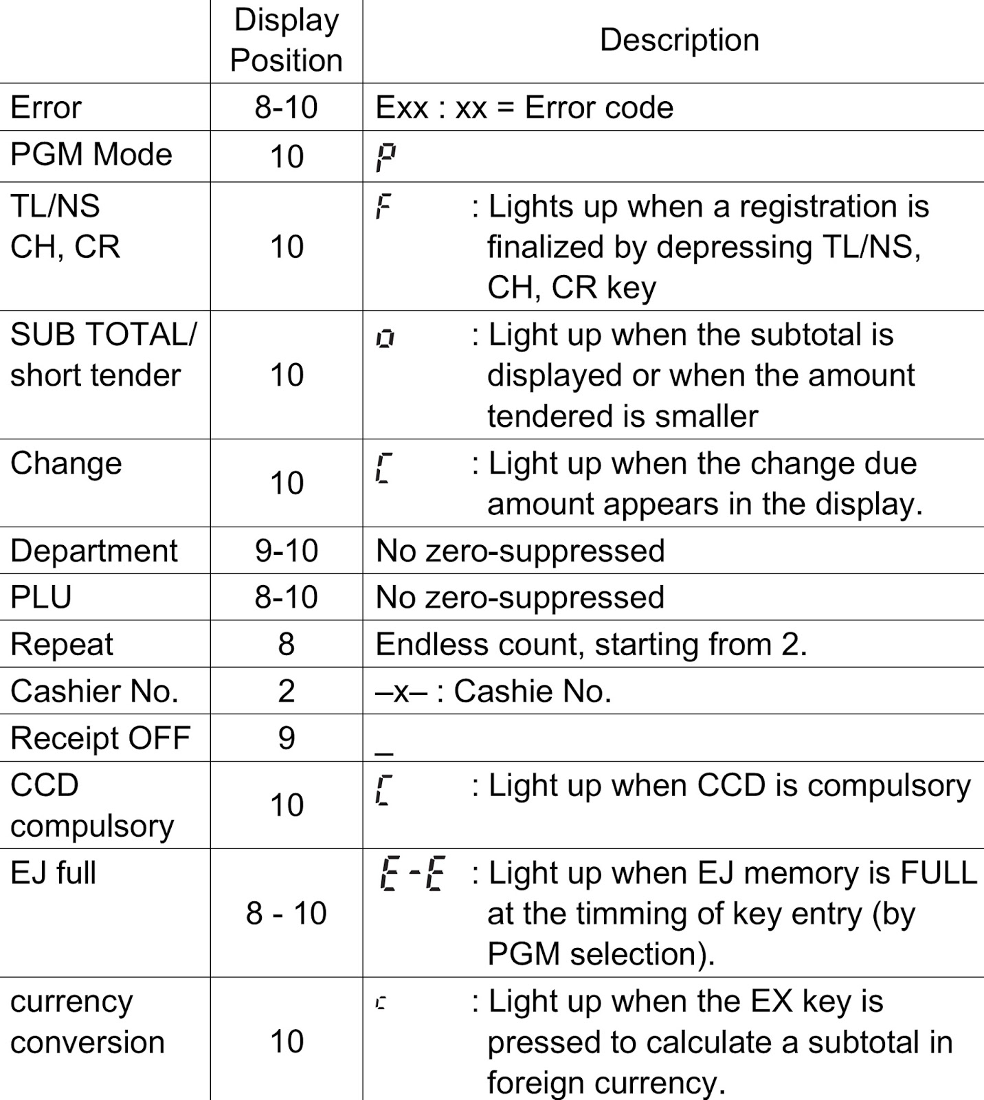
SHARP ERA-220 ELECTRONIC CASH REGISTER - HOW TO ENTER SERVICE MODE - ERROR CODES - RESET - SELF DIAGNOSTIC FUNCTION - POWER SUPPLY SCHEMATIC

SHARP ERA-220 ELECTRONIC CASH REGISTER - HOW TO ENTER SERVICE MODE - ERROR CODES - RESET - SELF DIAGNOSTIC FUNCTION - POWER SUPPLY SCHEMATIC


SERVICE MODE
Before turning the mode switch from the (SRV’) to (SRV), make sure the AC power cord is connected to the wall outlet; otherwise, the data on memory might be destroyed.
SRV. Reset (Program Loop Reset)
Used to return the machine back to its operational state after a lock-up has occurred.
  • Unplug the AC cord from the wall outlet.
  • Set the mode switch to (SRV’) position.
  • Plugin the AC cord to the wall outlet.
  • Turn to (SRV) position from (SRV’) position.
PROGRAM RESET ****
Master reset (All memory clear)
Used to clear all memory contents and return machine back to its initial settings. return keyboard back to default. for default keyboard layout.
  • Unplug the AC cord from the wall outlet.
  • Set the MODE switch to the (SRV’) position.
  • Plugin the AC cord to the wall outlet.
  • While holding down JOURNAL FEED key, turn to (SRV) position from (SRV’) position.
MASTER RESET ****
To start the diagnostic program, you must enter the following command.
3-digit test item number key in the SRV mode
The RAM must be operating properly to go into this mode. This is necessary because the control jumps to the program area in the SRV mode. A master reset must be performed before operating the ECR for the first time. After any option is installed, a program reset is required. When the master reset or program reset is performed, be sure to check the printout on the journal paper.
Master reset : Turn power on in the SRV’ mode and change it to the SRV mode with the PAPER FEED key pressed.
print : MASTER RESET ***
Program reset : Turn power on in the SRV’ mode and change it to the SRV mode.
print : PRG. RESET ***
With the SRV mode and the following test code entry, the test start
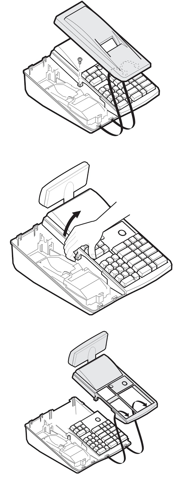
Cautions to be taken when removing the upper cabinet.
When removing the upper cabinet, first remove the printer cover and then remove the upper cabinet from the let side, as shown.
Cautions to be taken when installing the pop-up display connector cable.
Exercise care not to have the wrong direction of the pop-up display connector cable when connecting the cable to the Key I/F connector CN14.
When connecting the cable, make sure:
The cable is not kinked.
The cable contact surface points upward against the PWB when inserting the cable.
MAIN POWER SUPPLY SCHEMATIC
CLICK ON PICTURES TO ZOOM
ERROR CODES

Saturday, 16 March 2019

SHARP ER A410 - ER A420 - HOW TO UPGRADE READ ONLY MEMORY [ROM]

SHARP ER A410 - ER A420 - HOW TO UPGRADE READ ONLY MEMORY [ROM]

ROM A410A 420U
MODEL NAME  :  ER-A410, ER-A420
ROM SIZE    :  512KBytes(4Mbits)
FILE NAME   :  A420U_2B.ROM
ROM VERSION :  28F40RCC2B
CHECK SUM   :  A610
ERA 420 ROM LOADING
Sharp has released a new POSUTILITYTOOLS.exe program.
POSUTILITYTOOLS3.exe is to be used to download the ROM image to the ERA410/20 machine follow the procedure below.
The exe file as well as ROM images can be found on the Sharp Technical Web Site.
Procedure to load image via POSutilitytool3 program:
Put ER-A410/20 into IPL Mode, using the following procedure:
  • Turn off the power switch of ER-A420 and turn modeswitch to SRV position.
  • Holding down Receipt paper feed key, Journal paper feed key and Void key, turn on power switch of ER-420.  "IPL" is shown on operator display.  Then you can load the ROM object to ER-A420 by POS utility tool3 via RS232.
TO UPGRADE THE ERA420 ROM IMAGE
Before working on the installation, unplug the AC code from the AC outlet.
  • Open the top cabinet.
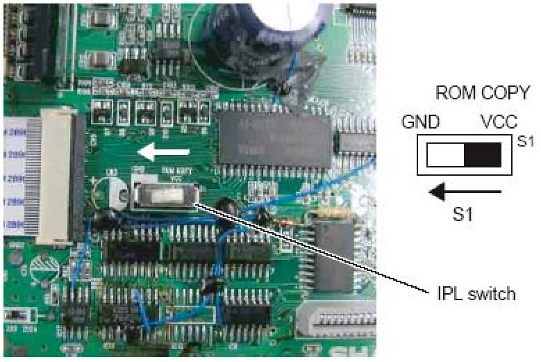
  • Set the IPL switch (S1) to ROM COPY position.
  • Install the IPL ROM to the IC socket of the MAIN PWB.
  • Turn the mode key switch to SRV’ position, and insert AC plug in AC outlet.
  • Turn the mode key switch to SRV position. The IPL procedure is started.
When the procedure is completed, the message of “Completed.” Is shown.
CLICK ON PICTURES TO ZOOM. {Click ß at the top left of the browser to come back.}
  • Unplug the AC code from the AC outlet.
  • Remove the IPL ROM to the IC socket of the MAIN PWB.
  • Set the IPL switch (S1) to GND position.
  • Replace the top cabinet.
  • Perform the master reset.
Turn the mode key switch to the SRV’ position, insert AC plug in AC outlet.  While holding down Journal feed key, turn to SRV position from SRV’ position.

Monday, 4 March 2019

SHARP XE-A106 ELECTRONIC CASH REGISTER – SCHEMATIC - MASTER RESET OR INITIALIZATION PROCEDURE

Sharp XE-A106 ELECTRONIC CASH REGISTER – Schematic - Master Reset or Initialization Procedure

Sharp Cash Register XE A106 - Circuit Diagram - How to Reset  or- Initialize - Test Procedure
Reset Procedure or Initialization
Master reset: Clears all the memory and initializes each preset parameter
1. Turn off the power (Power OFF).
2. Let the ECR be without the memory back up battery.
3. Turn the mode switch to the others of Power-off position.
4. Turn on the power (Power ON). When the master rest is completed, the buzzer sounds intermittently three times.
5. Attach the memory back up battery to the ECR.  The master reset can also be accomplished in the following case.
Power OFF: Means disconnecting the AC power supply to the machine. (Specifically, unplugging the machine.)
Power ON: Means connecting the AC power to the ma-chine. (Specifically, plugging in the machine.)
[In case a power failure occurs when the machine has no battery installed, the master reset operation is automatically performed after the power has been restored.]
MAIN BOARD Schematic
PWB
TEST PROCEDURE
Perform the keyboard check with the sum check data of the key code.
Enter the sum check data of each model in the four digits preceding the diag number 02, and compare the data with the key position code which is added until the “CA/AT/NS” key is pressed.
If the data coincides with the code, the completion print is performed.
If not, the error print is performed.
Completion print 02
Error print - - -02
XXXX Sum data
DISPLAY BUZZER TEST
KEY OPERATION
3 => PO
TEST PROCEDURE
Check the continuous buzzer sound and the display state.
Display state:
8. 7. 6. 5. 4. 3. 2. 1.
The decimal point will shift from the lower digit to the upper, step by step (500mSEC). To cancel the test mode, press any key, and the buzzer will stop and the completion print is performed.
Completion print =>  03
DRAWER TEST
KEY OPERATION
4 => PO
TEST PROCEDURE
The drawer opens with the above key operation. Check that the drawer is open. Press any key to terminate the test.
Completion print =>  04
PRINTER TEST
KEY OPERATION
5 => PO
TEST PROCEDURE
With the above key operation , the print test pattern is repeatedly printed.
Pressing any key will terminate the test after the completion of one cycle print. (The receipt is issued at the end.)
TIME DISPLAY TEST
KEY OPERATION
8 => PO
TEST PROCEDURE
DESTINATION DISPLAY
KEY OPERATION
9 => PO
TEST PROCEDURE
Display the destination code as follows.
Display       0
Display X (X:0
To terminate the test, press any key.
Completion print 09
CPU VERSION NO. PRINT
KEY OPERATION
6 => PO
DESCRIPTION
The CPU version No. are printed with above key operation.
(Print example)
0102           CPU version NO.
06
This test is terminated when printing is completed.
BATTERY VOLTAGE SENSOR TEST
KEY OPERATION
7 => PO TEST PROCEDURE Displays A/D conversion port read value.
0155 or greater : Normal
0154 or smaller : Low battery display
0138 or smaller : No battery display and MSR is done when power on.
To terminate the test, press any key.
Completion print => 07

Thursday, 7 February 2019

SHARP XE-A106 ELECTRONIC CASH REGISTER – SCHEMATIC - MASTER RESET OR INITIALIZATION PROCEDURE

Sharp XE-A106 ELECTRONIC CASH REGISTER – Schematic - Master Reset or Initialization Procedure

Sharp Cash Register XE A106 - Circuit Diagram - How to Reset  or- Initialize - Test Procedure
Reset Procedure or Initialization
Master reset: Clears all the memory and initializes each preset parameter
1. Turn off the power (Power OFF).
2. Let the ECR be without the memory back up battery.
3. Turn the mode switch to the others of Power-off position.
4. Turn on the power (Power ON). When the master rest is completed, the buzzer sounds intermittently three times.
5. Attach the memory back up battery to the ECR.  The master reset can also be accomplished in the following case.
Power OFF: Means disconnecting the AC power supply to the machine. (Specifically, unplugging the machine.)
Power ON: Means connecting the AC power to the ma-chine. (Specifically, plugging in the machine.)
[In case a power failure occurs when the machine has no battery installed, the master reset operation is automatically performed after the power has been restored.]
MAIN BOARD Schematic
PWB
TEST PROCEDURE
Perform the keyboard check with the sum check data of the key code.
Enter the sum check data of each model in the four digits preceding the diag number 02, and compare the data with the key position code which is added until the “CA/AT/NS” key is pressed.
If the data coincides with the code, the completion print is performed.
If not, the error print is performed.
Completion print 02
Error print - - -02
XXXX Sum data
DISPLAY BUZZER TEST
KEY OPERATION
3 => PO
TEST PROCEDURE
Check the continuous buzzer sound and the display state.
Display state:
8. 7. 6. 5. 4. 3. 2. 1.
The decimal point will shift from the lower digit to the upper, step by step (500mSEC). To cancel the test mode, press any key, and the buzzer will stop and the completion print is performed.
Completion print =>  03
DRAWER TEST
KEY OPERATION
4 => PO
TEST PROCEDURE
The drawer opens with the above key operation. Check that the drawer is open. Press any key to terminate the test.
Completion print =>  04
PRINTER TEST
KEY OPERATION
5 => PO
TEST PROCEDURE
With the above key operation , the print test pattern is repeatedly printed.
Pressing any key will terminate the test after the completion of one cycle print. (The receipt is issued at the end.)
TIME DISPLAY TEST
KEY OPERATION
8 => PO
TEST PROCEDURE
DESTINATION DISPLAY
KEY OPERATION
9 => PO
TEST PROCEDURE
Display the destination code as follows.
Display       0
Display X (X:0
To terminate the test, press any key.
Completion print 09
CPU VERSION NO. PRINT
KEY OPERATION
6 => PO
DESCRIPTION
The CPU version No. are printed with above key operation.
(Print example)
0102           CPU version NO.
06
This test is terminated when printing is completed.
BATTERY VOLTAGE SENSOR TEST
KEY OPERATION
7 => PO TEST PROCEDURE Displays A/D conversion port read value.
0155 or greater : Normal
0154 or smaller : Low battery display
0138 or smaller : No battery display and MSR is done when power on.
To terminate the test, press any key.
Completion print => 07