REPAIRING AND NOT THROWING AWAY

Richtige Fernseher haben Röhren!

Richtige Fernseher haben Röhren!

In Brief: On this site you will find pictures and technical information about Service Modes, Circuit Diagrams, Firmware Update procedure, Disassemble procedure, Universal remote control set-up codes, Troubleshooting and more....

If you go into the profession, you will obtain or have access to a variety of tech tips databases HERE IT IS Master Electronics Repair !.

These are an excellent investment where the saying: 'time-is-money' rules. However, to learn, you need to develop a general troubleshooting approach - a logical, methodical, method of narrowing down the problem. A tech tip database might suggest: 'Replace C536' for a particular symptom. This is good advice for a specific problem on one model. However, what you really want to understand is why C536 was the cause and how to pinpoint the culprit in general even if you don't have a service manual or schematic and your tech tip database doesn't have an entry for your sick TV or VCR.

While schematics are nice, you won't always have them or be able to justify the purchase for a one-of repair. Therefore, in many cases, some reverse engineering will be necessary. The time will be well spent since even if you don't see another instance of the same model in your entire lifetime, you will have learned something in the process that can be applied to other equipment problems.
As always, when you get stuck, checking out a tech-tips database may quickly identify your problem and solution.In that case, you can greatly simplify your troubleshooting or at least confirm a diagnosis before ordering parts.

Happy repairing!
Today, the West is headed for the abyss. For the ultimate fate of our disposable society is for that society itself to be disposed of. And this will happen sooner, rather than later.

How to use the site:

- If you landed here via any Search Engine, you will get what you searched for and you can search more using the search this blog feature provided by Google. You can visit more posts scrolling the left blog archive of all posts of the month/year,
or you can click on the main photo-page to start from the main page. Doing so it starts from the most recent post to the older post simple clicking on the Older Post button on the bottom of each page after reading , post after post.

You can even visit all posts, time to time, when reaching the bottom end of each page and click on the Older Post button.

- If you arrived here at the main page via bookmark you can visit all the site scrolling the left blog archive of all posts of the month/year pointing were you want , or more simple You can even visit all blog posts, from newer to older, clicking at the end of each bottom page on the Older Post button.
So you can see all the blog/site content surfing all pages in it.

- The search this blog feature provided by Google is a real search engine. If you're pointing particular things it will search IT for you; or you can place a brand name in the search query at your choice and visit all results page by page. It's useful since the content of the site is very large.

Note that if you don't find what you searched for, try it after a period of time; the site is a never ending job !

..............The bitterness of poor quality is remembered long after the sweetness of todays funny gadgets low price has faded from memory........ . . . . . .....
Don't forget the past, the end of the world is upon us! Pretty soon it will all turn to dust!

©2010, 2011, 2012, 2013, 2014 Frank Sharp - You do not have permission to copy photos and words from this blog, and any content may be never used it for auctions or commercial purposes, however feel free to post anything you see here with a courtesy link back, btw a link to the original post here , is mandatory.
All posts are presented here for informative, historical and educative purposes as applicable within fair use. NOTHING HERE IS FOR SALE !

Showing posts with label COMPAQ. Show all posts

Monday, 8 April 2019

COMPAQ PRESARIO CQ42 – DISASSEMBLING PROCEDURE – HOW TO REPLACE THE KEYBOARD

Compaq Presario CQ42 – Disassembling procedure – How to replace the keyboard


HP G42 Notebook PC  - Compaq Presario CQ42 – Disassembling procedure – How to replace the keyboard – How to remove the WLAN – How to remove the optical drive and HDD
HP G42 Notebook PC  - Compaq Presario CQ42:  DISASSEMBLING PROCEDURE 
How to remove Battery
Before disassembling the computer, follow these steps:
1. Shut down the computer. If you are unsure whether the computer is off or in Hibernation, turn the computer on, and then shut it down through the operating system.
2. Disconnect all external devices connected to the computer.
3. Disconnect the power from the computer by first unplugging the power cord from the AC outlet and then unplugging the AC adapter from the computer.
Remove the battery:
1. Turn the computer upside down on a flat surface.
2. Slide the battery release latch (1) to release the battery.
3. Pivot the battery (2) upward and lift it out of the computer (3).
To insert the battery, insert the rear edge of the battery into the battery bay and pivot the front edge downward until the battery is seated. The battery release latch automatically locks the battery into place.
How to remove Hard drive
Before removing the hard drive, follow these steps:
1. Shut down the computer. If you are unsure whether the computer is off or in Hibernation, turn the computer on, and then shut it down through the operating system.
2. Disconnect all external devices connected to the computer.
3. Disconnect the power from the computer by first unplugging the power cord from the AC outlet and then unplugging the AC adapter from the computer.
4. Remove the battery
Remove the hard drive:
1. Position the computer with the front toward you.
2. Remove the two Phillips PM2.5×5.0 screws (1) that secure the hard drive cover to the computer.
3. Lift the left side of the hard drive cover (2), swing it forward, and remove the cover (3). The hard drive cover is included in the plastics kit, spare part number 600190-001.
4. Remove the three Phillips PM2.5×4.0 screws (1) that secure the hard drive to the computer.
5. Use the hard drive bracket to lift the hard drive out (2) of the hard drive compartment.
6. Disconnect the hard drive cable from the system board.
How to remove Optical drive
Before removing the optical drive, follow these steps:
1. Shut down the computer. If you are unsure whether the computer is off or in Hibernation, turn the computer on, and then shut it down through the operating system.
2. Disconnect all external devices connected to the computer.
3. Disconnect the power from the computer by first unplugging the power cord from the AC outlet and then unplugging the AC adapter from the computer.
4. Remove the battery
Remove the optical drive:
1. Position the computer upside down with the front toward you.
2. Remove the Phillips PM2.5x5.0 screw (1) that secures the optical drive to the computer.
3. Insert a flat-bladed screwdriver or similar tool into the access point through the hard drive compartment (2), and then push the drive bracket to the left to release the optical drive.
4. Remove the optical drive (3).
How to remove WLAN module
Before removing the WLAN module, follow these steps:
1. Shut down the computer. If you are unsure whether the computer is off or in Hibernation, turn the computer on, and then shut it down through the operating system.
2. Disconnect all external devices connected to the computer.
3. Disconnect the power from the computer by first unplugging the power cord from the AC outlet and then unplugging the AC adapter from the computer.
4. Remove the battery
5. Remove the hard drive cover
Remove the WLAN module:
1. Turn the computer upside down with the front toward you.
2. Loosen the 2 Phillips PM2.5×5.0 captive screws (1) that secure the mini-card compartment cover.
3. Lift the cover off the computer (2). The mini-card compartment cover is included in the plastics kit, spare part number 600190-001.
4. Disconnect the two WLAN antenna cables (1) from the WLAN module.
5. Remove the Phillips PM2.0×3.0 screw (2) that secures the WLAN module to the computer. (The edge of the module opposite the slot rises away from the computer.)
6. Remove the WLAN module (3) by pulling it away from the slot at an angle.
How to remove Keyboard
Before removing the keyboard, follow these steps:
1. Shut down the computer. If you are unsure whether the computer is off or in Hibernation, turn the computer on, and then shut it down through the operating system.
2. Disconnect all external devices connected to the computer.
3. Disconnect the power from the computer by first unplugging the power cord from the AC outlet and then unplugging the AC adapter from the computer.
4. Remove the battery
5. Remove the hard drive
6. Remove the mini-card compartment cover
Remove the keyboard:
1. Turn the computer upside down with the front toward you.
2. Remove the six Phillips PM2.5×6.5 screws that secure the keyboard to the computer.
3. Turn the computer display-side up with the front toward you.
4. Open the computer as far as possible.
5. Release the top edge of the keyboard by lifting it up to disengage the keyboard from the tabs on the top cover (1).
6. Slide the top edge of the keyboard back (2) until it rests against the display.
7. Release the zero insertion force (ZIF) connector (1) to which the keyboard cable is attached and disconnect the keyboard cable (2) from the system board.

Wednesday, 3 April 2019

HP COMPAQ NOTEBOOK NC4000 SERIES KEYBOARD REPLACEMENT- (USER REPAIRABLE)

KEYBOARD REPLACEMENT- HP Compaq Notebook nc4000 Series (User Repairable)

Prepare to replace the Keyboard:
Turn off the notebook.
Disconnect the AC adapter and all external devices.
Remove the battery pack by following these steps:
a. Turn the notebook bottom side up with the front facing forward.
b. Slide and hold the battery release latch [1] to the left. The rear edge of the battery pack releases from the notebook.
c. Lift the rear edge of the battery pack up and swing it forward [2].
d. Remove the battery pack.
LED switch cover removal
Close the notebook and turn it bottom side up with the rear panel facing forward.
Remove the two T8M2.0×8.0 screws that secure the LED switch cover to the notebook.
Turn the notebook topside up with the front facing forward.
Open the notebook as far as it will open.
Press down on the (esc) key 1 to reveal the notch 2 in the left side of the LED switch cover.
Insert a flat-bladed tool into the notch and lift the left side of the LED switch cover 3.
After the left side of the LED switch cover has disengaged from the notebook, swing the LED switch cover up and to the right.
Remove the LED switch cover.
Close the notebook and turn it bottom side up with the rear panel facing forward.
Remove the T8M2.0×8.0 screw that secures the keyboard to the notebook.

Turn the notebook topside up with the front facing forward.
Open the notebook as far as it will open.
Lift the rear edge of the keyboard 1.
Slide the keyboard toward the display 2 until the notches on the front edge of the keyboard clear the top cover.
Swing the front edge of the keyboard up and back 3 until it rests on the display.
Release the zero insertion force (ZIF) connector 1 to which the pointing stick cable is attached and disconnect the pointing stick cable 2 from the system board.
Release the ZIF connector 3 to which the keyboard cable is attached and disconnect the keyboard cable 4 from the system board.
Remove the keyboard.
Reverse the above procedure to install the keyboard.

Tuesday, 2 April 2019

COMPAQ PRESARIO 1800 - 1800T SERIES - HOW TO CLEAR POWER-ON PASSWORD

COMPAQ PRESARIO 1800 - 1800T SERIES - HOW TO CLEAR POWER-ON PASSWORD

Presario 1800/1800T Series (Models: XL280, XL380, XL381, and XL390) Keyboard Removal
PASSWORD RESET
If you do not know the Power-on password, clear it by performing the following steps:
1. Turn off the Notebook.
2. Disconnect the power cord.
3. Remove the battery.
4. Remove the Palm rest cover.
5. Remove the keyboard.
6. Remove the heat sink.
7. Locate the CMOS switch to the right of the CD/DVD drive on the system board.
8. Slide the black switch to the right {1} holding it in this position for at least 15 seconds to ensure that the password is cleared.
Reassemble the Notebook.
Turn on the Notebook to verify that the Power-on password has been cleared. If it has not been cleared, repeat this procedure.
KEYBOARD REMOVAL
Palm rest Cover with Touch-pad
It is not necessary to remove the display panel assembly to access the interior components of the Notebook.
To remove the Palm rest cover with Touch pad, complete the following steps:
1. Prepare the Notebook for dis-assembly.
2. Close the display and turn the Notebook upside down.
3. Remove four screws from the bottom of the Notebook, and one from the battery compartment.
4. Turn the Notebook right side up and open the display.
5. Lift up the front end of the Palm rest cover.  Note: It may be necessary to apply pressure on the sides of the Palm rest cover to release it from the chassis.
6. Disconnect the flex cable from the ZIF [Zero Insertion Force] Connection the Display module.

Gently lift the front of the keyboard, disconnect the flex cable from the ZIF Connector on the system board, and remove the keyboard.

Thursday, 21 March 2019

HP COMPAQ PRESARIO V5000 NOTEBOOK PC - DISASSEMBLE PROCEDURE - DISPLAY ASSEMBLY DETAILS - COMPONENTS

 HP COMPAQ PRESARIO V5000 NOTEBOOK PC - DISASSEMBLE PROCEDURE


DISASSEMBLY
  • Report the computer serial number to HP when requesting information or ordering spare parts. The serial number is located on the bottom of the computer.

DISASSEMBLY SEQUENCE CHART
PREPARING FOR DISASSEMBLY
  • Shut down the computer. If you are unsure whether the computer is off or in hibernation, turn the computer on, and then shut it down through the operating system.
  • Disconnect all external devices connected to the computer.
  • Disconnect the power cord.
Battery Pack Spare Part Number Information
  • 12-cell, 8.8-Amp hour à 407835-001
  • 6-cell, 4.0-Amp hour à 407834-001
Remove the battery pack by following these steps:
  • Turn the computer upside down with the front toward you.
  • Slide the battery pack release latch [1] to the left. (The battery pack disengages from the computer.)
  • Lift the front edge of the battery pack [2] and swing it back to remove it.
HARD DRIVE
Spare part number information
5400 rpm, 100-GB
5400 rpm, 80-GB
5400 rpm, 60-GB
5400 rpm, 40-GB
409064-001
409063-001
409062-001
409061-001
  • Prepare the computer for disassembly.
  • Loosen the two Phillips PM2.5×5.0 captive screws [1] that secure the hard drive cover to the computer.
  • Lift the rear edge of the hard drive cover [2] , and then swing it up and forward and remove it.
  • Slide the hard drive [1] to the right, and then lift the hard drive [2] from the hard drive bay.
  • Remove the four Phillips PM3.0×4.0 hard drive frame screws [1] that secure the hard drive frame to the hard drive.
  • Slide the hard drive [2] away from the hard drive to remove it.
COMPUTER FEET
  • The computer feet are adhesive-backed rubber pads. The feet are included in the Plastics Kit, spare part number (415691-001.)
  • There are two additional computer feet that are installed on the 12-cell battery pack. These additional feet are not depicted in the following image.
MEMORY MODULE [1 DIMM]
Spare part number.

PC2-5300
1024 MB
512 MB
256 MB

409060-001
409059-001
409058-001
PC2-4200
1024 MB
512 MB
256 MB

407767-001
407766-001
407765-001
  • Loosen the Phillips PM2.5×5.0 captive screw [1] that secures the memory/Mini Card module compartment cover to the computer.
  • Lift the right side of the cover [2] and swing it up and to the left and remove it.  [The memory/Mini Card module compartment cover is included in the Plastics Kit, spare part number 415691-001]
  • Spread the retaining tabs [1] on each side of the memory module socket to release the memory module. (The edge of the module opposite the socket rises away from the computer.)
  • Remove the memory module by pulling the module away from the socket at an angle [2]. [Memory modules are designed with notches [3] to prevent incorrect installation into the memory module socket.]
MINI CARD MODULE
Before disconnecting the antenna cables, make note of which cable is attached to which antenna clip on the Mini Card communications card.
  • Disconnect the auxiliary and main [1] antenna cables from the Mini Card communications module.
  • Slide the retaining bar [2] forward. (The edge of the module opposite the socket rises away from the computer.)
  • Remove the Mini Card communications module by pulling the module away from the socket at an angle [3].

Mini Card communications modules are designed with notches [4] to prevent incorrect installation into the Mini Card module socket.
OPTICAL DRIVE [SPARE PARTS]
  1. DVD±RW and CD-RW Double Layer Combo Drive with LightScribe and HLDS à 417699-001
  2. DVD±RW and CD-RW Double Layer Combo Drive with LightScribe à 413102-001
  3. DVD/CD-RW Double Layer Combo Drive with LightScribe DVD/CD-RW Combo Drive à 413101-001 _ 413100-001.
  • Remove the Phillips PM2.5×5.0 screw [1] that secures the optical drive to the computer.
  • Insert a thin tool into the notch [2] on the back of the optical drive and push to disconnect the optical drive from the system board.
  • Remove the optical drive [3].

  • If it is necessary to replace the optical drive bracket, perform the following steps:
  • Position the optical drive with the connector toward you.
  • Remove the two Phillips PM2.0×4.0 screws [1] that secure the optical drive bracket to the optical drive.
  • Remove the optical drive bracket [2].
SWITCH COVER
  • Remove the two Phillips PM2.5×5.0 screws that secure the switch cover to the computer.
  • Turn the computer display-side up with the front toward you.
  • Open the computer as far as possible.
  • Insert a flat-bladed tool into the switch cover notches behind the f1, f5, f11, and insert keys [1] and lift up until the switch cover [2] disengages from the computer.
  • Remove the switch cover.
KEYBOARD SPARE PART INFORMATION
  • Remove the four Phillips PM2.5×5.0 screws [1] that secure the keyboard to the computer.
  • Lift the rear edge of the keyboard [2] to release it from the top cover.

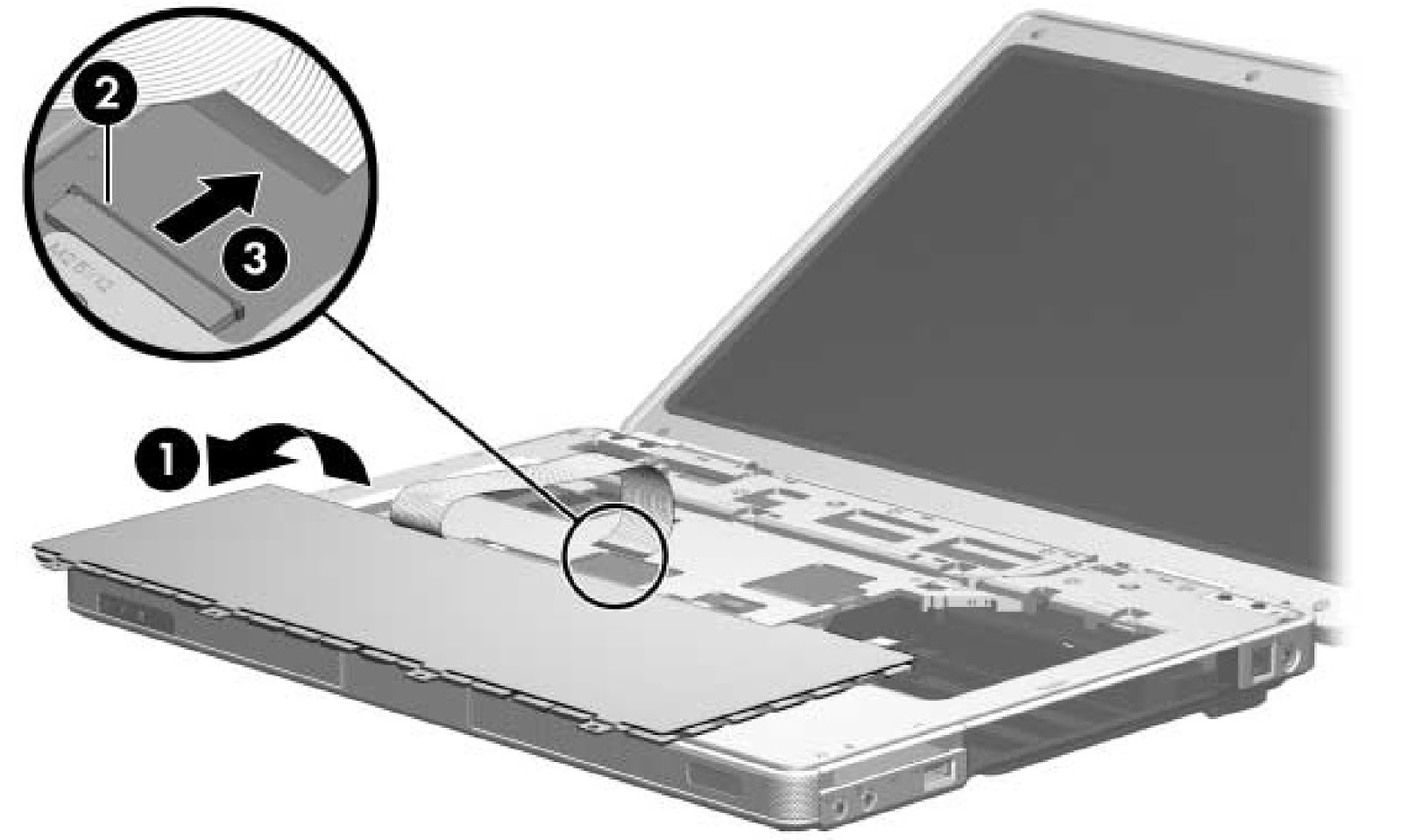
  • Swing the keyboard [1] forward until it rests on the palm rest.
  • Release the zero insertion force (ZIF) connector to which the keyboard cable [2] is attached and disconnect the keyboard cable [3].
  • Remove the keyboard assembly.
DISPLAY ASSEMBLY
All display assemblies include a display cable, wireless antenna transceivers, and antenna cables.
15.4-inch, WXGA with BrightView à 407842-001
15.4-inch, WXGA antiglare à 407840-001
  • Before disconnecting the antenna cables, make note of which cable is attached to which antenna clip on the Mini Card communications card.
  • Disconnect the auxiliary and main wireless antenna cables [1] from the Mini Card module.
  • Remove the two Phillips PM2.5×13.0 screws [2] that secure the display assembly to the computer.
  • Disconnect the display cable [1] from the system board.
  • Remove the wireless antenna cables from the clips [2] in the top cover.
CAUTION: Support the display assembly when removing the following screws. Failure to support the display assembly can result in damage to the display assembly and other computer components.
  • Remove the four Phillips PM2.5×9.0 screws [1] that secure the display assembly to the computer.
  • Lift the display assembly straight up and remove it [2].

HP COMPAQ PRESARIO V5000 NOTEBOOK PC - DISPLAY ASSEMBLY DETAILS - COMPONENTS


DISPLAY ASSEMBLY COMPONENTS
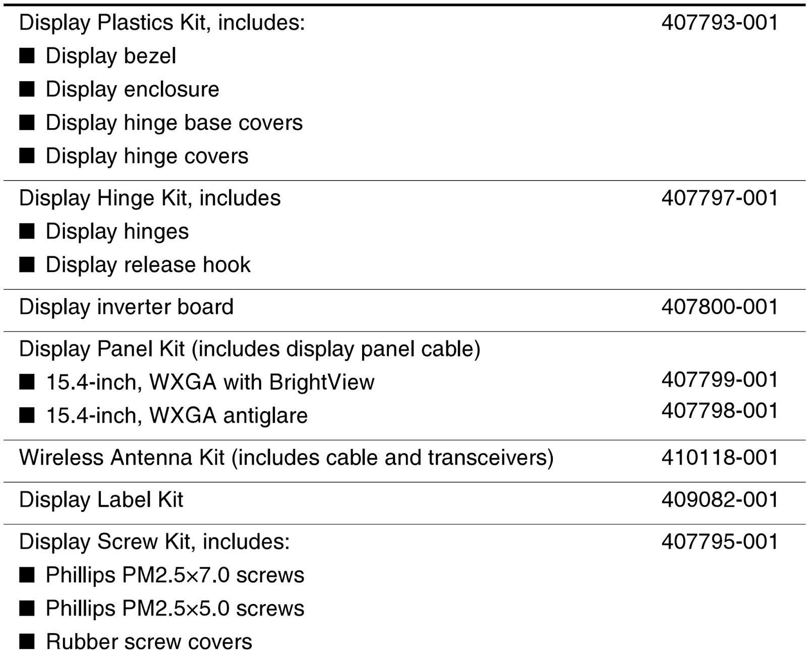
  • Remove the six rubber screw covers  [1] and [2] and the six Phillips PM2.5×7.0 screws [3] that secure the display bezel to the display assembly.  The rubber screw covers are available in the Display Screw Kit, spare part number 407795-001
  • The four-rubber screw covers [1] on top edge of the display bezel is a different size and shape than the two rubber screw covers [2] on the bottom edge of the display bezel.
  • The display bezel and display enclosure are available in the Display Plastics Kit, spare part number 407793-001.
  • Flex the inside edges of the left and right sides [1] and the top and bottom sides [2] of the display bezel until the bezel disengages from the display enclosure.
  • Remove the display bezel [3].
  • Disconnect the display panel cable [1] and display backlight cable [2] from the display inverter board.
  • The display hinge base covers are available in the Display Plastics Kit, spare part number 407793-001.
  • If is necessary to replace the display hinge base covers, remove the two Phillips PM2.5×5.0 screws [1] that secure the covers to the display enclosure.
  • Remove the display hinge base covers [2].
  •  Remove the four Phillips PM2.5×5.0 screws [1] that secure the display panel and inverter board to the display enclosure.
  • Remove the display panel [2] and inverter board [3].
The display hinge covers are available in the Display Plastics Kit, spare part number 407793-001.
  • If it is necessary to replace either of the display hinge covers, detach the display hinge cover clips [1] from the display hinge.
  • Swing the display hinge cover [2] back until it clears the display hinge.
  • Slide the hinge cover [3] off of the display hinge.
The display release hook is available in the Display Hinge Kit, spare part number 407797-001.
  • If it is necessary to replace the display release hook, remove the two PM2.5×5.0 screws [1] that secure the hook to the display enclosure.
  • Remove the display release hook [2].
The display hinges are available in the Display Hinge Kit, spare part number 407797-001.
  • If it is necessary to replace the display hinges, remove the four Phillips PM2.0×4.0 screws [1] that secure each hinge to the display panel.
  • Remove the display hinges [2].
The wireless antenna transceivers and cables are available in the Wireless Antenna Kit, spare part number 410118-001.
  • If it is necessary to replace the wireless antenna transceivers and cables, remove the Phillips PM2.5×5.0 screws [1] that secure the wireless antenna transceivers to the display enclosure.
  • Release the retention tabs [2] built in to the display enclosure lining that secure the wireless antenna cables to the display enclosure.
  • Detach the wireless antenna transceivers [3] from the display enclosure.
  • Remove the wireless antenna transceivers and cables [4].