REPAIRING AND NOT THROWING AWAY

Richtige Fernseher haben Röhren!

Richtige Fernseher haben Röhren!

In Brief: On this site you will find pictures and technical information about Service Modes, Circuit Diagrams, Firmware Update procedure, Disassemble procedure, Universal remote control set-up codes, Troubleshooting and more....

If you go into the profession, you will obtain or have access to a variety of tech tips databases HERE IT IS Master Electronics Repair !.

These are an excellent investment where the saying: 'time-is-money' rules. However, to learn, you need to develop a general troubleshooting approach - a logical, methodical, method of narrowing down the problem. A tech tip database might suggest: 'Replace C536' for a particular symptom. This is good advice for a specific problem on one model. However, what you really want to understand is why C536 was the cause and how to pinpoint the culprit in general even if you don't have a service manual or schematic and your tech tip database doesn't have an entry for your sick TV or VCR.

While schematics are nice, you won't always have them or be able to justify the purchase for a one-of repair. Therefore, in many cases, some reverse engineering will be necessary. The time will be well spent since even if you don't see another instance of the same model in your entire lifetime, you will have learned something in the process that can be applied to other equipment problems.
As always, when you get stuck, checking out a tech-tips database may quickly identify your problem and solution.In that case, you can greatly simplify your troubleshooting or at least confirm a diagnosis before ordering parts.

Happy repairing!
Today, the West is headed for the abyss. For the ultimate fate of our disposable society is for that society itself to be disposed of. And this will happen sooner, rather than later.

How to use the site:

- If you landed here via any Search Engine, you will get what you searched for and you can search more using the search this blog feature provided by Google. You can visit more posts scrolling the left blog archive of all posts of the month/year,
or you can click on the main photo-page to start from the main page. Doing so it starts from the most recent post to the older post simple clicking on the Older Post button on the bottom of each page after reading , post after post.

You can even visit all posts, time to time, when reaching the bottom end of each page and click on the Older Post button.

- If you arrived here at the main page via bookmark you can visit all the site scrolling the left blog archive of all posts of the month/year pointing were you want , or more simple You can even visit all blog posts, from newer to older, clicking at the end of each bottom page on the Older Post button.
So you can see all the blog/site content surfing all pages in it.

- The search this blog feature provided by Google is a real search engine. If you're pointing particular things it will search IT for you; or you can place a brand name in the search query at your choice and visit all results page by page. It's useful since the content of the site is very large.

Note that if you don't find what you searched for, try it after a period of time; the site is a never ending job !

..............The bitterness of poor quality is remembered long after the sweetness of todays funny gadgets low price has faded from memory........ . . . . . .....
Don't forget the past, the end of the world is upon us! Pretty soon it will all turn to dust!

©2010, 2011, 2012, 2013, 2014 Frank Sharp - You do not have permission to copy photos and words from this blog, and any content may be never used it for auctions or commercial purposes, however feel free to post anything you see here with a courtesy link back, btw a link to the original post here , is mandatory.
All posts are presented here for informative, historical and educative purposes as applicable within fair use. NOTHING HERE IS FOR SALE !

Showing posts with label HTC. Show all posts

Wednesday, 10 April 2019

HTC WILDFIRE S – DISASSEMBLING PROCEDURE – HOW TO REPLACE THE LCD DISPLAY

HTC Wildfire S – Disassembling procedure – How to replace the LCD Display

First remove the rear case/battery cover
Remove the battery.
Remove the two T5 Torx screws.
Prise off the lower casing towards the right in the picture, taking care not to break the two tabs
Remove the two further T5 torx screws
Remove the three Phillips #00 screws.
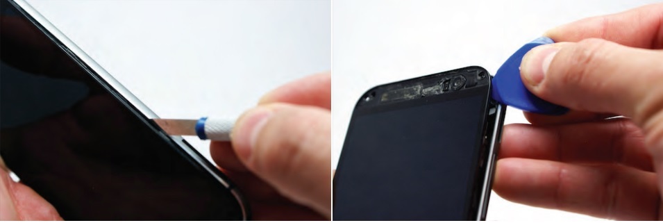
Now carefully prise off the case all round and it will detach completely
Prise up this connector
And this one
Lift up the retainer using a plastic opening tool.
And carefully pull out the tab connector.
NOW PAUSE WITHOUT MOVING ANYTHING.
NOTE THIS FLEXIBLE RIBBON
Carefully lift up the board from the left-hand side allowing it to 'hinge' on the metallic ribbon connector you have just noted and allow it to lay flat
The freed connector for the screen should have unfolded
Now the screen can be pried from the outer case, but take care as you do so not to tear the metallic ribbon between the two casings
To detach the screen it can help to use a pry tool to push the screen from behind through the slot
The screen is detached and the connector can be wiggled out through the slot
Remove the old screen and connector altogether
The connector for the new screen now has to be wiggled back through the slot
Once the connecter is pushed through the slot, you should now stick the new screen into place using suitable adhesive strip.
Fold down the ribbon connector from the screen and carefully fold the two casing halves together again, making sure that the two connectors are sticking out of the side.
Reconnect the two connectors on the right hand side by pressing down
Reinsert the ribbon connector on the left hand side and push down the retaining catch.
Clip the rear casing back on to the body

Put the bottom cover back in place and then replace all the screws.

HTC ONE X – DISASSEMBLING PROCEDURE – HOW TO REPLACE THE MOTHER BOARD

HTC One X – Disassembling procedure – How to replace the mother board

DISASSEMBLING PROCEDURE
Insert a safety pin, or other small  object in the small opening next to the Sim card slot to remove the SIM card.
The Sim Card Slot is located at the top of the rear panel.
Using a plastic opening tool, carefully separate the display screen from the rear panel.
The display assembly is a tight fit therefore the removal must be carried out carefully with firm, constant force being applied around the bottom corners and sides of the panel. Note that the top of the phone is underneath the panel, and will not come out.
If  your display is cracked, take extra caution when separating the display from the rear panel to prevent further breakage. Set aside the rear panel.
Remove the five screws at the top of the panel using a Phillips head screwdriver.
Two 2.05mm Philips head screws
Three 2.44mm Philips head screws
Also remove the screws with the warranty stickers.
Once the screws are removed, gently remove the plastic cover using a plastic opening tool to  detach the edges from the front panel.
Once you have disassembled your device, your warranty will no longer be valid
Remove the two screws at the bottom right corner of the front panel using a Phillips head  screwdriver, as shown in the image.
Two 3.35mm Philips head screws
Use tweezers to disconnect the antenna from the logic board to the PCB board.
Remove the tape connected to the motherboard.
Remove the tape holding the battery in place.
Gently lift the battery from the bottom using a plastic opening tool.
You may have to apply heat to melt the glue holding the battery in place.
Do not completely remove the battery yet
You can now disconnect the flex cable holding the PCB board place. Gently open the gates using tweezers or a plastic opening tool and use tweezers to slide the flex cable out.
Now that it's separated, remove and set aside the PCB board.
Place the battery back into its original position once the PCB board has been removed
Use tweezers to disconnect the power button flex cables.
Disconnect the volume flex cable by opening the gate and then sliding the cable out using tweezers.
Disconnect the touchscreen flex cable
Disconnect the remaining two flex cables in a similar manner before completely removing the logic board.
You may now remove the board safely

HTC MAPLE 100 - DISASSEMBLING PROCEDURE – HOW TO REPLACE THE FRONT PANEL

HTC Maple 100 - Disassembling procedure – How to replace the front panel

DISASSEMBLING PROCEDURE 
How to remove the Battery
First remove the back cover of your phone to expose the battery.
Turn the phone over and remove the battery by using your thumb to push forward on the battery and then lift it.
Take the battery out
When reassembling, make sure that the battery contacts match up.
How to remove Back Panel
Remove the four 4.9mm T6 Torx screws that secure the back panel to the rest of the phone
Remove the two 4.3mm #00 Phillips screws that secure the back panel to the rest of the phone
Use the plastic opening tool to pry the clips off
Insert the plastic opening tool along the seams at different points to it pry up
This may require a bit of force. The USB port cover may fall off in this step.
Remove the one 3.3mm #00 screw.
Use your finger or the plastic opening tool to unclip the board.
Be aware of the ribbon cable connected to the motherboard inside the phone.
Peel off the yellow piece of tape from the phone
First flip up the retaining flap with your fingernail or a plastic opening tool.
Pull on the ribbon cable gently with your fingers
Split apart the motherboard and front panel. Remove the other yellow piece of tape off of the end of the ribbon cable.
Gently pull on the ribbon cable to separate the motherboard.
Remove the four 1.9mm #00 Phillips screws.
How to remove Keyboard
Peel back the tape gently with your fingers
Remove the board gently with your fingers
Remove the keys
Using the Plastic Opening Tool, pry out the LCD screen and remove with fingers.
Be gentle because the LCD screen is fragile.
Use the Plastic Opening Tool to remove the internal ear speaker.

HTC ONE V – DISASSEMBLING PROCEDURE – HOW TO REMOVE THE CASE – HOW TO REMOVE THE BATTERY – HOW TO REPLACE VIBRATOR

HTC One V – Disassembling procedure – How to remove the case – How to remove the battery – How to replace Vibrator

HTC One V: VIBRATOR REPLACEMENT PROCEDURE
Power off your device. Remove the bottom cover by sliding it off.
Remove your SIM card. Remove the four screws securing on the bottom casing. Two 3.0 mm Philips #0 screws in the top left and right corners.
Two 2.0 mm Philips #0 screws in the bottom left and right corners.
Remove the 2.0 mm Philips #0 screw. There is an identical screw in the same spot on the other side of the phone.
Use a plastic opening tool to pry open the bottom casing. Remove the bottom casing by pulling it towards you.
Pry up rear camera panel with the plastic opening tool. Remove both screws securing on the back case.
One 4.0 mm Philips #0 screw.
One 3.0 mm Philips #0 screw.
Use jimmy tool to pry up OEM SIM Card and SD Card reader contact.
Pry from right to left to avoid potential damages to the ribbon.
Gently push on the two rear, visible corners of the bottom of the motherboard. Gently pull the screen out from the front of the phone, while feeding the OEM reader contact through the opening.
Pry up the battery with the flat end of the spudger.
Gently lift up the battery away from the edge of its housing. Use the point end of the spudger to push the connection out of its housing.
Remove the two 3.0 mm Phillips #0 screws, that are securing the camera lens.
Pry off the camera lens using a plastic opening tool.
Pry the vibrator out of the housing with a spudger. Using the tweezers, pull up on the connecting wires detaching the vibrator from the motherboard.

HTC MYTOUCH 4G – DISASSEMBLING PROCEDURE

HTC MyTouch 4G – Disassembling procedure

HTC MyTouch 4G – Disassembling procedure  – How to remove the case – How to remove the mother board – How to replace the buttons HTC MyTouch 4G

DISASSEMBLING PROCEDURE 
Flip your phone over and hold the phone with the back facing you.
Place the prying tool into the notch at the bottom of the case and pull up to remove.
Use the plastic prying tool in the upper left-hand corner notch of the battery to remove.
Remove the two T5x5mm Screws with the T5 Torx Screw driver. Remove the one Phillips screw with the Phillips #00 Screwdriver.
Use the plastic opening tools to remove the back case. There are four T5x5mm screws. Use the T5 Torx Screwdriver to remove them. Using the plastic opening tools, remove the Wifi antenna.
There are three button ribbons on the phone that need to be pulled down off of the case. With the plastic opening tools, pull the button ribbons down away from the frame without completely removing them.
After making sure the button ribbons are away from the frame, insert the plastic opening tool into the frame and remove it. Remove two Philips screws holding the Motherboard in place.
Three ribbon cables and the vibration motor need to be disconnected from the Motherboard. Using the plastic opening tools, pull up on the power button ribbon to gently detach it. Remove the vibration motor by gently pulling it off of the Motherboard.
Remove the digitizer ribbon cable with the plastic opening tools. Remove the LCD ribon cable from its connector. It is now safe to release the Motherboard from the clips holding it in place. Start at the top clip of the phone and move your way around gently releasing each clip.
Do not lift the Motherboard off the phone. The LCD Ribbon is still connected to it. Lift the Motherboard towards the left to expose the LCD clamp connector. Open the clamp connector of the LCD ribbon by carefully pulling it up with the plastic opening tools.
The Motherboard is now removed.
After removing the motherboard from the phone, the button bar is exposed and easily replaced. Use the plastic opening tools to remove the button bar and replace it with the new one.

Monday, 8 April 2019

HTC TROPHY – DISASSEMBLING PROCEDURE – HOW TO REMOVE THE CASE

HTC Trophy – Disassembling procedure – How to remove the case


HTC Trophy – Disassembling procedure – How to remove the case – How to remove the speaker – How to remove the LCD screen HTC Trophy
To disassemble the HTC Trophy, begin by removing the back cover.
Find the notch in the cover, insert the plastic opening tool, and pry up to release the clips holding the back cover down.
With the back cover removed, use the plastic opening tool to remove the battery from the HTC Trophy.
Four T5 torx screws and one small Phillips screw (#00) secure the rear portion of the case. Locate and remove these screws with the appropriate screwdrivers.
To remove the rear portion of the case, insert the plastic opening tool in the seam and work your way around the perimeter of the Trophy.
After beginning the separation at the seam, the plastic clips are easily separated with the opening tool and a slight twist of the case.
In order for the motherboard to be detached from the phone, a few connections and screws need to be removed. Begin with the connections for the display assembly. The first is a locking socket connection that secures the LCD connection in the phone. Make sure you flip up the lock to release the cable and then remove it from its socket.
The second ribbon cable is for the touch screen/ front panel. It has the same locking socket that secures the LCD connection. Make sure you flip up the lock to release the cable and then remove it from its socket.
Locate and remove the two T5 torx screws, located at the bottom of the motherboard, that secure it to the display assembly.
Locate and remove the single Phillips screw (#00). It is the last of the motherboard’s securing screws.
With all of the connections detached and the screws out of the motherboard, you can now remove the motherboard from the HTC Trophy.
The earpiece speaker is adhered to the back of the display assembly. Use the spudger to pry the speaker out of its location and remove it from the Trophy.
The rear speaker is adhered to the rear portion of the case. Use the spudger to pry the speaker out of its location and remove it from the Trophy.
To begin the process of removing the touch screen, use the heat gun/blow dryer to soften the adhesive that secures the touch screen onto the display assembly.
The touch screen needs to be separated from the display assembly. The easiest way to begin the separation is to use the torx screwdriver. From the back of the touch screen, insert the screwdriver, and push it through the front-facing camera hole.
The push from behind starts the separation of the touch screen. Use the plastic opening tool to finish the separation of the touch screen from the display assembly.
The touch screen cannot be separated completely because there is still a ribbon wire securing it to the display assembly.
The LCD screen needs to be removed next. To remove the LCD, use the heat gun/blow dyer to now soften the adhesive securing this part in place.
Using the spudger, pry the LCD screen up and out of its location in the frame. Be careful not to use too much force! If your LCD is not damaged, it can crack if you are careless during this step.
You can now remove the LCD screen and the touch screen from the HTC Trophy.

HTC HD2 – HOW TO DISASSEMBLE – HOW TO REMOVE THE CASE – HOW TO REMOVE THE BATTERY – HOW TO REPLACE THE MOTHERBOARD

HTC HD2 – How to disassemble – How to remove the case – How to remove the battery – How to replace the motherboard


Carefully pull the rear cover from the back of the phone.
Place a finger beneath the small lip on the left side of the battery.
Lay the phone down on it's screen.
Lift up on the lip and pull the battery from the phone.
Remove the four black 3.5mm T5 screws from the back of the phone.
Insert the flat end of a spudger between the frame and the display.
Slide the spudger along the seam between the frame and the display.
Using the spudger for leverage, carefully pry the frame away from the display assembly.
This process will take some effort. Continue to pry slowly and carefully until the frame begins to detach.
As it releases, pull the frame away from the phone.
The volume control tab may fall off during removal. Do not worry when it does, it can be easily reattached.
Set the phone down on its screen.
Using tweezers, unplug the small vibrator connector from its socket on the motherboard.
Pull the vibrator motor from the phone.
Disconnect the small speaker cable from its socket on the motherboard.
Remove the earpiece speaker from the phone.
Remove the five screws shown with a T5 Torx screwdriver.
Locate the flash cable in the bottom area of the phone.
Unplug the cable and pull it from the device until you reach the actual camera.
Warning: Many of the upcoming steps are difficult and may cause permanent damage to your phone.
Pull the camera flash and cover off of the board. You may need to pull the sticker that is normally behind the battery back a little.
Now locate the coaxial bluetooth cable that connects the top and bottom boards of the phone.
Use tweezers to pop both ends of the cable from the boards and remove it completely.
Now find the AP FPC, one of the smallest connectors on the bottom board.
Pop the small black tab up using tweezers, then unplug the cable.
This step is pretty much irreversible, so do not do this unless you absolutely have to.
Remember peeling back part of that big sticker in the middle? Now you get to take it all the way off.
This may take some time, and the use of the tweezers, but keep at it until the whole sticker is off.
Now find the GPS board in the upper left hand corner of the phone.
Find and pull out the white cable that connects it to the main board.
Note: The cable does not need to be unplugged from the main bottom board.
This (white) cable is connected to the underside of the bottom board, so if it gets detached, be sure to reattach before you reassemble the whole phone.
If this step does not progress easily, check to see that there are no screws still holding the board in place.
With the cable removed, pop the GPS board out of the phone using tweezers.
Using a spudger, begin to pry the copper colored board in the middle away from the phone to loosen it.
Also pry the small piece that runs under where the volume selector is on the full phone.
Caution: there is a connecter cable under the main board, so do not pull it all the way off right away.
Gently pop both the top and bottom boards off of the phone, and turn them over to the left
With the back of the main board exposed, flip up the little brown lever at the end of the connector and unplug the final cable that connects it to the main board.

HTC THUNDERBOLT – DISASSEMBLING PROCEDURE – HOW TO REMOVE THE CASE – HOW TO REPLACE THE MOTHER BOARD


HTC Thunderbolt – Disassembling procedure – How to remove the case – How to replace the mother board


Insert the plastic opening tool into the top of the Thunderbolt near the power button. Gently pry up on the rear panel around the edges until it is loose.
Lift and remove the rear panel.
Using the plastic opening tool, lift up the battery from the bottom near the kickstand. Remove the battery from the inner frame.
Use your finger to push the MicroSD card in towards the top of the phone, allowing it to be released from the casing.
Use tweezers to grab onto the MicroSD card and carefully remove it from the casing. Remove the six Phillips screws from the perimeter of the rear frame. By removing the screw with the "void" sticker on it, your Thunderbolt will no longer be covered under warranty.
Insert the plastic opening tool into the bottom of the phone underneath the soft keys. Gently pry up on the plastic cover by sliding the plastic opening tool across the bottom of the phone. Remove the plastic cover. The plastic cover will have adhesive on it making it difficult to remove.
Remove the two Phillips screws where the plastic cover was.
Insert the plastic opening tool in between the screen and the frame on the side of the phone. Slowly slide the the plastic opening tool along the side of the phone until the screen begins to separate from the frame. Do the same for the opposite side of the phone.
Carefully separate the screen and phone from the rear frame, starting from the bottom. Gently pull down on the phone and screen to fully separate it from the rear frame.
Using the tip of an plastic opening tool flip up the tab holding the capacitive button ribbon cable. Be careful opening these tabs as they are very easy to break. Use a pair of tweezers to pull the capacitive button cable out of its socket.
Lifting from the side where the ribbon was disconnected, flip over the motherboard. Remove the black tape covering the tabs connecting the motherboard and LCD.
Using the plastic opening tool pop up the two tabs connecting the LCD and motherboard.
Once the tabs have been popped up, slowly pull the two pieces away from each other. If there is resistance pulling apart the phone then a ribbon or tab has not been disconnected properly/completely.
The motherboard should now be completely disconnected

HTC DESIRE X – HOW REPLACE THE TOUCH SCREEN – HOW TO REMOVE THE CASE

HTC Desire X – How replace the touch screen – How to remove the case


Here is the Desire X, with the touch screen damaged, but working.
Once the back cover and battery are removed, its time to dissasembly. First unscrew the 5 torx #5 from back side. Then, with a flat screwdriver, push and open the back cover, from side to side.
Now, on the main board, we have to remove the screw near the camera. Release the connector on the bottom Finally, remove the antenna connector.
Once the bottom connector is loosed, you can take away the sound board and separate the flat cable from underneath. Next, the power button has to be removed. It is a bit sticky, so you may want to use a cutter or knife to separate. Long nails also work.
Now, its time to release the vibrator connector (or vibrator from holder - easier), and then release the lower connector on the main board ( see pic 2). Remove the black tape first, and then use some tweezers to pull out the connector. Once its done, lift by one side the main board, and you can see the LCD connector. Open the white tab by lifting it up at the edge, and remove the flat cable.
Now, its time to remove the product label, and keep it without bend to put back together. Then, under the silver ribbon, which is hard to remove, there is another flat connector, which must be disconnected.
The flat cable that goes to main board must be removed, and the flat cable of the touch is loosed. Remove the speaker from the top side of the phone.
To remove the glue from the LCD and touch of the screen, we have to heat all the screen, with special attention to the top and bottom zones. I have one Hot Air Station, but you can do it with a hairdryer. With more time you heat, more easy to remove, but be careful... With a Metal thin blade, insert between bezel and LCD, and bend it to start releasing.
Finally, the both parts comes apart. At the left, the LCD + touch. At the right, the chassis. Now, to assembly the unit back together, follow the steps backwards.

HTC TOUCH PRO 2 – DISASSEMBLING PROCEDURE

HTC Touch Pro 2 – Disassembling procedure


HTC Touch Pro 2 – Disassembling procedure – How to remove the battery – How to remove the display – how to remove the key board
Remove the back cover by applying pressure and sliding upward. Lift the back cover up and away from the phone.
Remove the battery by lifting upward from the slot located on the right hand side.
Using a T5 screwdriver, remove the four screws in corners as shown. Lift the top portion of the rear case.
There is a ribbon attached on the back of this part that requires caution to remove.
Using a plastic opening tool, detach the plastic casing from keyboard. This may require some force. Using a spudger or other thin tool, carefully pry up ZIF connectors as shown. This will allow the black ribbons to detach from the keyboard. Slide the two parts away from each other so that the black ribbons slide through the slots and you will now have housing into two parts.
Peel the off yellow ribbon slowly. Unscrew the fours screws in red squares (two in each square) using a 00 screwdriver. After the screws are out you will be able to easily take off the small metal pieces.
Gently peel off the yellow tape. Carefully pull the dual black strip off using force. Behind the dual black strip is very sticky piece of grey tape. Use tweezers with a grip at end to peel it off, be careful not to rip the grey tape.
Lift up the metal hinges up. Lift the keyboard frame off separating the key board from the screen.
Unscrew the two screws shown using a 00 phillips screwdriver. Wedge a flat head screwdriver or metal prying tool between the flat face and rounded edge of the phone casing. Then, slide and pry around the entire piece until the face comes off.
Use a spudger to lift up the three black latches that secure the flat electrical wire. Then, pull the wire out of the latches being careful not to rip them. Carefully, peel the silver electric tape off (force required).

HTC ONE M9 – DISASSEMBLING PROCEDURE

HTC One M9 – Disassembling procedure


Insert a SIM card eject tool or a paperclip into the small hole in the SIM card tray, located on the upper right hand side of the phone. Press to eject the tray. This may require a significant amount of force.
When reinserting the SIM card, ensure that it is in the proper orientation relative to the tray.
Insert a SIM card eject tool or a paperclip into the small hole in the SIM card tray, located on the lower right hand side of the phone. Press to eject the tray. This may require a significant amount of force.
When reinserting the SIM card, ensure that it is in the proper orientation relative to the tray.
Using a plastic opening pick or a spudger, gently pry and remove the top of the case. Remove the two 4mm T5 Torx screws on the top of the case.
Work a plastic opening pick around the perimeter of the device to separate the rear case from the display assembly. Be careful around the power and volume buttons, as they are fairly delicate.
Use a pair of tweezers to disconnect the blue and white antenna cables. Remove the two 1.5mm Phillips #00 screws securing the battery connector to the motherboard.
Use your fingers or a spudger to disconnect the ZIF connector. Use a spudger to disconnect the bottom speaker ZIF connector.
With the tweezers, carefully lift up on the tape covering the electrical strip shown in the picture.
Be careful with the tape, as it can tear easily. Use a spudger to disconnect the ZIF connector.
Disconnect the remaining three ZIF connectors. The third ZIF connector is mostly underneath the motherboard. When reassembling your device, make sure it is placed back underneath.
Remove the dual LED flash cover. Use a pair of tweezers to disconnect the two antenna cables.
Remove the three 4 mm T5 Torx screws securing the motherboard.
Use a pair of tweezers to gently lift the vibrator off of the motherboard. Use a plastic opening tool or your hands to pry the motherboard out of the case. The motherboard is secured with adhesive, so you may need to use an iOpener or heat gun to loosen the adhesive. Refer to the iOpener guide for info on this.

HTC WINDOWS PHONE 8X – DISASSEMBLING PROCEDURE

HTC Windows Phone 8X – Disassembling procedure

How to remove the battery – How to remove the power button- HTC Windows Phone 8X
HTC Windows Phone 8X: disassembling procedure 
LCD & Touch Screen Assembly
Begin the disassemble by removing the SIM card tray from the phone. Using the SIM card release tool or a paperclip, eject the tray from the phone.
To enter into the HTC Windows Phone 8X body, heat the outside perimeter of the display assembly with the heat gun/blow dryer. Use the plastic opening tool to pry the display away from the phone’s body.
Do not remove the display assembly completely because there are two ribbon cables attached to the motherboard.
The next step requires you to pry on the outside case of the phone. Maneuver the assembly to a spot where you will be able to proceed.
Look closely inside the perimeter of the phone, you will notice the plastic tabs that secure the internals to the phone's body.
Use the plastic opening tool to pry these tabs back. Allow the phones internals to pass the case backing until they can be removed from the HTC Windows Phone 8X.
You should now be able to see the internals on the case backing. With patience, very carefully separate the internals from the case backing. Now, you will begin removing the individual parts. The majority of the ribbon cables’ securing connections are FPC sockets that have a locking tab.
Flip the tab up 90 degrees and then release the first of two cables. Keep the display assembly attached while slipping the cable out of its socket.
The second ribbon cable is identical to the first. Flip the lock, release the cable, and slip it out of its socket.
Maneuver the two ribbon cables out of the small slots that allow them to pass onto the motherboard. You can now remove the display assembly from the HTC Windows Phone 8X.
Dock Port Assembly
Move your attention to the motherboard next. Start with the removal of the dock port connector and antenna plug using the spudger.
Continue with the spudger to pry the dock port assembly off of the adhesive securing it to the motherboard. You can now remove the dock port assembly from the HTC Windows Phone 8X.
Locate and remove the seven Phillips screws (#00) that hold the protective shield on the phone. The shield protects all the goodies inside. Remove the shield from the HTC phone.
Power Button
Locate the next FPC locking socket that you can flip up. Unlock and release the ribbon cable to remove the power button from the top of the HTC Windows Phone 8X.
Volume & Camera Buttons
Use the spudger to pry the volume & camera buttons’ connections. Remove the buttons on the side of the HTC phone.
Headphone Jack
The headphone jack is next to remove. It also has the FPC locking socket you can lift up from the motherboard. Unlock and release the cable.
The headphone jack is secured with a metal clip. Use the spudger to pry this clip up to release the headphone jack. You can now remove the headphone jack from the HTC Windows Phone 8X.
Unplug the upper antenna connector with the spudger by prying up on the plug to release it from the motherboard. Locate and remove the two Phillips screws (#00) that secure the battery connection to the motherboard. Once they are removed, pry up on the connection to disconnect it from the phone.
Locate and remove the three Phillips screws (#00) that secure the motherboard onto the frame assembly.
The vibrator motor is a single plug connector. It needs to be disconnected so you can remove the vibrator from the HTC Windows Phone 8X.
With the screws removed and the connections all disconnected, remove the motherboard from the HTC Windows Phone 8X frame assembly.
Battery
The battery is secured with a small amount of adhesive. Use the spudger to pry up the battery from the frame assembly. You can now remove the battery from the HTC Windows Phone 8X.

Monday, 1 April 2019

HOW TO UPGRADE THE ROM - HTC DIAMOND - RUU (RE-FLASH UPGRADE UTILITY)

HOW TO UPGRADE THE ROM - HTC DIAMOND - RUU (Re-Flash Upgrade Utility)

HTC DIAMOND - ROM Re-flash Procedure. [ROM upgrade thru RUU (Re-flash Upgrade Utility)]
Connect device to PC
1. Setting and allow USB connections in Microsoft ActiveSync.
2. Connect your device and desktop/ or laptop via USB cable.
3. Check the pop-up message from Microsoft ActiveSync when device is synchronized with PC.
Download OS Image from SDO
4. Download OS image from SDO. http://htcscm10.htc.com.tw/SDO
5. Un-zip the file and execute RUU program.
6. Select the type of USB connection with “ActiveSync” mode in the settings of menu.
7. Hold the volume down key then press power button to trigger the boot loader mode.
8. Read the pop-up message form ROM update utility and select the “I understand…” checkbox.
9. Click “Next” to proceed.
10.  Read the pop-up message form ROM update utility to follow and perform the instructions and select the “I completed…” checkbox.
11. Click “Next” to proceed.
12. Current image version confirmation.
13. Click “Update” to proceed.
14. Double verify the ROM revision which you want to update before re-flash procedure.
15. Click “Next” to proceed.
16. Read the information from pop-up message and the OS update procedure will takes 10 minutes long.
17. Click “Next” to proceed.
18. You can see the update progress from your PC and in your device.
19. The OS upgrade is finished, click “Finish” to close the utility.
Click on the pictures to Magnify

Monday, 4 March 2019

HTC MOBILES - HTC ONE M8 – DISASSEMBLING PROCEDURE – HOW TO REMOVE THE CASE – HOW REMOVE THE BATTERY – IPADS AND IPODS REPAIR AND SERVICE

HTC Mobiles - HTC One M8 – Disassembling procedure – How to remove the case – how remove the battery – IPads and IPods repair and service

Category: Smart Phone Repair and service 

Contents of this article 

  • How to remove the case 
  • How to remove the battery 
  • How to remove earpiece and speaker


HTC One M8

DISASSEMBLING PROCEDURE 
Removing Rear Cover
There are two front grills on either side of the smartphone’s display. The grills are secured in place with a small amount of adhesive. Use a heat gun or blow dryer to soften the adhesive. This will make it easier to remove the grills from the M8.
There are two front grills on either side of the smartphone’s display. The grills are secured in place with a small amount of adhesive. Use a heat gun or blow dryer to soften the adhesive. This will make it easier to remove the grills from the M8.Now, locate and remove the two small Phillips screws (#00) that secure the display assembly to the body of the smartphone (marked with orange circles). Next, locate and remove the four torx screws (T5) on the other side of the M8 that also secure the display assembly to the body/housing of the smartphone (marked with orange circles).
Insert the precision knife between the rear cover and the M8’s display assembly to free the first of many clips that secure the LCD and touch screen assembly in place.
Once there is separation between the rear cover and display assembly, use the triangle plastic opening tool to work around the perimeter of the smartphone until the rear cover is completely removed.
Removing Motherboard
First, locate and remove the two small Phillips screws (#00) that secure the connection for the battery terminal (marked with solid orange circles).
Next, locate and remove the two coaxial cable connec tions that are also secured to the motherboard (marked with open orange circles). There are two pieces of protective tape over the top of the motherboard. Use the heat gun to help soften and peel up the tape.
Now, locate and remove the three T5 torx screws that secure the motherboard down to the center of the M8. (marked with solid orange circles).
Next, locate and remove the three coaxial cable connections. There are two near the rear-facing camera and the one by the loudspeaker (marked with open orange circles).
Six locking sockets secure the motherboard’s ribbon cables in place. Release their locks by flipping the opposite side of the ribbon cable up 90 degrees, and then gently slide the cables out their sockets (marked with orange rectangles).
You can now lift the motherboard up and out.Be careful when maneuvering it through the cables and tape so that no damage occurs.
Next, remove the remainder of tape that is protecting the ribbon cables on the smartphone. Use heat, if necessary, to make it easier to remove the tape. Do not forget about the volume rocker portion of the ribbon cable, and be careful not to damage it when removing the remaining tape (marked with orange arrow).

Use additional heat to soften the securing adhesive holding the volume button in place and then with the curved tweezers remove the volume button from the HTC One (M8).
First, locate and follow the wire coming off the back of the vibrator. Pull its small plug from the locking socket. Next, use the fine tip curved tweezers to remove the vibrator from its housing and lift it out.
The wafer connection for the front-facing camera is slightly covered by a plastic cover. Remove the cover and use the fine tip curved tweezers to release the wafer connector (marked with orange arrow).
Now, locate and remove the four small Phillips screws (#00) that secure the daughterboard to the back of the display assembly. Next, release the ribbon cables in the two locking sockets that are located on either side of the daughter board (marked with orange rectangles).
You can now carefully remove the board from the M8. There are two wafer connections on the bottom of the board that might need additional maneuvering to completely remove the board.
Removing Front-Facing Camera
Use the fine tip curved tweezers to lift the front facing camera from its housing and remove it.
Removing Rear-Facing Camera
Locate and remove the single small Phillips screw (#00) that secures the rear-facing camera in place (marked with an orange circle). Now use the fine tip curved tweezers to lift the rear-facing camera from its housing and remove it .
Removing Earpiece and Loudspeaker
The earpiece speaker is held in place with adhesive. Use a small amount of heat to soften the adhesive, if necessary. Then use the fine tip curved tweezers to lift the earpiece speaker from its housing and remove it. The loudspeaker is also held in place with adhesive. Use a small amount of heat to soften the adhesive, if necessary. Then use the fine tip curved tweezers to lift the loudspeaker up,
Removing Battery
The battery is held in place with two strips of heavy-duty adhesive. To avoid damage to the battery, use the heat gun or blow dryer to soften the adhesive before trying to remove the battery.
Use the nylon spudger to gently pry the battery up,