REPAIRING AND NOT THROWING AWAY

Richtige Fernseher haben Röhren!

Richtige Fernseher haben Röhren!

In Brief: On this site you will find pictures and technical information about Service Modes, Circuit Diagrams, Firmware Update procedure, Disassemble procedure, Universal remote control set-up codes, Troubleshooting and more....

If you go into the profession, you will obtain or have access to a variety of tech tips databases HERE IT IS Master Electronics Repair !.

These are an excellent investment where the saying: 'time-is-money' rules. However, to learn, you need to develop a general troubleshooting approach - a logical, methodical, method of narrowing down the problem. A tech tip database might suggest: 'Replace C536' for a particular symptom. This is good advice for a specific problem on one model. However, what you really want to understand is why C536 was the cause and how to pinpoint the culprit in general even if you don't have a service manual or schematic and your tech tip database doesn't have an entry for your sick TV or VCR.

While schematics are nice, you won't always have them or be able to justify the purchase for a one-of repair. Therefore, in many cases, some reverse engineering will be necessary. The time will be well spent since even if you don't see another instance of the same model in your entire lifetime, you will have learned something in the process that can be applied to other equipment problems.
As always, when you get stuck, checking out a tech-tips database may quickly identify your problem and solution.In that case, you can greatly simplify your troubleshooting or at least confirm a diagnosis before ordering parts.

Happy repairing!
Today, the West is headed for the abyss. For the ultimate fate of our disposable society is for that society itself to be disposed of. And this will happen sooner, rather than later.

How to use the site:

- If you landed here via any Search Engine, you will get what you searched for and you can search more using the search this blog feature provided by Google. You can visit more posts scrolling the left blog archive of all posts of the month/year,
or you can click on the main photo-page to start from the main page. Doing so it starts from the most recent post to the older post simple clicking on the Older Post button on the bottom of each page after reading , post after post.

You can even visit all posts, time to time, when reaching the bottom end of each page and click on the Older Post button.

- If you arrived here at the main page via bookmark you can visit all the site scrolling the left blog archive of all posts of the month/year pointing were you want , or more simple You can even visit all blog posts, from newer to older, clicking at the end of each bottom page on the Older Post button.
So you can see all the blog/site content surfing all pages in it.

- The search this blog feature provided by Google is a real search engine. If you're pointing particular things it will search IT for you; or you can place a brand name in the search query at your choice and visit all results page by page. It's useful since the content of the site is very large.

Note that if you don't find what you searched for, try it after a period of time; the site is a never ending job !

..............The bitterness of poor quality is remembered long after the sweetness of todays funny gadgets low price has faded from memory........ . . . . . .....
Don't forget the past, the end of the world is upon us! Pretty soon it will all turn to dust!

©2010, 2011, 2012, 2013, 2014 Frank Sharp - You do not have permission to copy photos and words from this blog, and any content may be never used it for auctions or commercial purposes, however feel free to post anything you see here with a courtesy link back, btw a link to the original post here , is mandatory.
All posts are presented here for informative, historical and educative purposes as applicable within fair use. NOTHING HERE IS FOR SALE !

Showing posts with label MEDICAL. Show all posts

Friday, 29 March 2019

LITTMANN STETHOSCOPE HOW TO REMOVE AND ASSEMBLE THE DIAGRAM

LITTMANN STETHOSCOPE How to remove and assemble the Diagram

 How to remove and assemble the Diagram _ LITTMANN STETHOSCOPE
 
 
The stethoscope is most often used to listen to heart sounds and breathing. There are two basic types of stethoscopes for respiration system diagnostics of the human body. 
Acoustic Stethoscope
Acoustic stethoscopes are familiar to most people. Acoustic stethoscopes maintain their popularity and trust among doctors due to their longstanding use in the medical profession. Although it is taking digital stethoscopes time to catch up, they are rapidly gaining in popularity. However, acoustic stethoscopes are the most commonly used.
Electronic Stethoscope
Electronic stethoscopes function in a similar way as acoustic stethoscopes, but the sound is converted to electrical signals which can then be amplified and processed for optimal listening. Because the sounds are transmitted electronically, an electronic stethoscope can be a wireless device, can be a recording device, and can provide noise reduction, signal enhancement, and both visual and audio output.
ADVANTAGES & DISADVANTAGES
> In Digital stethoscope Amplifiers are used which amplifies the low level signal.
> Data can be stored for further analysis and consultation.
> Heart signal is displayed on the LCD screen.
> In digital stethoscope battery replacement can be tedious.
> They are expensive.
> They suffer from interference when other electronic instruments like cell phones are around.
PRINCIPLE OF OPERATION
The stethoscope is composed of three major parts. The first part is the chest piece, tubes and headset. It consists of a shallow, bell-shaped piece and a clear, stiff diaphragm, which is connected to the metal earpieces by a flexible tube. The bell is used to pick up lower frequency sounds, and the diaphragm is used for higher frequency sounds. When the chest piece is placed on the skin, vibrations within in the body are amplified by either the bell or diaphragm. These acoustic pressure waves then travel up through the tubing to the earpieces and into the listener’s ears. Digital stethoscopes offer new opportunities for computerized analysis of heart sounds. In cardiac auscultation, an examiner uses a stethoscope to listen to these sounds, which provide important information about the body condition. When the heart sounds are displayed graphically, the methodology is known as phonocardiography. As heart sounds are non-stationary signals, it is important to study both their temporal and frequency contents. Recently, with the rapid development of computer hardware and digital signal processing, heart sounds could be recorded and analyzed easily. The majority of these researchers mainly emphasize on the characteristic extraction by frequency-analysis method. Others concern on how to extract the heart rate from a weeping infant through the heart sound signals, and improve signal-to-noise ratio by adaptive filtering way.
Removing the Diaphragm and Cleaning the Chest-piece.
With the diaphragm side up, grasp the rim with the thumbs and index fingers of both hands and roll the rim off the edge of the chest-piece.
Remove the diaphragm from the rim and clean the parts in soapy water or wipe with alcohol. Chest-piece surfaces can be wiped with alcohol or soapy water.
Dry all parts and surfaces thoroughly before reassembly.
Assembly and Replacement of the Tunable Diaphragm
Using your fingertip, apply a small amount of talcum powder to the inside surface of the flexible edge of the diaphragm.
This will facilitate assembly and maintain smooth and quiet low/high frequency alternation.
Snap the diaphragm with your fingers to remove excess talc.
Insert the flexible edge of the diaphragm into the groove of the rim. This is best accomplished by starting with the rim positioned above the legible side of the diaphragm.
Visually examine the ring to ensure that the flexible edge is smoothly engaged inside the rim. If necessary, flex the assembly by pinching the outer rim edge. between the thumb and fingers.
Repeat this flexing procedure after rotating the assembly one quarter.
To attach the rim/diaphragm assembly to the chest-piece, engage the groove of the rim (with the diaphragm attached) around the chest-piece at one point and hold it in place with your thumbs.
Slowly roll the rim around and over the chest-piece edge using both thumbs, moving in opposite directions around the chest-piece.
Visually inspect the edge where the diaphragm engages the rim for uniform containment.
Minor adjustments may be made by slightly pulling and rolling the rim away from the diaphragm, allowing the diaphragm to slip into position.
Avoid extreme heat, cold, solvents, and oils.
Do not immerse your stethoscope in any liquid or subject it to steam sterilization. If disinfection is required, the stethoscope may be wiped with a 70% isopropyl alcohol solution. Wipe and clean with alcohol or soap water.

Saturday, 16 March 2019

NIDEK MARK-5 - NUVO M5C5 OXYGEN CONCENTRATOR - TROUBLESHOOTING - MEDICAL EQUIPMENT

NIDEK MARK-5 - NUVO M5C5 OXYGEN CONCENTRATOR - TROUBLESHOOTING - Medical Equipment


TROUBLESHOOTING
Capacitor Replacement.
   The capacitor helps the compressor to start and run more efficiently. If the compressor cannot start, the capacitor may be defective and require replacement.  The capacitor should be replaced at each compressor service / module replacement. To replace the capacitor, take the following steps:
  • Set the unit’s I/0 (ON/OFF) switch to the 0 (OFF) position, and unplug the power cord.
  • Remove the rear and front cabinets.
  • Disconnect the two leads to the capacitor and remove the nut from the mounting screw.
  • Remove the nut and washer below the capacitor.
  • To install the new capacitor, connect the leads and replace the capacitor and associated hardware.
Process Control Valve
   The Mark5 Nuvo uses a gear motor powered rotary cam-operated puppet valve assembly to control the air separation process. There is a feed port that connects to the air tank and an exhaust port that connects to the exhaust muffler. There are three possible valve states as follows:
  • Air feed connected to sieve bed A and exhaust connected to sieve bed B.
  • Air feed connected to sieve bed B and exhaust connected to sieve bed A.
  • Both ports closed; this is a very short time period during which air pressure builds in the air tank.  The control valve of the Mark5 Nuvo unit requires no scheduled maintenance. If a valve does not function as required, it is best to replace the complete sieve module as it is probable that one or both of the beds has been damaged.
SIEVE BED REMOVAL
   Do not expose molecular sieve (contents of bed) to air for an extended period of time. Prolonged exposure of molecular sieve to the moisture in room air results in contamination and permanent damage to the sieve material. Keep all openings to the sieve beds sealed during periods of storage.
   If replacement is necessary, you must replace both sieve beds at the same time. It is recommended to replace the sieve beds and control valve module as a complete assembly.
  • Set the unit’s I/0 (ON/OFF) switch to the 0 (OFF) position and unplug the power cord.
  • Remove the cabinet back.
  • Disconnect the 1/4-inch product tube from the top of one of the beds.
  • Remove the 4 tie-wraps ( 2 from each sieve bed ). Note their position and orientation.
  • Remove two “Z” brackets; one from the top of each of the sieve beds.
  • Lift the module up and out of the base plate cradle.
  • Unplug the valve gear motor electrical leads at the in-line connections.
  • Manipulate the module so that the black exhaust hose can be removed from the fitting on the valve.
  • Loosen the hose clamp and remove the black feed hose from the fitting on the valve.
Sieve Bed Installation
  To install the sieve beds, follow the sieve bed removal procedure in reverse order. It is very important to tighten all tubes to eliminate leaks. However, do not over tighten.
To check for leaks, take the following steps:
  • Plug in the unit.
  • Set the unit’s I/0 (ON/OFF) switch to I (ON) for three minutes with the flow meter closed to pressurize the system.
  • Apply soapy water around the hose connections at the valve and the air tank; check for leaks.
Caution: There is an electrical shock hazard with the Power ON. Be careful that no water contacts any of the electrical connections.
NOTE:  Even small leaks can affect concentrator performance and can cause contamination of the sieve. Careful leak testing is important.
TROUBLESHOOTING
Air Pressure Test (P1)
   Testing the operating pressure is a useful diagnostic tool when a concentrator has low purity and requires servicing. Units functioning normally do not require operating tests.  Use the following procedure to test the operating pressure of the unit.
  • Set the I/0 (ON/OFF) switch to the 0 (OFF) position, and unplug the power cord.
  • Remove the cabinet rear.
  • Remove the test port plug at the top of the air tank.
  • Connect the pressure test gauge to the test port.
  • Plug in the power cord, and set the I/0 (ON/OFF) power switch to the ON position. Set the flow meter to 5 l/min, and allow the unit to run at least five minutes.
  • Observe the maximum and minimum readings on the pressure test gauge.
  • The maximum reading should not exceed 34 psig (235 kPa). The minimum reading should not be less than 16 psig (110 kPa).
When you turn the unit on, it will take several minutes to reach normal operating pressures.
Higher than normal operating pressure may indicate any of the following:
    A restrictive exhaust muffler, which does not allow the waste  (purge) gas to exit the system freely.  Operate the unit with the exhaust muffler disconnected to see if the operating pressure returns to normal.
    An improperly operating control valve, confirm that the control valve is turning at 4 rpm. Time the exhaust pulse at 7.5 seconds.
Contaminated sieve beds. Change the sieve beds.
Lower than normal operating pressure may indicate any of the following:
  A  restriction  in  the  suction  resonator  or  inlet  air  filter,  which  limits  the amount of room air available to the compressor. Disconnect the suction tube at the compressor, and allow the unit to operate without the suction resonator to see if normal operating pressure returns.
  An improperly operating control valve. Confirm that the control valve does not have a leak.
  A  leak  in  the  unit,  which  allows  system  pressure  to  escape.  Leak  test  the unit.
  A compressor with reduced output.  Ensure that the concentration level at the desired liter flow is within specifications
Product Pressure Test (P2)
   Testing the product pressure is a useful diagnostic tool when a concentrator has low purity and requires servicing. Units functioning normally do not require operating tests.  Use the following procedure to test the product pressure of the unit.
  • Set the I/0 (ON/OFF) switch to the 0 (OFF) position, and unplug the power cord.
  • Remove the cabinet rear.
  • Remove the test port plug from the tee at the top of the sieve bed.
Note: The standard unit without OCSI does not have a test port; use the pressure sensor tube as the test connection.
  • Connect the pressure test gauge to the P2 test port.
  • Plug in the power cord, and set the I/0 (ON/OFF) power switch to the ON position. Set the flow meter to 5 l/min, and allow the unit to run at least five minutes.
  • Observe the maximum and minimum readings on the pressure test gauge.  The maximum reading should not exceed 16 psig (110 kPa). The minimum reading should not be less than 9 psig (62 kPa).
Low Product Pressure
Lower than normal operating pressure may indicate any of the following:
►  An  inlet  air  filter  that  limits  the  amount  of  room  air  available  to  the compressor. Disconnect the suction tube at the compressor, and allow the unit to operate without the suction resonator to see if normal operating pressure returns.
►  An improperly operating control valve. Confirm that the control valve does not have a leak.
►  A  leak  in  the  unit,  which  allows  system  pressure  to  escape.  Leak test the unit.
►  A compressor with reduced output.  Ensure that the concentration level at the desired liter flow is within specifications.
High Product Pressure
Higher than normal operating pressure may indicate any of the following:
    A restrictive exhaust muffler, which does not allow the waste  (purge) gas to exit the system freely.
Operate the unit with the exhaust muffler disconnected to see if the operating pressure returns to normal.
Check exhaust muffler and hoses for any restrictions.
An improperly operating control valve, confirm that the control valve is turning at 4 rpm. Time the exhaust pulse at 7.5 seconds.
Contaminated sieve beds. Change the sieve beds.

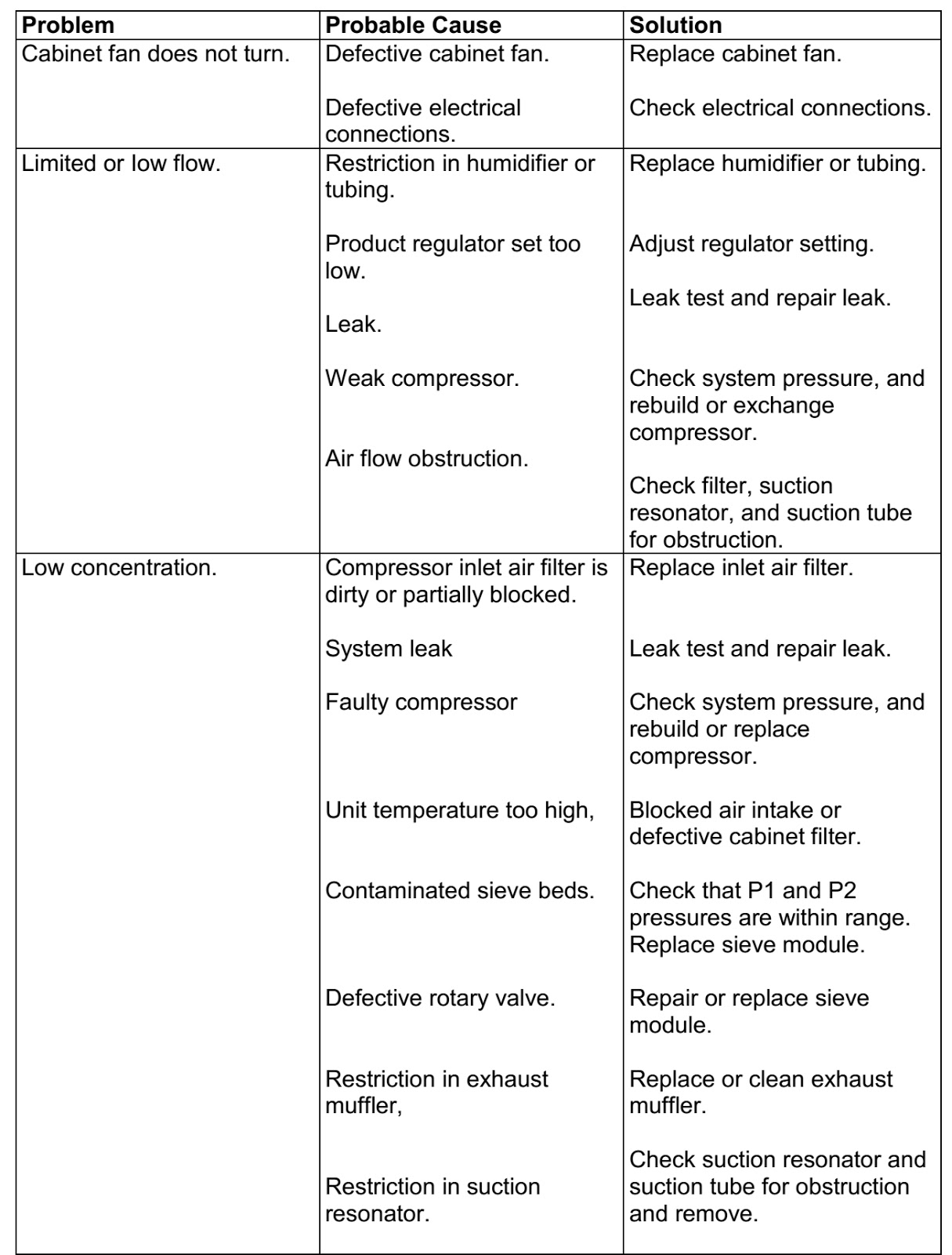
NIDEK MARK-5 NUVO M5C5 – OXYGEN CONCENTRATOR GENERAL TROUBLESHOOTING - (MEDICAL EQUIPMENT)

General Troubleshooting - NIDEK MARK-5 NUVO M5C5 – Oxygen Concentrator (Medical Equipment)

TROUBLESHOOTING
Before reviewing the troubleshooting chart, the following steps may be useful to isolate any malfunctions:
Turn the concentrator on. If unit does not turn on, refer to troubleshooting chart.
  • Make sure all filters are clean.
  • Turn flow meter completely open, up to the highest setting. The ball should rest at the top of the scale. If setting is not greater than 5.5 l/min, adjust regulator so that the ball level exceeds 5.5 l/min with the flow meter completely open.
  • Connect test pressure gauge to the outlet fitting of the unit. The pressure should read approximately 7 psig (50 kPa).
  • Connect test pressure gauge to the P1 test port on the air tank. The pressure should be cycling between approximately 16 and 34 psig (110 and 235 kPa).
  • Make sure the unit is cycling properly by observing the pressure gauge cycle between a high and a low pressure. If the unit is not cycling properly, refer to troubleshooting chart.
  • Make sure that the unit is leak free by testing all tubing connections and fittings with leak testing solution. Protect circuit board from solution and start leak test at the heat exchanger, following the air flow through the unit to the oxygen outlet. Repair all leaks by tightening connections and fittings.
  • Set the concentrator at 5 l/min and connect pressure test gauge to P2 at the top of the sieve beds. Determine pressure parameters by observing high and low pressure points on the gauge. It should cycle between approximately 9 psig and 16 psig (62 to 110 kPa). If pressures are high or low, refer to the troubleshooting chart.


Review troubleshooting chart to isolate and repair any other malfunctions.  The following diagnostic flow chart will help to isolate potential problems.
Click on pictures to Zoom. Click ß at the top left of the browser, to come back.
Tool Kit and Pressure Test Gauge
The tools needed for you to properly service the Mark5 Nuvo unit are listed below:
Requires no special tools; generally available tools including common pliers, channel lock, wire cutters, needle-nose pliers, slotted-head screwdriver, long Phillips head screwdriver, 8-inch adjustable wrench, 7/16-inch socket, 7/16-inch combination wrench, 5/8-inch combination wrench and 3/8-inch combination wrench.
For convenience, it is desirable to have a battery operated drill motor available to remove and install screws.
An accurate pressure test gauge to take both high and low pressure readings on the Mark5 Nuvo unit should be kept available at all times. This gauge connects to the pressure test ports on top of the air tank and on top of the sieve bed.

NIDEX MARK-5 NUVO M5C5 OXYGEN CONCENTRATOR DISASSEMBLE PROCEDURE

NIDEX MARK-5 NUVO M5C5 Oxygen Concentrator

Disassemble Procedure - 

DISASSEMBLY
Base Assembly
Click on the pictures to Zoom.  
Main Structure Assembly - Front View
Main Structure Assembly - Rear View
Regulator Assembly
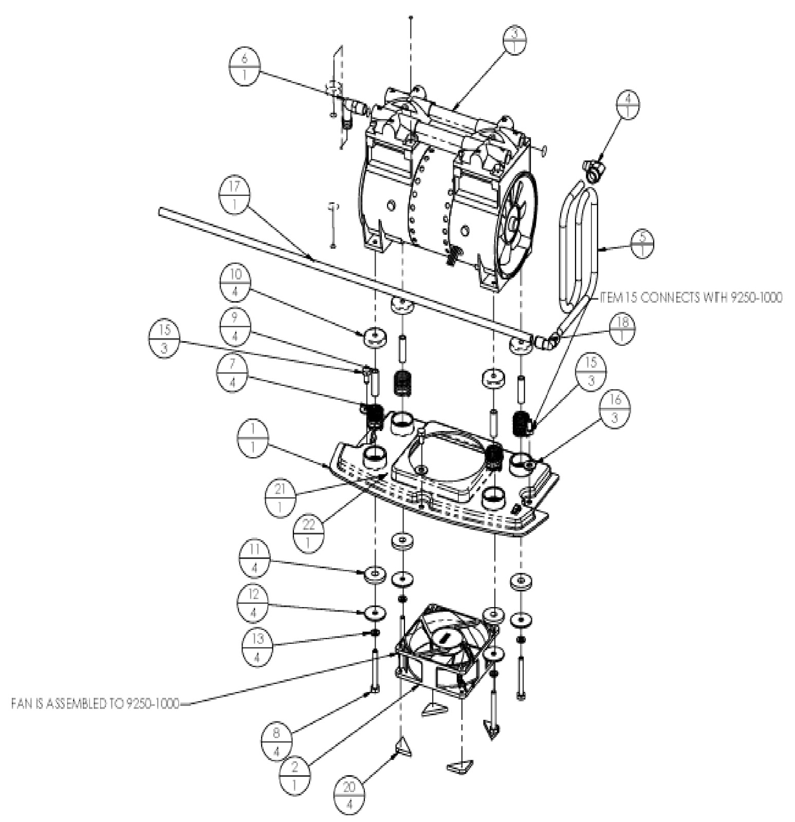
Compressor Assembly
Control Panel Assembly Unit - With OCSI - Front View
  

NIDEK NUVO M5C5 - DISASSEMBLY PROCEDURE -


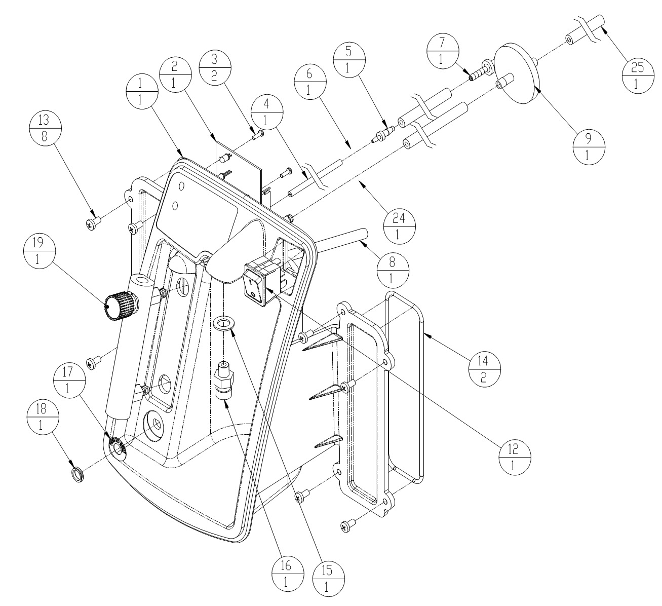
Control Panel Assembly Unit - without OCSI - Front View
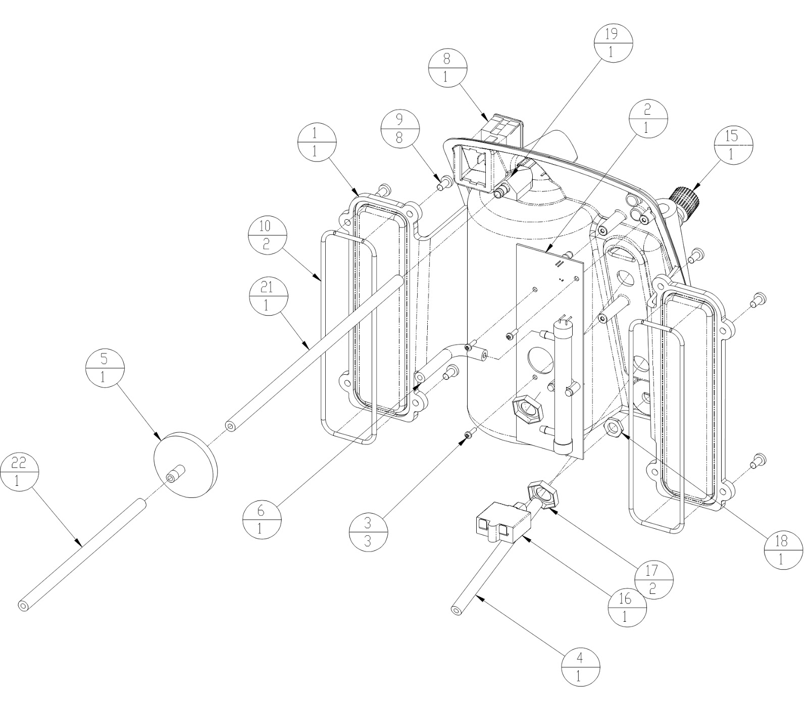
Control Panel Assembly Unit - with OCSI - Rear View
Click on the pictures to Zoom.  
Control panel assembly - standard unit - without OCSI - Front View
Rear View
Air Tank Assembly
Front Cabinet Assembly

MARK-5 NUVO-NIDEK M5C5 – Oxygen Concentrator - Disassembly Procedure - Medical Equipment


Rear cabinet assembly


Click on the pictures to Zoom. 

SIEVE module assembly


Removing Cabinet Back

To remove the cabinet back, remove two screws near the base (one on each side) and two inset screws at the top just under the handle.

Removing Cabinet Front

To remove the cabinet front, remove two screws near the base (one on each side) adjacent to the rear cabinet screws and two inset screws at the top just under the handle. It is necessary to remove the cabinet back to access the top screws.

Removing Control Panel

Eight screws hold the control panel in place; the front cover must be removed to access these screws. It is necessary to remove the electrical wiring and pneumatic tubing to fully release the control panel.

Main Structure

The weight and forces of the internal components rest solely on four parts: the main structure, the compressor plate, the base-plate and the base. These parts were specially designed and formed. They should never require replacement under normal use.

Caster Replacement

The casters are a push in type that does not require any fastener. Lay the device on its back to access the casters from the bottom. Pull them straight out away from the bottom.

Compressor

The compressor is the pump within the oxygen concentrator that supplies air to the separation process performed by the sieve beds. The pressure generated by the compressor forces oxygen to flow out of the top of the sieve columns.  The compressor is the likely cause of two potential specific problems:


  • An insufficient amount of air is supplied to the process, and
  • An excessive sound level.
Air Supply

Compressor output refers to how much compressed air the compressor can produce. This depends upon the model of the compressor, length of stroke, piston diameter, speed of rotation and condition of seals. The cup seals form the seal between the piston and the cylinder wall. As the cup seals wear, the output begins to gradually decrease. This reduction in compressor output results in less air, and thus less oxygen, entering the sieve beds. Therefore, the production of oxygen decreases.  Because this drop in oxygen production occurs over a long period of time, preventive maintenance on the compressor is not required.

Sound Level
The sound level is largely determined by the condition of the compressor’s bearings.  There are four bearings located within the compressor that allow the inner components of the compressor to rotate. If the bearings wear to the point that they become loose and noisy, the compressor becomes noticeably loud and needs servicing. Primarily its operating temperature determines the life of a compressor. It is extremely important that the cabinet air filters are cleaned and replaced as required.

NIDEK NUVO-8 - OXYGEN CONCENTRATOR - TROUBLESHOOTING - LOW PRODUCT PRESSURE - HIGH PRODUCT PRESSURE - GENERAL TROUBLESHOOTING.

Oxygen Concentrator - NIDEK NUVO-8 - TROUBLESHOOTING - Low product pressure - High product pressure - General troubleshooting.

TROUBLESHOOTING
Air Pressure Test (P1)
Testing the operating pressure is a useful diagnostic tool when a concentrator has low purity and requires servicing. Units functioning normally do not require operating tests.
  • Set the I/0 (ON/OFF) switch to the 0 (OFF) position, and unplug the power cord.
  • Remove the cabinet rear.
  • Remove the air supply tubing going to the control valve and install the test port T-fitting. Figures shows the normal operating configuration for the unit. and the installation of the test ports.
  • Connect the pressure test gauge to the test port.
  • Plug in the power cord, and set the I/0 (ON/OFF) power switch to the ON position. Set the flow meter to 8 l/min, and allow the unit to run at least five minutes.
  • Observe the maximum and minimum readings on the pressure test gauge.
  • The maximum reading should not exceed 40 psig (275 kPa). The minimum reading should not be less than 13 psig (90 kPa).
NOTE When you turn the unit on, it will take several minutes to reach normal operating pressures.
High Operating Air Pressure (P1)
Higher than normal operating pressure may indicate any of the following:
  • A restrictive exhaust muffler, which does not allow the waste (purge) gas to exit the system freely.
  • Contaminated sieve beds. Change the sieve beds.
Low Operating Air Pressure (P1)
Lower than normal operating pressure may indicate any of the following:
  • A restriction in the suction resonator or air intake filter, this limits the amount of room air available to the compressor. Disconnect the suction tube at the compressor, and allow the unit to operate without the suction resonator to see if normal operating pressure returns.
  • An improperly operating control valve. Confirm that the control valve does not have a leak.
  • A leak in the unit, which allows system pressure to escape. Leak test the unit.
  • A compressor with reduced output.  Ensure that the concentration level at the desired liter flow is within specifications listed.
Product Pressure Test (P2)
Testing the product pressure is a useful diagnostic tool when a concentrator has low purity and requires servicing. Units functioning normally do not require operating tests.  Use the following procedure to test the product pressure of the unit.
  • Set the I/0 (ON/OFF) switch to the 0 (OFF) position, and unplug the power cord.
  • Remove the cabinet rear.
  • Remove the plug from the T-fitting atop the valve and install the test port tubing (1/4” OD tubing is required). Figure 1 above  shows the normal operating configuration for each unit. Figure 2 shows the installation of the test port tubing.
  • Connect a pressure test gauge to the P2 test port tubing.
  • Plug in the power cord, and set the I/0 (ON/OFF) power switch to the ON position. Set the flow meter to 8 l/min, and allow the unit to run at least five minutes.
  • Observe the maximum and minimum readings on the pressure test gauge.  The maximum reading should not exceed 40 psig (275kPa). The minimum reading should not be less than 13 psig (90 kPa).
Low Product Pressure (P2)
Lower than normal operating pressure may indicate any of the following:
  • An inlet air filter that limits the amount of room air available to the compressor. Disconnect the suction tube at the compressor, and allow the unit to operate without the suction resonator to see if normal operating pressure returns.
  • An improperly operating control valve. Confirm that the control valve does not have a leak.
  • A leak in the unit, which allows system pressure to escape. Leak test the unit.
  • A compressor with reduced output. Ensure that the concentration level at the desired liter flow is within specifications listed.
High Product Pressure (P2)
Higher than normal operating pressure may indicate any of the following:
  • A restrictive exhaust muffler, which does not allow the waste (purge) gas to exit the system freely.
  • Check exhaust muffler for any restrictions
  • Contaminated sieve beds. Change the sieve beds.
GENERAL TROUBLESHOOTING
Before reviewing the troubleshooting chart, the following steps may be useful to isolate any malfunctions:
  • Turn the concentrator on. If unit does not turn on, refer to troubleshooting chart.
  • Make sure all filters are clean.
  • Turn flow meter completely open, up to the highest setting. The ball should rest at the top of the scale. If setting is not greater than 8.5 l/min, adjust regulator so that the ball level exceeds 8.5 l/min with the flow meter completely open.
  • Connect test pressure gauge to the outlet fitting of the unit. The pressure should read approximately 17 psig (117 kPa).
  • Connect test pressure gauge to the P1 test port on the valve inlet. The pressure should be cycling between approximately 13 and 40 psig (90 and 275 kPa).
  • Make sure the unit is cycling properly by observing the pressure gauge cycle between a high and a low pressure. If the unit is not cycling properly, refer to troubleshooting chart.
  • Make sure that the unit is leak free by testing all tubing connections and fittings with leak testing solution. Protect circuit board from solution and start leak test at the compressor outlet, following the air flow through the unit to the oxygen outlet. Repair all leaks by tightening connections and fittings.
  • Set the concentrator at 8 l/min and connect pressure test gauge to P2 at the top of the sieve module. Determine pressure parameters by observing high and low pressure points on the gauge. It should cycle between approximately 13 psig and 40 psig (90 to 275 kPa). If pressures are high or low, refer to the troubleshooting chart.
  • Review troubleshooting chart to isolate and repair any other malfunctions.
The following diagnostic flow chart will help to isolate potential problems.

Click on the chart to Zoom.