REPAIRING AND NOT THROWING AWAY

Richtige Fernseher haben Röhren!

Richtige Fernseher haben Röhren!

In Brief: On this site you will find pictures and technical information about Service Modes, Circuit Diagrams, Firmware Update procedure, Disassemble procedure, Universal remote control set-up codes, Troubleshooting and more....

If you go into the profession, you will obtain or have access to a variety of tech tips databases HERE IT IS Master Electronics Repair !.

These are an excellent investment where the saying: 'time-is-money' rules. However, to learn, you need to develop a general troubleshooting approach - a logical, methodical, method of narrowing down the problem. A tech tip database might suggest: 'Replace C536' for a particular symptom. This is good advice for a specific problem on one model. However, what you really want to understand is why C536 was the cause and how to pinpoint the culprit in general even if you don't have a service manual or schematic and your tech tip database doesn't have an entry for your sick TV or VCR.

While schematics are nice, you won't always have them or be able to justify the purchase for a one-of repair. Therefore, in many cases, some reverse engineering will be necessary. The time will be well spent since even if you don't see another instance of the same model in your entire lifetime, you will have learned something in the process that can be applied to other equipment problems.
As always, when you get stuck, checking out a tech-tips database may quickly identify your problem and solution.In that case, you can greatly simplify your troubleshooting or at least confirm a diagnosis before ordering parts.

Happy repairing!
Today, the West is headed for the abyss. For the ultimate fate of our disposable society is for that society itself to be disposed of. And this will happen sooner, rather than later.

How to use the site:

- If you landed here via any Search Engine, you will get what you searched for and you can search more using the search this blog feature provided by Google. You can visit more posts scrolling the left blog archive of all posts of the month/year,
or you can click on the main photo-page to start from the main page. Doing so it starts from the most recent post to the older post simple clicking on the Older Post button on the bottom of each page after reading , post after post.

You can even visit all posts, time to time, when reaching the bottom end of each page and click on the Older Post button.

- If you arrived here at the main page via bookmark you can visit all the site scrolling the left blog archive of all posts of the month/year pointing were you want , or more simple You can even visit all blog posts, from newer to older, clicking at the end of each bottom page on the Older Post button.
So you can see all the blog/site content surfing all pages in it.

- The search this blog feature provided by Google is a real search engine. If you're pointing particular things it will search IT for you; or you can place a brand name in the search query at your choice and visit all results page by page. It's useful since the content of the site is very large.

Note that if you don't find what you searched for, try it after a period of time; the site is a never ending job !

..............The bitterness of poor quality is remembered long after the sweetness of todays funny gadgets low price has faded from memory........ . . . . . .....
Don't forget the past, the end of the world is upon us! Pretty soon it will all turn to dust!

©2010, 2011, 2012, 2013, 2014 Frank Sharp - You do not have permission to copy photos and words from this blog, and any content may be never used it for auctions or commercial purposes, however feel free to post anything you see here with a courtesy link back, btw a link to the original post here , is mandatory.
All posts are presented here for informative, historical and educative purposes as applicable within fair use. NOTHING HERE IS FOR SALE !

Showing posts with label SCHEMATIC DIAGRAM. Show all posts

Wednesday, 30 December 2020

PANASONIC TC-L32E5 HOW TO ENTER THE SERVICE MODE, LED BLINKING CODES, POWER BOARD ELECTRIC SCHEMATIC DIAGRAM


Chassis: LA35  Destination: USA.  AC 110-127 V, 60 Hz

1. Do not press panel surface to avoid blue spot on the panel display.

2. Do not use hard cloth or rub the surface too hard. This may cause scratches on the surface.

3. Take care not to subject the TV’s surface to water or detergent. Any liquid (including pets urine) if enters the product could lead to TV failure.

4. Take care not to subject the surface to insect repellent, solvent, thiner or other voiltile substances. This may degrade surface quality or cause peeling of the paint.

5. The surface of the display panel is specially treated and may be easily damaged. Take care not to tap or scratch with your fingernail or other hard objects.

Service Mode:  How to enter into Service Mode

While pressing [VOLUME ( - )] button of the main unit, press [INFO] button of the remote control three times within 2 seconds.


Contents of adjustment mode

 Value is shown as a hexadecimal number.

 Preset value differs depending on models.

 After entering the adjustment mode, take note of the value in each item before starting adjustment.


How to exit

Switch off the power with the [POWER] button on the main unit or the [POWER] button on the remote control.

SRV-TOOL:  How to access

1. Select [SRV-TOOL] in Service Mode.

2. Press [OK] button on the remote control.


Display of SOS History

SOS History (Number of LED blinking ) indication.

From left side; Last SOS, before Last, three occurrence before, 2nd occurrence after shipment, 1st occurrence after shipment.

This indication except 2nd and 1st occurrence after shipment will be cleared by [Self-check indication and forced to factory shipment setting].

POWER ON TIME/COUNT

Note : To display TIME/COUNT menu, highlight position, then press MUTE for 3sec.

Time : Cumulative power on time, indicated hour : minute by decimal

Count : Number of ON times by decimal

Note : This indication will not be cleared by either of the self-checks or any other command.

Exit

Disconnect the AC cord from wall outlet.

Self Check Mode

1. Press the ‘MENU’ button (on the remote control) and the ‘VOL DOWN’ button on the LCD panel.

2. Press ON/OFF button on the panel to Exit.

Hotel Mode Adjustment

1. Press the ‘VOLUME DOWN’ button on the TV panel and simultaneously press the INPUT button on the remote control 3 times to enter Hotel Mode.

2. Set Hotel mode ‘on/off’, then press ‘EXIT’ to come out.

Hotel Mode

1. Purpose

Restrict a function for hotels.

2. Access command to the Hotel mode setup menu.

In order to display the Hotel mode setup menu, please enter the following command (within 2 second). [TV] : Vol [Down] + [REMOTE] : INPUT (3 times).

Then, the Hotel mode setup menu is displayed.


3. To exit the Hotel mode setup menu

Disconnect AC power cord from wall outlet.

4. Explain the Hotel mode setup menu

Troubleshooting Guide

Use the self-check function to test the unit.

1. Checking the IIC bus lines

2. Power LED Blinking timing

Check of the IIC bus lines:  How to access

Self-check indication only:

Produce TV reception screen, and while pressing [VOLUME ( - )] button on the main unit, press [OK] button on the remote control for more than 3 seconds.

Self-check indication and forced to factory shipment setting:

Produce TV reception screen, and while pressing [VOLUME ( - )] button on the main unit, press [MENU] button on the remote control for more than 3 seconds.

Exit

Disconnect the AC cord from wall outlet.

Screen display

Power LED Blinking timing chart

1. Subject

Information of LED Flashing timing chart.

2. Contents

When an abnormality occurs, the protection circuit will operate and reset the unit to stand by mode. During this time, the defective block can be identified by the number of blinking times of the Power LED on the front panel of the unit as follow:

No Power

First check point

There are following 2 states of No Power indication by power LED.

1. No lit

2. Red is lit then turns red blinking a few seconds later.

Voltage chart of A-Board and P-Board

Power board PWB

P-Board Schematic Diagram [TNPA5596CP]


Thursday, 12 November 2020

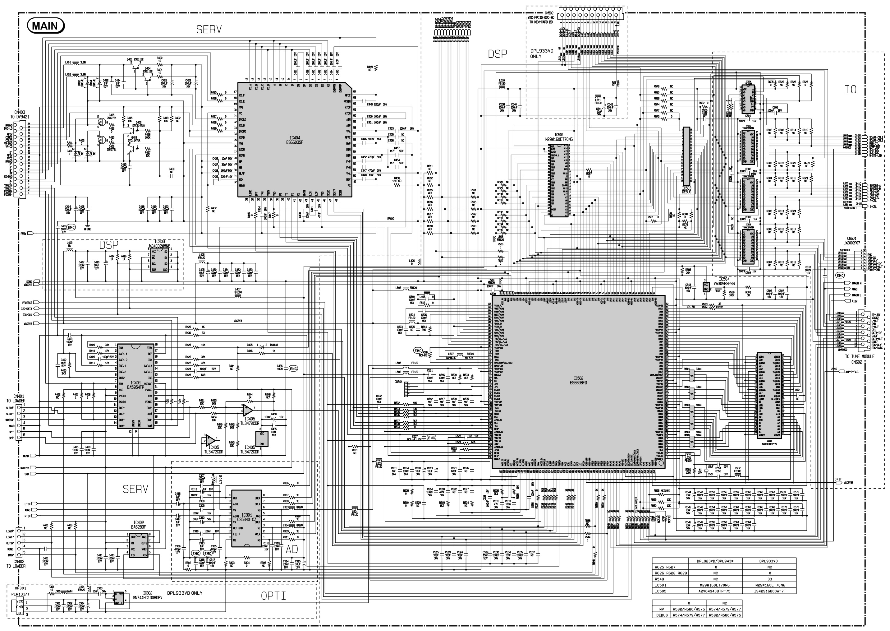
THOMSON DPL923VD, DPL933VD, DPL943W STEREO AMPLIFIER - DVD PLAYER SCHEMATIC DIAGRAM

Nominal output power:  4 x 50W:  2 x 100W

CONTROL / DISPLAY SCHEMATIC DIAGRAM

PT6315, HRM557BC5109, HT48R05


MAIN SCHEMATIC DIAGRAM: 1 OF 3

STA308A, STA515, BA4558F


MAIN SCHEMATIC: 2 OF 3

ES6603SF, BA5954FP, CS5340-C7, BA6289F, SN74AHC1GOBDBV, ES6698FD, M29W160ET70NG


MAIN SCHEMATIC: 3 0F 3

BU4052BF


MEMORY CARD READER SCHEMATIC DIAGRAM

GL816, 74VHC125M, 74LCX138M, 74LVX74MTR, CFCARD4312-23xxx


POWER SUPPLY [SMPS] SCHEMATIC DIAGRAM

L6565, VIPer53


Friday, 30 October 2020

SONY WRT 807B - UHF SYNTHESIZED WIRELESS MICROPHONE SCHEMATIC DIAGRAM, TROUBLESHOOTING, DISASSEMBLE AND REASSAMBLE PROCEDURE


LCD readout of various information
The microphones LCD shows the current channel number, frequency, input attenuation setting, and residual battery power.
The accumulated battery use time is also indicated (in oneminute increments) to allow precise monitoring of battery use.
Automatic saving of channel and input attenuation settings
All channel and input attenuation settings are automatically saved when the microphone is turned off (and are maintained even when the battery is removed), thus eliminating the need to make the same settings again the next time you use the microphone.
Highly reliable electronic attenuator
Adjustable in a range of 0 dB to 21 dB in 3-dB steps, the built-in input level attenuator reduces signal distortion during the input of excessively strong audio signals.
Tone signal-incorporated RF carrier signal
The microphone transmits an RF carrier signal that incorporates a tone signal to enable any tuner with a tone squelch circuit to pick out only the target audio signal.
Wide dynamic range and low noise
The microphones compander (compressor/expander) system enables transmission over a wide dynamic range with minimum noise.

• When operating two or more microphones, keep the microphones separated from each other by a distance of at least 30 cm (1 foot).
• Keep the microphones at least 3 meters (10 feet) away from receiving antenna.

CH (channel) indication
Displays the transmitting channel.
Each time you press the SET button in Transmit mode, the channel indication changes as follows.

Transmitting channel: The current transmitting channel setting.
Transmitting frequency: The current transmitting frequency setting.
Attenuation: The input attenuation setting in decibels.  Can be set within a range of 0 dB to 21 dB in 3-dB steps.
Accumulated battery use time: The accumulated time of battery use (in 1-minute increments).

SET button
In Transmit mode, press this button to change the indicated items in the lower half of the liquid-crystal display.
To change to Setting mode, turn the POWER switch to ON while holding this button down. Then press this button to select the items to be indicated.

Initiating Setting Mode

Enter Setting mode to change the transmitting channel, the transmitting frequency and the attenuation level, or to reset the accumulated battery use time indication.
To enter Setting mode
While holding down the SET button, turn the POWER switch to ON.
Hold the SET button down until an indication appears on the liquid-crystal display.
The microphone enters Setting mode and the indication before the microphone was previously turned OFF flashes on the liquid-crystal display.
Pressing the SET button cycles the modes in the order of Channel selection mode, Frequency selection mode, Attenuator adjustment mode and Accumulated time indication reset mode.
Note
On the model available in Europe, the transmitting channels are grouped in four sets as shown in “Sony Wireless Microphone System Frequency List.”

[On the model available in Europe, set the channel group indication (the left two digits) first. Press the + or – button to toggle the channel group (e.g., for CE62 model: 00 y 62 y 63 y 64) and press the SET button. Then, the remaining four digits start to flash for setting the channel number]

Changing the Transmitting Channel

The transmitting channel can be selected through either the channel number or the frequency.
1 Set the microphone to Setting mode.  If the channel number (or frequency) indication does not appear,
(or)
press the SET button until the channel number frequency) indication appears.

Changing the Input Attenuation Setting

The input attenuation setting can be changed within a range of 0 dB to 21 dB (in 3-dB steps) in either Setting mode or Transmit mode.

Changing the input attenuation in Setting mode
1
Set the microphone to Setting mode.
2 If the attenuation level is not displayed, press the SET button until it appears.
3 Press the + or – button to change the attenuation setting.

4 Once the desired level appears, turn the POWER switch to OFF to release Setting mode, or press the SET button to continue operations in Setting mode.

The next time you turn on the microphone (by turning the POWER switch to ON), the microphone enter Transmit mode with the selected attenuation setting

Changing the input attenuation in Transmit mode
You can also change the input attenuation setting while transmitting
If button in Transmit mode.
1 the attenuation level is not displayed, press the SET until it appears.
2 Press the + or – button to change the attenuation setting.

Resetting the Accumulated Battery Use Time Indication

The accumulated battery use time is the total time (in hours and minutes) the battery has been used. It is recorded whenever the WRT-807B is on.
Reset the indication to 00:00 whenever you replace the battery.
1 Set the microphone to Setting mode.
2 If
4 Turn the accumulated battery use time is not displayed, press the SET button until it appears.
3 Press the – button.
The indication resets to 00:00.

Press the + button while the 00:00 indication is on to go back to previous value.

Troubleshooting

Disassembly procedure


Reassembly procedure

EEPROM (IC202, DP-306 board) replacement

When replacing EEPROM (IC202) on the DP-306 board or replacing DP-306 board, perform the following operation.
When the power is turned on initially after the replacement:
1. “Error 11” is indicated on the display.
2. Turn off the power. Next turn on the power again.
Confirm that “CE57B” (for CE57 model) is indicated on the display.
Confirm that “CE62B” (for CE62 model) is indicated on the display.
Confirm that “CE67B” (for CE67 model) is indicated on the display.
Confirm that “U30B” (for U30 model) is indicated on the display.
Confirm that “U42B” (for U42 model) is indicated on the display.
Confirm that “U62B” (for U62 model) is indicated on the display.
Confirm that “U66B” (for U66 model) is indicated on the display.

How to make a AF input cable

Schematic diagram and PWB layout


PWB


Friday, 16 October 2020

TCL L55E5800 POWER BOARD (SMPS) SCHEMATIC DIAGRAM, HITACHI 15LD2550B, 15LD2550EB POWER BOARD SCHEMATIC (STR-W6253)


TCL L55E5800 POWER BOARD SCHEMATIC diagram


HITACHI 15LD2550B, HITACHI 15LD2550EB SMPS schematic diagram


HITACHI 19LD4550U – SMPS (Power board) schematic diagram


Wednesday, 30 September 2020

BOOG DPS21K5 AND ROCKFORD FOSGATE CAR AMPLIFER SCHEMATIC DIAGRAM

 BOOG DPS21K5 schematic

USED Ics: TL074, IRS2092, IRFBA90


ROCKFORD FOSGATE AUTO AMPLIFIER – 100+100 WATTS -  SCHEMATIC

USED Ics: LM833SM, BUZ11[FET], TL494SM, IRF9540, IRF540H


Tuesday, 29 September 2020

PHILIPS 39PFL5046, PHILIPS 42PFL3300 , PHILIPS 32PFL3200 LCD TVS – POWER SUPPLY SCHEMATIC DIAGRAMS


 Philips 32PFL3200 POWER SUPPLY (SMPS) Schematic diagram – 715G4831


Philips 42PFL3300 POWER SUPPLY (SMPS) Schematic diagram – 715G4922

715G3936 & 715G3967

Philips 39PFL5046 POWER SUPPLY (SMPS) Schematic diagram