REPAIRING AND NOT THROWING AWAY

Richtige Fernseher haben Röhren!

Richtige Fernseher haben Röhren!

In Brief: On this site you will find pictures and technical information about Service Modes, Circuit Diagrams, Firmware Update procedure, Disassemble procedure, Universal remote control set-up codes, Troubleshooting and more....

If you go into the profession, you will obtain or have access to a variety of tech tips databases HERE IT IS Master Electronics Repair !.

These are an excellent investment where the saying: 'time-is-money' rules. However, to learn, you need to develop a general troubleshooting approach - a logical, methodical, method of narrowing down the problem. A tech tip database might suggest: 'Replace C536' for a particular symptom. This is good advice for a specific problem on one model. However, what you really want to understand is why C536 was the cause and how to pinpoint the culprit in general even if you don't have a service manual or schematic and your tech tip database doesn't have an entry for your sick TV or VCR.

While schematics are nice, you won't always have them or be able to justify the purchase for a one-of repair. Therefore, in many cases, some reverse engineering will be necessary. The time will be well spent since even if you don't see another instance of the same model in your entire lifetime, you will have learned something in the process that can be applied to other equipment problems.
As always, when you get stuck, checking out a tech-tips database may quickly identify your problem and solution.In that case, you can greatly simplify your troubleshooting or at least confirm a diagnosis before ordering parts.

Happy repairing!
Today, the West is headed for the abyss. For the ultimate fate of our disposable society is for that society itself to be disposed of. And this will happen sooner, rather than later.

How to use the site:

- If you landed here via any Search Engine, you will get what you searched for and you can search more using the search this blog feature provided by Google. You can visit more posts scrolling the left blog archive of all posts of the month/year,
or you can click on the main photo-page to start from the main page. Doing so it starts from the most recent post to the older post simple clicking on the Older Post button on the bottom of each page after reading , post after post.

You can even visit all posts, time to time, when reaching the bottom end of each page and click on the Older Post button.

- If you arrived here at the main page via bookmark you can visit all the site scrolling the left blog archive of all posts of the month/year pointing were you want , or more simple You can even visit all blog posts, from newer to older, clicking at the end of each bottom page on the Older Post button.
So you can see all the blog/site content surfing all pages in it.

- The search this blog feature provided by Google is a real search engine. If you're pointing particular things it will search IT for you; or you can place a brand name in the search query at your choice and visit all results page by page. It's useful since the content of the site is very large.

Note that if you don't find what you searched for, try it after a period of time; the site is a never ending job !

..............The bitterness of poor quality is remembered long after the sweetness of todays funny gadgets low price has faded from memory........ . . . . . .....
Don't forget the past, the end of the world is upon us! Pretty soon it will all turn to dust!

©2010, 2011, 2012, 2013, 2014 Frank Sharp - You do not have permission to copy photos and words from this blog, and any content may be never used it for auctions or commercial purposes, however feel free to post anything you see here with a courtesy link back, btw a link to the original post here , is mandatory.
All posts are presented here for informative, historical and educative purposes as applicable within fair use. NOTHING HERE IS FOR SALE !

Showing posts with label THOMSON. Show all posts

Friday, 16 April 2021

REPAIRING / SERVICING TV THOMSON T55FSE1170

Technical description and composition of the THOMSON T55FSE1170 TV, type of panel and modules used. Module composition.
Composition/Specifications
THOMSON T55FSE1170
LCD TV LED T55FSE1170 | Year of manufacture: 2018
Screen diagonal: 54.6" (139 cm)
Aspect ratio: 16:9
Resolution: 1920x1080
Refresh rate:     50Hz
LED backlight: Yes, Direct LED
Support HD: 1080p Full HD
Brightness: 290 cd/m2
Contrast: 4000:1
Viewing Angle: 178°
Pixel Response Time:     6.5 ms
Progressive scan: Yes
Digital tuner: DVB-T, DVB-T2, DVB-C, DVB-S, DVB-S2
Number of channels: 799
Teletext: there is
Multimedia: MP3, MPEG4, HEVC (H.265), Xvid, MKV, JPEG
Sound stereo: there is
Sound power: 16W (2x8W)
Acoustics: two speakers
Interface: AV, HDMI x2, USB x2
Headphone jack: yes
TV weight: 13 kg
Dimensions: with stand 1242x770x250 mm
without stand 1242x729x80 mm
AC power consumption: 100W
Find out more...
THOMSON T55FSE1170

THOMSON LED
Model: T55FSE1170

Chassis/Version: T.MS3663S

Panel: LVF550CSDX

LED driver (backlight): integrated into PSU

PWM LED driver: OB3365RP

MOSFET LED driver: MDF13N50

Power Supply (PSU): SHG6004C-101H

PWM Power: FA1A60N, FA6B20N

MOSFET Power: MMD60R580Q

MainBoard: T.MS3663S.782 1MS663E0S2A

MainBoard IC: CPU, SPI Flash, AUDIO, DC/DC

MainBoard: CDT-9NT372-RF01 & SAT
General advice about LCD LED TV repair
Possible problems

- THOMSON T55FSE1170 TV set doesn't turn on at all. No reaction to remote control or front panel controls. No indicator light is on or is not blinking.

In such cases the SHG6004C-101H power supply is usually the defective one. It is necessary to measure its output voltages, and if there are no such voltages, check the condition of the power switches (MMD60R580Q) of the converters and the rectifier diodes for possible short circuits.
At breakdowns in the secondary circuits of the inverter, usually it can crash in the short-circuit mode, and at short circuit in the power elements of the primary circuit most often the mains fuse or current sensor in the source of the key breaks.
Breakdown of Mos-Fet switches used in pulse sources is often caused by failures of other elements, for example, in PWM controller power supply circuit, in frequency-retaining or damping circuits, as well as in the Negative Feedback Stabilization. PWM microcircuits FA1A60N, FA6B20N are usually checked by replacement with the new ones, or known to be in good condition.

- No picture, but there is sound and reaction to the remote control. Or the image may appear for a second immediately after turning on.

In some of these cases the malfunction is caused by the lack of display backlighting. The cause may sometimes be in the power supply of LEDs, but more often in their failure (breakdown or breakage), sometimes in violation of the contact connections of LED strips.
When trying to identify breaks in the LED strips, you should keep in mind that it is difficult to do without disassembling the panel. You need, for example, a current source to open the PN-junctions connected in series.

If THOMSON T55FSE1170 has no picture but sound, often the LVF550CSDX display backlight simply does not work. Moreover, in LED televisions, the LEDs inside the panel usually fail, less often the LED driver.
In such cases you can see a faintly visible image when external light hits the screen.

To replace the LEDs requires disassembly of the LCD panel LVF550CSDX - a process which requires a master of experience and skill. We do not recommend to perform such works by yourself to owners of TV sets and craftsmen who have no experience in LCD panel repair

READ HOW TO REPAIR THE TV LED BACKLIGHT --------------> HERE.

If there is no image, but the backlight works - the screen becomes slightly lighter when you turn it on, and you can see the light through the holes in the body of the panel when the TV is open.
In this case the panel may be defective - damage to the strips, cables, for example, as a consequence of moisture after an unsuccessful washing of the screen, the T-CON board (Timing Controller) may be defective. But quite often the MainBoard T.MS3663S.782 is defective, and so is the software.
Then first it is necessary to check the panel power supply voltage, the fuses on the T-CON board, as well as the supply and reference voltages of the column and line drivers - VGH, VGL, Vcom.
If these measurements are within normal limits, you need to trace with an oscilloscope the LVDS signals from MainBoard T.MS3663S.782, as well as synchronizing signals to driver stubs.

Filled or unsuccessfully washed LED TV screens can be repaired in about half of the cases, usually if there is no significant damage to the panel stubs and slats.

- Front panel LED blinks, TV set does not turn on, remote control is unresponsive.

Repair or diagnostic of the T.MS3663S.782 motherboard should begin with checking the stabilizers and power converters necessary to power the chips and matrix. If necessary, software (software) should be updated or replaced. Sometimes elements of MainBoard - CPU, SPI Flash, AUDIO, DC/DC need checking or replacement (if necessary). In cases where a BGA processor is used, its failure is usually detected by local heating method.

If you cannot tune to the terrestrial or cable TV channels, make sure the software is correct, and the supply voltages on the CDT-9NT372-RF01 & SAT tuner pins are correct. It is also necessary to control with an oscilloscope the presence of pulses of data exchange between the tuner and the processor via the I2C bus.

Remember! Attempts to repair your THOMSON T55FSE1170 TV set yourself, if you do not have the necessary skills and experience, is categorically not recommended and is fraught with negative consequences, up to the complete unrepairability of the device!

Refinement after repair of the backlight. SHG6004C-101H, OB3365RP. Information from the master.

Reduce backlight current from 410 mA to 250 mA - On the SHG6004C-101H board on pin 2 of ISET chip OB3365RP in parallel resistors R229 47 kOhm and R239 68 kOhm. Removed 68 kOhm resistor.
Driver current limitation. OB3365RP. 

General info.

To reduce the backlight current you can remove one of the resistors on pin 2 of the ISET chip OB3365RP, so that their total resistance increases in proportion to the reduced current in the LEDs.
More on MainBoard Repair

The appearance of the MainBoard T.MS3663S.782 is shown in the figure below:


T.MS3663S.782

MainBoard Appearance

SHG6004C-101H:

SHG6004C-101H

Main features of THOMSON T55FSE1170:

LVF550CSDX matrix (LED panel) is installed.
To power the LED backlight used converter, combined with a power supply, controlled by a PWM controller OB3365RP. MDF13N50 type switches are used as power elements of LED-driver.
Forming of necessary power supply voltages for all THOMSON T55FSE1170 TV set components is performed by the SHG6004C-101H power module or its analogues with the use of FA1A60N, FA6B20N chips and MMD60R580Q type power keys.
MainBoard - the main board (motherboard) is a module T.MS3663S.782, with the use of chips CPU, SPI Flash, AUDIO, DC / DC, and others.
The CDT-9NT372-RF01 & SAT tuner provides TV program reception and channel tuning.


PWM SMPS in SOT-23-6, SOT-26, TSOP-6 packages

In the circuitry of modern switching power supplies (SMPS), PWM controllers made in small-sized planar packages with six terminals have gained wide popularity. The enclosure type designation can be SOT-23-6, SOT-23-6L, SOT-26, TSOP-6, SSOT-6. The appearance and arrangement of the pins are shown in the figure below. In this case, the code marking LD7530A is shown on the left fragment of the picture.


 Pin assignment:
1 - GND. (Common wire).
2 - FB. (FeedBack - Feedback). Input for controlling the duration of pulses with a signal from the output voltage. Sometimes it can be labeled COMP (input comparator).
3 - RI / RT / CT / COMP / NC - Depending on the type of microcircuit, it can be used for a frequency-setting RC circuit (RI / RT / CT), or for organizing protection, as an input of a PWM trip comparator at a threshold value at its input, specified in the document. In some types of microcircuits, this input may not be used in any way (NC - No Connect).
4 - SENSE, otherwise CS (Current Sense) - Input from the current sensor at the source of the key.
5 - VCC - Input voltage supply and start of the microcircuit.
6 - OUT (GATE) - Output for controlling the gate (Gate) of the key.

Functionally, these regulators work on the principle of the previously popular xx384x PWM microcircuits, which have proven themselves well in terms of reliability and stability.

Some difficulties often arise when replacing or choosing an analog for such PWM regulators due to the use of code markings in the designation of the type of microcircuits. The situation is complicated by a large number of component manufacturers who do not always provide documentation to the mass access, just as not all manufacturers of finished devices supply repair service centers with diagrams, so repairmen often have to study real circuit solutions by installed components and wiring connections directly on the board.

In practice, PWM microcircuits and the marking code EAxxx and Eaxxx are often found. Official documentation for them was not found in the public domain, but discussions on the forums and pieces of pictures from PDF from System General, which publishes them as SG6848T and SG6848T2, have survived. The drawing is here placed left .


For the attention of the masters, here below are PDF datasheet tables compiled from information available on the Internet and PDF documents for the selection of analogues types when replacing the most common six-legged planar PWM with pinout pins: pin1 - GND, pin2 - FB (COMP), pin4 - Sense, pin5 - Vcc, pin6 - OUT ...
Their main difference is the application and purpose of pin 3. 


NamePart NumberFabricantMarking
SG6849SG684965TZFairchild / ON SemiBBxx
SG6849SG6849-65T, SG6849-65TZSystem GeneralMBxx EBxx
SGP400SGP400TZ System General AAKxx


 PWM controllers (PWM) with a 95-100 kOhm resistor on pin 3.

When applying the PWM listed below, the frequency should be set with the RT (RI) resistor from pin 3 to ground. Usually its nominal value is chosen 95-100 kOhm for a frequency of 65-100 KHz. For more details, see the here below attached documentation. PDF files are packed in RAR.


NamePart NumberFabricantMarking
AP3103AAP3103AKTR-G1Diodes IncorporatedGHL
AP8263AP8263E6R, A8263E6VRAiT SemiconductorS1xx
AT3263AT3263S6ATC Technology3263
CR6848CR6848SChip-Rail848H16
CR6850CR6850SChip-Rail850xx
CR6851CR6851SChip-Rail851xx
FAN6602RFAN6602RM6XFairchild / ON SemiACCxx
FS6830FS6830FirstSemi
GR8830GR8830CGGrenergy30xx
GR8836GR8836C, GR8836CGGrenergy36xx
H6849H6849NFHI-SINCERITY
H6850H6850NFHI-SINCERITY
HT2263HT2263MPHOT-CHIP63xxx
KP201
Kiwi Instruments
LD5530LD5530GL LD5530RLeadtrandxxt30 xxt30R
LD7531LD7531GL, LD7531PLLeadtrendxxP31
LD7531ALD7531AGLLeadtrendxxP31A
LD7535/ALD7535BL, LD7535GL, LD7535ABL, LD7535AGLLeadtrendxxP35-xxx35A
LD7550LD7550BL, LD7550ILLeadtrendxxP50
LD7550BLD7550BBL, LD7550BILLeadtrend xxP50B
LD7551LD7551BL/ILLeadtrendxxP51
LD7551CLD7551CGLLeadtrendxxP51C
NX1049XN1049TPXian-Innuovo49xxx
OB2262OB2262MPOn-Bright-Electronics62xx
OB2263OB2263MPOn-Bright-Electronics63xx
PT4201PT4201E23FPowtech4201
R7731R7731GE/PERichtek0Q=
R7731AR7731AGERichtekIDP=xx
SD4870SD4870TRSilan Microelectronics4870
SF1530SF1530LGTSiFirst30xxx
SG5701SG5701TZSystem GeneralAAExx
SG6848SG6848T, SG6848T1, SG6848TZ1, SG6848T2Fairchild / ON SemiAAHxx EAxxx
SG6858SG6858TZFairchild / ON SemiAAIxx
SG6859ASG6859ATZ, SG6859ATYFairchild / ON SemiAAJFxx
SG6859SG6859TZFairchild / ON SemiAAJMxx
SG6860SG6860TYFairchildAAQxx
SP6850SP6850S26RGSporton Lab850xx
SP6853SP6853S26RGB, SP6853S26RGSporton Lab853xx
SW2263SW2263MPSamWin
UC3863/GUC3863G-AG6-RUnisonic Technologies CoU863 U863G
XN1049XN1049, XN1049TPInnuovo Microelectronics49 xxx


 PWM controllers that use pin 3 differently.

When using the following PWM (PWM controllers), you should pay attention to pin 3, which can be used to organize protection - thermal or from overvoltage of the input voltage.
The frequency can be fixed at 65kHz, or set by the value of the capacitor at pin 3.
When replacing any microcircuits with analogs, carefully study the documentation. PDF files are packed in a RAR archive.


NamePart NumberFabricantMarking
AP3105/V/L/RAP3105KTR-G1, AP3105VKTR-G1, AP3105LKTR-G1, AP3105RKTR-G1Diodes IncorporatedGHN GHO GHP GHQ
AP3105NA/NV/NL/NRAP3105NAKTR-G1, AP3105NVKTR-G1, AP3105NLKTR-G1, AP3105NRKTR-G1Diodes IncorporatedGKN GKO GKP GKQ
AP3125A/V/L/RAP3125AKTR-G1, AP3125VKTR-G1, AP3125LKTR-G1, AP3125RKTR-G1Diodes IncorporatedGLS GLU GNB GNC
AP3125BAP3125BKTR-G1Diodes IncorporatedGLV
AP3125HA/HBAP3125HAKTR-G1, AP3125HBKTR-G1Diodes IncorporatedGNP GNQ
AP31261AP31261KTR-G1Diodes IncorporatedGPE
AP3127/HAP3127KTR-G1, AP3127HKTR-G1Diodes IncorporatedGPH GSH
AP3301AP3301K6TR-G1Diodes IncorporatedGTC
FAN6862FAN6862TYFairchild / ON SemiABDxx
FAN6863FAN6863TY, FAN6863LTY, FAN6863RTYFairchild / ON SemiABRxx
HT2273HT2273TPHOT-CHIP73xxx
LD7510/JLD7510GL, LD7510JGLLeadtrendxxP10 xxP10J
LD7530/ALD7530PL, LD7530GL, LD7530APL, LD7530AGLLeadtrendxxP30 xxxP30A
LD7532LD7532GLLeadtrendxxP32
LD7532ALD7532AGLLeadtrendxxP32A
LD7532HLD7532HGLLeadtrendxxP32H
LD7533LD7533GLLeadtrendxxP33
LD7536LD7536GLLeadtrendxxP36
LD7536RLD7536RGLLeadtrendxxP36R
LD7537RLD7537RGLLeadtrendxxP37R
LD7539C GLLD7539C GLLeadtrendxxP39C
ME8204ME8204M6GMicrOneME8204xx
NCP1250NCP1250ASN65T1G, NCP1250BSN65T1G, NCP1250ASN100T1G, NCP1250BSN100T1GON Semiconductor25xxxx
NCP1251NCP1251ASN65T1G, NCP1251BSN65T1G, NCP1251ASN100T1G, NCP1251BSN100T1GON Semiconductor5xxxxx
OB2273OB2273MPOn-Bright-Electronics73xx
R7735R7735AGE, R7735HGE, R7735GGE, R7735RGE, R7735LGERichtek
UC3873/GUC3873-AG6-R, UC3873G-AG6-RUnisonic TechnologiesU873 U873G


THOMSON T55FSE1170 LED TV with LVF550CSDX LCD display, measuring 54.6" (139 cm) diagonally in 16:9 aspect ratio. 290 cd/m² of claimed brightness is provided by an advanced LED backlight with a maximum brightness to minimum brightness ratio (contrast ratio) of at least 4000:1. In the LCD-panel uses direct backlighting with a back arrangement of LEDs - Direct LED.
LVF550CSDX matrix and MainBoard T.MS3663S.782 software implement an image in high quality HD with 1920x1080 pixels resolution in 1080p (Full HD) graphic decomposition. Supports multimedia formats: MP3, MPEG4, HEVC (H.265), Xvid, MKV, JPEG.
The sound system capacity of 16 W (2x8 W) is provided by two speakers. NICAM stereo processing system and Sound Surround surround sound function are used.
External interface (connection with other devices) is supported by standard input and output connectors: antenna input (RF), AV, HDMI x2, USB x2. There is a headphone jack. The digital tuner has DVB-T, DVB-T2, DVB-C, DVB-S, DVB-S2 standards.

The power consumed by the TV in mains mode is 100 watts. SHG6004C-101H power supply.

Overall dimensions: with stand 1242x770x250 mm, without stand 1242x729x80 mm.

The TV weight is 13 kg.

Warning. The panel on the LVF550CSDX LED TV THOMSON T55FSE1170 is an expensive and fragile part of the TV.
Avoid any kind of impact on the glass and pressure on the screen surface to avoid damaging the LED panel!
It is also not safe to get liquid on the screen. Sometimes one drop is enough if it drips down the glass onto the cables and the TV becomes unrepairable.

Wednesday, 7 April 2021

REPAIRING / SERVICING TV THOMSON T24D16DH-02B

 Technical description and composition of THOMSON T24D16DH-02B TV, type of panel and modules used. Module composition.
Composition
Specifications
THOMSON T24D16DH-02B
LCD TV LED T24D16DH-02B | Year of manufacture: 2017
Screen diagonal: 24" (61 cm)
Screen Format: 16:9
Resolution: 1366x768
Refresh rate:     50Hz
LED backlight: Yes, Direct LED
Support HD: 720p HD
Brightness: 180 cd/m2
Contrast: 3000:1
Viewing Angle: 176°
Pixel Response Time:     6.5 ms
Progressive scan: Yes
Digital tuner: DVB-T, DVB-T2, DVB-C
Number of channels: 799
Teletext: there is
Multimedia: MP3, MPEG4, HEVC (H.265), Xvid, MKV, JPEG
Sound stereo: there is
Sound power: 6W (2x3W)
Acoustics: two speakers
Interface: VGA, HDMI, USB
Headphone jack: yes
TV weight: 2.65 kg
Dimensions: with stand 553x380x134 mm
without stand 553x332x82 mm
Find out more...
THOMSON T24D16DH-02B

THOMSON LED
Model: T24D16DH-02B

Chassis/Version: TP.MS3463S.PA583

Panel: LVW240CMDX E5 V12

LED backlight: 3030 6V

LED driver (backlight): integrated into MainBoard

PWM LED driver: MP3398A

MOSFET LED driver: TO-252

Power Supply (PSU): integrated into MainBoard

PWM Power: PWM SOT23-6

MOSFET Power: TO-252

MainBoard: TP.MS3463S.PA583

IC MainBoard: SPI FLASH: GD25Q64

TP: CDT-9NT372-RF01
General advice about LCD LED TV repair
Possible trouble spots

- THOMSON T24D16DH-02B TV set does not turn on, does not respond to the remote control and control panel buttons, does not shine or blink indicators.

In these cases the AC/DC converter which is integrated to the main board TP.MS3463S.PA583 is often at fault. You should measure its output voltages, and if they are not, check the condition of the power switches (TO-252) of the converters and the rectifier diodes for possible short circuits.
If there is a breakdown in the secondary circuits of the inverter, it can usually fail in the short-circuit mode, and a short in the power elements of the primary circuit most often breaks the mains fuse or current sensor in the source of the key.
Breakdown of power switches (MosFet) in pulse sources, sometimes caused by faults in other circuit elements, for example, in the circuits that feed the PWM controller, frequency-retaining or damping circuits, as well as in the negative feedback (negative feedback) stabilization circuits. PWM regulators (PWM) PWM SOT23-6, if they do not have visible case damage and outright short circuits between pins, are usually checked by replacement.

- No image, the screen is black, there is sound, with external screen illumination you can sometimes see faintly visible outlines of the image.

Usually in such cases there is no backlight of the LED panel (matrix). The reason for this may be a breakage in the circuit LED 3030 6V, or a problem in stabilizing their power.
To check the LED arrays for breakage without disassembling the panel you can, for example, use a power supply. It is not possible to open the series connected PN-junctions with a simple multimeter, you will need a voltage of about several tens of volts.

If the THOMSON T24D16DH-02B has no picture but has sound, often the LVW240CMDX E5 V12 display backlight is just not working. Moreover, in LED TVs usually fail LEDs inside the panel, less often the LED driver.
In such cases, you can see a barely noticeable image when external light hits the screen.

To replace the LEDs requires disassembly of the LCD panel LVW240CMDX - a process which requires a master of experience and skill. It is not recommended to perform such works by yourself to owners of TV sets and craftsmen who have no experience in LCD panel repair


READ HOW TO REPAIR THE TV LED BACKLIGHT --------------> HERE.


If there is no image, but the backlight works - the screen becomes slightly lighter when the TV is turned on, and in the open TV you can see the light through the holes in the body of the panel.
In this case the panel may be defective - damage to the strips, cables, for example, as a consequence of moisture after an unsuccessful washing of the screen, the T-CON board (Timing Controller) may be defective. But quite often the MainBoard TP.MS3463S.PA583 is defective, so software defects are also possible.
Then first it is necessary to check the panel power supply voltage, the fuses on the T-CON board, as well as the supply and reference voltages of the column and line drivers - VGH, VGL, Vcom.
If these measurements are within normal limits, you need to trace by oscilloscope the LVDS signals from MainBoard TP.MS3463S.PA583, as well as synchronizing signals to driver stubs.

Filled or badly washed LED TV screens can be repaired in about half of the cases, usually, if there is no significant damage in the cables and panel bars.


- The TV set doesn't go into the operating mode, the remote control doesn't respond. Front panel indicator glows constantly or blinks.

Repair or diagnostic of the TP.MS3463S.PA583 motherboard should begin with checking the stabilizers and power converters necessary to power the microcircuits and the matrix. If necessary you should update or replace the software (firmware). Complex repair of MB board (SSB) in some cases is possible and practiced by repairers. To do this you should check and if necessary replace SPI FLASH elements: GD25Q64. BGA chips failures are usually easy to detect by heating method.

If there is no TV channel reception, but the TV set is working properly from external devices, first of all you should check the CDT-9NT372-RF01 tuner supply voltage and update the software. It is necessary to control the data exchange impulses via I2C bus with the help of oscilloscope.

Once again I remind users! The attempts to repair THOMSON T24D16DH-02B TV without proper qualification and necessary experience may result in its complete unrepairability!


After repair of TP.MS3463S.PA583, MP3398A backlight. Information from the master.

Decrease backlight current from 280 mA to 210 mA - I installed one 18 kOhm instead of two parallel connected 15 kOhm and 100 kOhm resistors on pin 6 of MP3398A ISET chip.

DOWNLOAD SCHEMATIC DIAGRAM  / SERVICE MANUAL   ------------------>   TP.MS3463.PA583 Power supply.  schematic.


Current limitation. TP.MS3463S.PA583, MP3398A. General advice.


To reduce the backlighting current in TV's with the TP.MS3463S.PA583 board and the MP3398A controller you should increase the total resistance of the resistors in proportion to the case on pin 6 of the MP3398A ISET controller.
The resistors in the diagram are labeled RB812, RB813, RB822.


Inverse proportion formula for backlight current in milliamps and resistance Rset in kiloohms:
I[mA]=988/Rset[kOhm].


TP.MS3463S.PA583 current backlight
A pdf document is included.--------------->  MP3398A.

Ways to limit the current in LED backlight drivers:

There is a lot of information on the Internet about ways to limit the current in the LED backlighting for different TVs and LED drivers. A lot of it is written plausibly but sometimes it is written by people far from electronics in order to publish any popular content on hot topics to boost web-sites ratings.

It's impossible to talk about each case separately within one article, because even similar models may have different panels and different boards with their own driver variants. But there are basic principles that are clear to craftsmen with even minimal knowledge and skill.


Other popular, complex and controversial current limit cases will be published as information becomes available.
There are three basic ways to reduce the backlight current.

1. By increasing the resistance of the LED current sensor - a low-resistance measuring resistor in the cathode (LED-) circuit.
2. Increasing the ratings of the resistors on the ISET (current setting) input of the LED driver chip.
3. changing the resistor ratings in the divider on the ADIM (Dimming) control input.

The fundamental difference between input ISET and ADIM is that ISET - input inverted, as FB, and ADIM - direct.


More on MainBoard repair

The MainBoard TP.MS3463S.PA583 is shown in the figure below:

TP.MS3463S.PA583

The main features of THOMSON T24D16DH-02B:

LVW240CMDX E5 V12 matrix (LED panel) is installed.
To power the LED backlight using a converter, combined with the main board TP.MS3463S.PA583, controlled by the PWM controller MP3398A. As power elements of the LED driver are used as TO-252-type switches.
The power module is combined with MainBoard and is designed as reverse-going AC/DC converter with PWM SOT23-6 chips and TO-252 type power switches.
MainBoard - the main board (motherboard) is a TP.MS3463S.PA583 module, using SPI FLASH: GD25Q64 and other microcircuits.
The CDT-9NT372-RF01 tuner provides TV program reception and channel tuning.


PWM SMPS in SOT-23-6, SOT-26, TSOP-6 packages

In the circuitry of modern switching power supplies (SMPS), PWM controllers made in small-sized planar packages with six terminals have gained wide popularity. The enclosure type designation can be SOT-23-6, SOT-23-6L, SOT-26, TSOP-6, SSOT-6. The appearance and arrangement of the pins are shown in the figure below. In this case, the code marking LD7530A is shown on the left fragment of the picture.


 Pin assignment:
1 - GND. (Common wire).
2 - FB. (FeedBack - Feedback). Input for controlling the duration of pulses with a signal from the output voltage. Sometimes it can be labeled COMP (input comparator).
3 - RI / RT / CT / COMP / NC - Depending on the type of microcircuit, it can be used for a frequency-setting RC circuit (RI / RT / CT), or for organizing protection, as an input of a PWM trip comparator at a threshold value at its input, specified in the document. In some types of microcircuits, this input may not be used in any way (NC - No Connect).
4 - SENSE, otherwise CS (Current Sense) - Input from the current sensor at the source of the key.
5 - VCC - Input voltage supply and start of the microcircuit.
6 - OUT (GATE) - Output for controlling the gate (Gate) of the key.

Functionally, these regulators work on the principle of the previously popular xx384x PWM microcircuits, which have proven themselves well in terms of reliability and stability.

Some difficulties often arise when replacing or choosing an analog for such PWM regulators due to the use of code markings in the designation of the type of microcircuits. The situation is complicated by a large number of component manufacturers who do not always provide documentation to the mass access, just as not all manufacturers of finished devices supply repair service centers with diagrams, so repairmen often have to study real circuit solutions by installed components and wiring connections directly on the board.

In practice, PWM microcircuits and the marking code EAxxx and Eaxxx are often found. Official documentation for them was not found in the public domain, but discussions on the forums and pieces of pictures from PDF from System General, which publishes them as SG6848T and SG6848T2, have survived. The drawing is here placed left .


For the attention of the masters, here below are PDF datasheet tables compiled from information available on the Internet and PDF documents for the selection of analogues types when replacing the most common six-legged planar PWM with pinout pins: pin1 - GND, pin2 - FB (COMP), pin4 - Sense, pin5 - Vcc, pin6 - OUT ...
Their main difference is the application and purpose of pin 3. 


NamePart NumberFabricantMarking
SG6849SG684965TZFairchild / ON SemiBBxx
SG6849SG6849-65T, SG6849-65TZSystem GeneralMBxx EBxx
SGP400SGP400TZ System General AAKxx


 PWM controllers (PWM) with a 95-100 kOhm resistor on pin 3.

When applying the PWM listed below, the frequency should be set with the RT (RI) resistor from pin 3 to ground. Usually its nominal value is chosen 95-100 kOhm for a frequency of 65-100 KHz. For more details, see the here below attached documentation. PDF files are packed in RAR.


NamePart NumberFabricantMarking
AP3103AAP3103AKTR-G1Diodes IncorporatedGHL
AP8263AP8263E6R, A8263E6VRAiT SemiconductorS1xx
AT3263AT3263S6ATC Technology3263
CR6848CR6848SChip-Rail848H16
CR6850CR6850SChip-Rail850xx
CR6851CR6851SChip-Rail851xx
FAN6602RFAN6602RM6XFairchild / ON SemiACCxx
FS6830FS6830FirstSemi
GR8830GR8830CGGrenergy30xx
GR8836GR8836C, GR8836CGGrenergy36xx
H6849H6849NFHI-SINCERITY
H6850H6850NFHI-SINCERITY
HT2263HT2263MPHOT-CHIP63xxx
KP201
Kiwi Instruments
LD5530LD5530GL LD5530RLeadtrandxxt30 xxt30R
LD7531LD7531GL, LD7531PLLeadtrendxxP31
LD7531ALD7531AGLLeadtrendxxP31A
LD7535/ALD7535BL, LD7535GL, LD7535ABL, LD7535AGLLeadtrendxxP35-xxx35A
LD7550LD7550BL, LD7550ILLeadtrendxxP50
LD7550BLD7550BBL, LD7550BILLeadtrend xxP50B
LD7551LD7551BL/ILLeadtrendxxP51
LD7551CLD7551CGLLeadtrendxxP51C
NX1049XN1049TPXian-Innuovo49xxx
OB2262OB2262MPOn-Bright-Electronics62xx
OB2263OB2263MPOn-Bright-Electronics63xx
PT4201PT4201E23FPowtech4201
R7731R7731GE/PERichtek0Q=
R7731AR7731AGERichtekIDP=xx
SD4870SD4870TRSilan Microelectronics4870
SF1530SF1530LGTSiFirst30xxx
SG5701SG5701TZSystem GeneralAAExx
SG6848SG6848T, SG6848T1, SG6848TZ1, SG6848T2Fairchild / ON SemiAAHxx EAxxx
SG6858SG6858TZFairchild / ON SemiAAIxx
SG6859ASG6859ATZ, SG6859ATYFairchild / ON SemiAAJFxx
SG6859SG6859TZFairchild / ON SemiAAJMxx
SG6860SG6860TYFairchildAAQxx
SP6850SP6850S26RGSporton Lab850xx
SP6853SP6853S26RGB, SP6853S26RGSporton Lab853xx
SW2263SW2263MPSamWin
UC3863/GUC3863G-AG6-RUnisonic Technologies CoU863 U863G
XN1049XN1049, XN1049TPInnuovo Microelectronics49 xxx


 PWM controllers that use pin 3 differently.

When using the following PWM (PWM controllers), you should pay attention to pin 3, which can be used to organize protection - thermal or from overvoltage of the input voltage.
The frequency can be fixed at 65kHz, or set by the value of the capacitor at pin 3.
When replacing any microcircuits with analogs, carefully study the documentation. PDF files are packed in a RAR archive.


NamePart NumberFabricantMarking
AP3105/V/L/RAP3105KTR-G1, AP3105VKTR-G1, AP3105LKTR-G1, AP3105RKTR-G1Diodes IncorporatedGHN GHO GHP GHQ
AP3105NA/NV/NL/NRAP3105NAKTR-G1, AP3105NVKTR-G1, AP3105NLKTR-G1, AP3105NRKTR-G1Diodes IncorporatedGKN GKO GKP GKQ
AP3125A/V/L/RAP3125AKTR-G1, AP3125VKTR-G1, AP3125LKTR-G1, AP3125RKTR-G1Diodes IncorporatedGLS GLU GNB GNC
AP3125BAP3125BKTR-G1Diodes IncorporatedGLV
AP3125HA/HBAP3125HAKTR-G1, AP3125HBKTR-G1Diodes IncorporatedGNP GNQ
AP31261AP31261KTR-G1Diodes IncorporatedGPE
AP3127/HAP3127KTR-G1, AP3127HKTR-G1Diodes IncorporatedGPH GSH
AP3301AP3301K6TR-G1Diodes IncorporatedGTC
FAN6862FAN6862TYFairchild / ON SemiABDxx
FAN6863FAN6863TY, FAN6863LTY, FAN6863RTYFairchild / ON SemiABRxx
HT2273HT2273TPHOT-CHIP73xxx
LD7510/JLD7510GL, LD7510JGLLeadtrendxxP10 xxP10J
LD7530/ALD7530PL, LD7530GL, LD7530APL, LD7530AGLLeadtrendxxP30 xxxP30A
LD7532LD7532GLLeadtrendxxP32
LD7532ALD7532AGLLeadtrendxxP32A
LD7532HLD7532HGLLeadtrendxxP32H
LD7533LD7533GLLeadtrendxxP33
LD7536LD7536GLLeadtrendxxP36
LD7536RLD7536RGLLeadtrendxxP36R
LD7537RLD7537RGLLeadtrendxxP37R
LD7539C GLLD7539C GLLeadtrendxxP39C
ME8204ME8204M6GMicrOneME8204xx
NCP1250NCP1250ASN65T1G, NCP1250BSN65T1G, NCP1250ASN100T1G, NCP1250BSN100T1GON Semiconductor25xxxx
NCP1251NCP1251ASN65T1G, NCP1251BSN65T1G, NCP1251ASN100T1G, NCP1251BSN100T1GON Semiconductor5xxxxx
OB2273OB2273MPOn-Bright-Electronics73xx
R7735R7735AGE, R7735HGE, R7735GGE, R7735RGE, R7735LGERichtek
UC3873/GUC3873-AG6-R, UC3873G-AG6-RUnisonic TechnologiesU873 U873G


THOMSON T24D16DH-02B LED TV with LVW240CMDX LCD screen measuring 24" (61 cm) diagonally in 16:9 aspect ratio. Claimed 180 cd/m² brightness is provided by an advanced LED backlight and has a maximum brightness to minimum contrast ratio of at least 3000:1. The LCD panel uses direct backlighting with Direct LED backlighting.
LVW240CMDX matrix and MainBoard software TP.MS3463S.PA583 realize HD image quality with 1366x768 pixels resolution in 720p (HD Ready) graphic resolution. Supports multimedia formats: MP3, MPEG4, HEVC (H.265), Xvid, MKV, JPEG.
The speaker system has 6W (2x3W) sound power provided by two speakers. NICAM STEREO audio processing system is used.
External interface (communication with other devices) is supported by standard input and output connectors: antenna input (RF), VGA, HDMI, USB. There is a jack for headphones. The digital tuner receives DVB-T, DVB-T2, DVB-C TV channels.

The power supply is used as a part of MainBoard.

Dimensions: with stand 553x380x134 mm, without stand 553x332x82 mm.

TV weight: 2.65kg.

Warning. The LVW240CMDX E5 V12 LED TV THOMSON T24D16DH-02B is an expensive and fragile part of the TV.
Avoid any kind of impact on the glass and pressure on the surface of the screen to avoid damage to the LED panel!
It is also not safe to get liquid on the screen. Sometimes one drop is enough if it drips down the glass onto the cables and the TV becomes unrepairable.


Friday, 22 January 2021

REPAIRING / SERVICING TV THOMSON T49D18SFS-01B

 Technical description and composition of the THOMSON T49D18SFS-01B TV, panel type and modules used. The composition of the modules.

THOMSON LED
Model: T49D18SFS-01B

Chassis / Version: MT56T2

Panel: LVF490CSDX E2 V13

T-CON: TT4851B01-2-C-3

LED driver (backlight): integrated into PSU

PWM LED driver: MP3398A 20 pin

MOSFET LED driver: TO-252

Power Supply (PSU): SHG5504C-101H

MainBoard: 40-MT56T2-MAF2HG

IC MainBoard: CPU, eMMC, DRAM, AUDIO, DC / DC

Tuner: ST55WM-2-E9

Specifications T49D18SFS-01B
THOMSON T49D18SFS-01B
General recommendations for TV LCD LED repair
Possible malfunctions

- The THOMSON T49D18SFS-01B TV does not turn on, does not respond to the remote control and control panel buttons, does not light or blink indicators.

In some of these cases, the main switching power supply, the SHG5504C-101H module, is faulty. Its output voltages should be measured and, in their absence, the power switches and rectifier diodes should be checked for the probability of a short circuit in the converters.
In case of breakdowns in the secondary circuits of the converter, it can usually work in an emergency mode in a short circuit mode, and with a short circuit in the power elements of the primary circuit, the mains fuse or current sensor in the source of the key is most often cut off.
Mos-Fet keys used in switching power supplies usually fail due to a malfunction of other elements that can disable it in key mode, or provoke an excess of the maximum current or voltage values. These can be circuits supplying the PWM controller, damper or frequency setting circuits, or OOS (negative feedback) elements in the stabilization circuit. PWM controllers (PWM), in the absence of external damage and short circuit between the terminals, are checked by replacing them with a known good one.

- There is no image, there is sound, it reacts to the remote control. Or, immediately after switching on for a second, the image may appear and immediately disappear.

The malfunction in most of these cases is found in the nodes and elements of the LED panel backlight. Usually the cause of the malfunction is in the breakage of the LEDs, or in the connectors of the LED strips, but sometimes the LED driver is also faulty.
When diagnosing, it must be borne in mind that it is impossible to check for an open in the circuit of the LED lines without disassembling the panels using a tester or multimeter. To open all PN junctions connected in series, a voltage of the order of several tens of volts is required, and ideally a current source. By opening the panel, you can check each LED separately. Typically, Chinese multimeters will lightly light one 3-volt LED when the probes are connected to it in the forward direction. For dual 6-volt LEDs, the PN junction of its emergency zener diode can serve as an indicator of the LED health. In the event of a malfunction of the LED, its zener diode will either be cut off or pierced in the K / Z.

- The TV does not turn on, does not respond to the remote control. The indicator blinks or signals the standby mode.

Repair or diagnostics of the 40-MT56T2-MAF2HG motherboard should begin with checking the stabilizers and power converters necessary to power the microcircuits and matrix. If necessary, you should update or replace the software (software). When repairing an MB board, it is necessary to check its components CPU, eMMC, DRAM, AUDIO, DC / DC. Defective elements should be replaced. If chips with BGA soldering technology are used, the problem in its implementation is detected by local heating of the chip.

The malfunction of the ST55WM-2-E9 tuner is established after checking the software and all supply voltages at its terminals. The tuner data exchange with the processor via the I2C bus can be monitored with an oscilloscope.

If THOMSON T49D18SFS-01B has no image, but there is sound, often the display backlight LVF490CSDX E2 V13 simply does not work. Moreover, in LED TVs, the LEDs inside the panel usually fail, less often the LED driver.
In such cases, you can see a barely noticeable image with a successful hit of external light on the screen.

Replacing the LEDs requires disassembling the LVF490CSDX LCD panel - a process that requires experience and qualifications from the master. I do not recommend doing such work on your own to the owners of TVs and craftsmen who do not have experience in repairing LCD panels

If there is no image, and the backlight is on, the screen becomes slightly lighter when turned on, and in an open TV you can see light through the holes in the panel case.
In this case, the panel may also be faulty - damage to strips, loops, for example, as a result of moisture ingress after unsuccessful washing of the screen, the T-CON (Timing Controller) board may be faulty. But the main board MainBoard 40-MT56T2-MAF2HG often turns out to be faulty, a software failure is also possible.
Then, first of all, you need to check the panel supply voltage, the fuses on the T-CON board, as well as the supply and reference voltages of the column and line drivers - VGH, VGL, Vcom.
If these measurements are within the normal range, it is necessary to use an oscilloscope to trace the passage of LVDS signals from the MainBoard 40-MT56T2-MAF2HG, as well as synchronization signals to the loops with drivers.

Flooded or unsuccessfully washed screens of LED TVs can be restored, in about half of the cases, usually if significant damage has not formed in the loops and panel strips


Attention! Users and owners of T49D18SFS-01B TVs who do not have the appropriate qualifications, knowledge and experience are strongly discouraged from attempting to repair themselves in order to avoid negative consequences that can lead to complete non-repairability of the device.

Revision after repair of the backlight.

INFORMATION FROM THE MASTER.

Decrease the backlight current from 600 mA to 390 mA - 2 resistors 18 kOhm and 10 kOhm are installed at pin 8 of the ISET driver MP3398A (20 pin). To reduce the current to 390 mA, I removed R213 18 kOhm.


Current limitation. MP3398A. General recommendations;

To reduce the backlight current in LED drivers with an MP3398A controller, you should proportionally increase the total resistance of the resistors relative to the case at the ISET pin of the MP3398A controller. ISET (current setting) - pin 6 in SOIC-16 package (8 in SOIC-20 package).
The formula for the inverse proportion of the backlight current in milliamperes and the resistance Rset in kilo-ohms:
I [mA] = 988 / Rset [kOhm]


DOWNLOAD  DIAGRAM  /  MANUAL   ------------------>   MP3398A


Additional MainBoard Repair

The appearance of the MainBoard 40-MT56T2-MAF2HG is shown in the figure below:


40-MT56T2-MAF2HG

External view of the power supply

The main features of the THOMSON T49D18SFS-01B device:

Installed matrix (LED panel) LVF490CSDX E2 V13.
Matrix control uses the Timing Controller (T-CON) TT4851B01-2-C-3.
To power the backlight LEDs, a converter combined with a power supply is used, controlled by a PWM controller MP3398A 20 pin. TO-252 switches are used as power elements of the LED driver.
The formation of the necessary supply voltages for all nodes of the THOMSON T49D18SFS-01B TV is carried out by the SHG5504C-101H power module, or its analogues.
MainBoard - the main board (motherboard) is a 40-MT56T2-MAF2HG module, using CPU, eMMC, DRAM, AUDIO, DC / DC chips and others.
The ST55WM-2-E9 tuner provides reception of television programs and tuning to channels.


LED TV THOMSON T49D18SFS-01B with LCD LVF490CSDX, diagonal size 49 "(124 cm) 16: 9 format. The declared brightness of the screen of 240 cd / m2 is provided by modern LED backlight LED. The ratio of maximum brightness to minimum (contrast) is not less than 4000: 1. The LCD panel uses a direct backlight with a rear-mounted LED - Direct LED.
The LVF490CSDX sensor and MainBoard 40-MT56T2-MAF2HG software realize high quality HD images at a resolution of 1920x1080 pixels in 1080p (Full HD) graphics.
T49D18SFS-01B TV is equipped with SMART software, built-in applications and the ability to work on the Internet. Internet connection can be made via Wi-Fi wireless connection. Supported media formats: MP3, MPEG4, JPEG.
Speaker power 16 W (2x8 W) is provided by two speakers. The NICAM STEREO audio processing system is used.
The external interface (communication with other devices) is supported by standard input and output connectors: antenna input (RF), SCART, HDMI x3, MHL, USB x2, Ethernet (RJ-45), Wi-Fi. A headphone jack is provided. The digital tuner is capable of receiving television channels in the DVB-T, DVB-T2, DVB-C, DVB-S, DVB-S2 standards.

The power adapter is SHG5504C-101H.

Dimensions: with stand 1108x694x239 mm, without stand 1108x644x95 mm.

TV weight: 10.5 kg.

Attention! The LVF490CSDX E2 V13 panel of the THOMSON T49D18SFS-01B LED TV is an expensive and unreliable element.
Do not allow any impacts on the glass and pressure on the screen surface to avoid damage to the LED panel!
It is also unsafe for liquid to spill onto the screen. Sometimes one drop is enough if it drips down the glass onto the cables to make the TV unrepairable.

REPAIRING / SERVICING TV THOMSON T49FSL5140

 Technical description and composition of the THOMSON T49FSL5140 TV, type of panel and modules used. Module composition.

THOMSON LED
Model: T49FSL5140

Chassis/Version: T.MT5510S.786

Panel: LVF490CSDX

LED driver (backlight): integrated into MainBoard

PWM LED driver: OB3365RP DIP16

MOSFET LED driver: MDF13N50 13A 500V TO-220F

Power Supply (PSU): SHG6004C-101H

PWM Power: FA1A60N SOP-8, FA6B20N SOP-16

MOSFET Power: MMD60R580Q

MainBoard: T.MT5510S.786

IC MainBoard: CPU: MT5659DFNT, eMMC: KLM8G1GEME, AUDIO: TAS5707PHPR

Tune: CDT-9NT372-SL50 & SAT

Specifications T49FSL5140
THOMSON T49FSL5140
General recommendations for LCD LED TV repair
Possible trouble spots

- THOMSON T49FSL5140 TV does not turn on. There is no indication of any function. Indicators on the front panel are not glowing or blinking, the TV does not respond to the control buttons.

The SHG6004C-101H Power Module is often the defective one. It is necessary to measure its output voltages, and in case of their absence (full or partial), you should check the serviceability of the power switches (MMD60R580Q) of the converters and the rectifier diodes for possible short circuit.
If the diodes in the secondary circuits breakdown, the inverter can operate in the short-circuit emergency mode without output voltages, and if the power elements in the primary circuit are shorted, the mains fuse and/or the current sensor at the source of the key usually break down.
Breakdown of Mos-Fet switches used in pulse power supplies is often caused by faults in other elements, e.g. in the PWM power supply circuit, in the frequency-retaining or damping circuits, and in the Negative Feedback Stabilization circuit. PWM chips (PWM) FA1A60N SOP-8, FA6B20N SOP-16 are usually checked by replacement with new or known good ones.

- No picture, but there is sound and the remote responds. Or the image appears at power on and immediately disappears.

Often in such cases there is no backlight of the LED panel. The cause can sometimes be in the power LEDs, but more often in their failure (breakdown or breakage), sometimes in violation of the contact between the LED strips.
It is impossible to detect a breakage in the line of LEDs without disassembling the panel with a simple multimeter. LEDs are connected in series and to open their transitions, you will need a voltage of several tens of volts. Ideally a current source would be suitable for this purpose. You can open up the panel and check each LED separately. Usually, Chinese multimeters will light up one 3 volt LED slightly if you connect the probes to it in the forward direction (red probe to the anode, black probe to the cathode). For twin 6-volt LEDs, the PN junction of its faulty regulator can be a good indicator. If the LED is faulty, it will either be open or shorted.

READ HOW TO REPAIR THE TV LED BACKLIGHT --------------> HERE.

 
- The TV set does not enter the operation mode, the remote control does not respond. Front panel LED is either constantly on or is blinking.

Repair or diagnostic of the T.MT5510S.786 motherboard should begin with checking the stabilizers and power converters necessary to power the microcircuits and the matrix. If necessary, you should update or replace the software (firmware). Complex repair of MB board (SSB) in some cases is possible and practiced by repairmen. To do this, you should check and, if necessary, replace the elements CPU: MT5659DFNT, eMMC: KLM8G1GEME, AUDIO: TAS5707PHPR. BGA chip failures are usually easy to diagnose by heating.

Before replacing the CDT-9NT372-SL50 & SAT tuner, if you cannot tune to the TV channels, make sure the supply voltages are present and measure at the respective pins of the tuner and check the software for correctness. The communication pulses from the tuner to the processor can be checked with an oscilloscope.......

If the THOMSON T49FSL5140 does not have an image, but there is sound, the display backlight often simply does not work. Moreover, in LED TVs, the LEDs inside the panel usually fail, less often the LED driver.
In such cases, you can see a barely noticeable image with a successful hit of external light on the screen.

Replacing the LEDs requires disassembling the LCD panel - a process that requires experience and qualifications from the master. We do not recommend doing such work on your own to the owners of TVs and craftsmen who do not have experience in repairing LCD panels

If there is no image, and the backlight is on, the screen becomes slightly lighter when turned on, and in an open TV you can see light through the holes in the panel case.
In this case, the panel may also be faulty - damage to strips, loops, for example, as a result of moisture ingress after unsuccessful washing of the screen, the T-CON (Timing Controller) board may be faulty. But often the main board MainBoard turns out to be faulty, a software failure is also possible.
Then, first of all, you need to check the panel supply voltage, the fuses on the T-CON board, as well as the supply and reference voltages of the column and line drivers - VGH, VGL, Vcom.
If these measurements are within the normal range, it is necessary to use an oscilloscope to trace the passage of LVDS signals from the MainBoard, as well as synchronizing signals to the loops with drivers.

Flooded or unsuccessfully washed screens of LED TVs can be restored, in about half of the cases, usually if significant damage has not formed in the loops and panel strips.


I recommend owners of the TV set T49FSL5140 to address only to the qualified specialists with necessary experience for repair! Attempts to repair yourself without proper knowledge and skills can lead to irreversible negative consequences!


DOWNLOAD SCHEMATIC DIAGRAM  / SERVICE MANUAL   ------------------>   Chassis T.MT5510S.786


DOWNLOAD SCHEMATIC DIAGRAM  / POWER SUPPLY     ------------------>   SHG6004C05-101HA Power supply


AFTER THE REPAIR OF THE BACKLIGHT. INFORMATION FROM THE MASTER.

Decreased backlight current from 580 mA to 350 mA - removed R239 68 KOhm resistor (47 KOhm was left) on pin 2 of ISET chip OB3365RP on SHG6004C-101H board.


More on MainBoard repair

The appearance of the MainBoard T.MT5510S.786 is shown in the picture below:


T.MT5510S.786

MainBoard Appearance

The main features of THOMSON T49FSL5140:

LVF490CSDX matrix (LED panel) is installed.
To power the LED backlight using a converter, combined with the main board T.MT5510S.786, is controlled by a PWM controller OB3365RP DIP16. MDF13N50 13A 500V TO-220F switches are used as power elements of LED-driver.
Required supply voltages for all TV THOMSON T49FSL5140 components are generated by the SHG6004C-101H power module or its analogues using FA1A60N SOP-8, FA6B20N SOP-16 chips and MMD60R580Q type power keys.
MainBoard - the main board (motherboard) is a module T.MT5510S.786, with the use of chip CPU: MT5659DFNT, eMMC: KLM8G1GEME, AUDIO: TAS5707PHPR and others.
The CDT-9NT372-SL50 & SAT tuner provides TV program reception and channel tuning.

THOMSON T49FSL5140 LED TV with a 48.5" (123 cm) diagonal 16:9 LCD display. Declared brightness of 260 cd/m² screen is provided by modern LED backlighting. Maximum brightness to minimum brightness ratio (contrast ratio) is not less than 4000:1. The LCD-panel uses direct backlighting with a rear arrangement of LEDs - Direct LED.
The design and capabilities of the TV realize a high quality HD image at a resolution of 1920x1080 pixels in 1080p (Full HD) graphic decomposition.
The T49FSL5140 comes with SMART software, built-in applications and Internet connectivity. You can connect to the Internet using Wi-Fi wireless connection. Supports multimedia formats: MP3, WMA, MPEG4, HEVC (H.265), MKV, JPEG.
Two speakers provide sound power of 16 W (2x8 W). NICAM stereo signal processing system and Sound Surround surround sound function are used.
External interface (connection to other devices) is supported by standard input and output connectors: antenna input (RF), AV, HDMI x3, USB x2, Ethernet (RJ-45), Wi-Fi. There is a headphone jack. The digital tuner is capable of receiving DVB-T, DVB-T2, DVB-C, DVB-S, DVB-S2 TV channels.

The power consumed by the TV in the mains mode is 100 W.

Overall dimensions: with stand 1102x686x225 mm, without stand 1102x649x80 mm.

The weight of the TV: 10.4 kg.

Warning! The panel of your THOMSON T49FSL5140 LED TV is an expensive and unreliable part of the TV.
Avoid any kind of impact on the glass and pressure on the screen surface to avoid damaging the LED panel!
It is also not safe to get liquid on the screen. Sometimes one drop is enough if it drips down the glass onto the cables and the TV becomes unrepairable.

Thursday, 12 November 2020

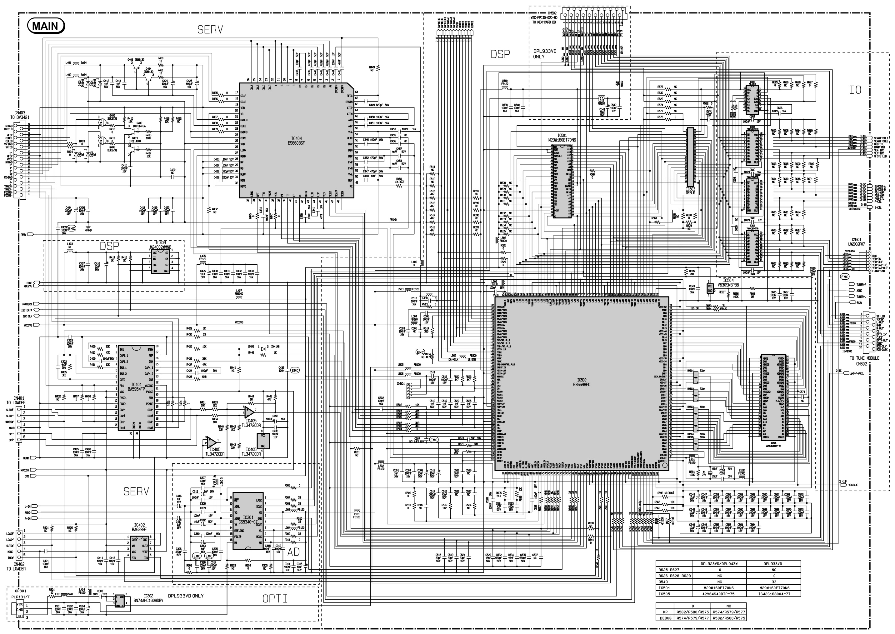
THOMSON DPL923VD, DPL933VD, DPL943W STEREO AMPLIFIER - DVD PLAYER SCHEMATIC DIAGRAM

Nominal output power:  4 x 50W:  2 x 100W

CONTROL / DISPLAY SCHEMATIC DIAGRAM

PT6315, HRM557BC5109, HT48R05


MAIN SCHEMATIC DIAGRAM: 1 OF 3

STA308A, STA515, BA4558F


MAIN SCHEMATIC: 2 OF 3

ES6603SF, BA5954FP, CS5340-C7, BA6289F, SN74AHC1GOBDBV, ES6698FD, M29W160ET70NG


MAIN SCHEMATIC: 3 0F 3

BU4052BF


MEMORY CARD READER SCHEMATIC DIAGRAM

GL816, 74VHC125M, 74LCX138M, 74LVX74MTR, CFCARD4312-23xxx


POWER SUPPLY [SMPS] SCHEMATIC DIAGRAM

L6565, VIPer53


Saturday, 12 September 2020

REPAIRING / SERVICING TV THOMSON T58ED10DHU-01B

Technical description and composition of the THOMSON T58ED10DHU-01B TV, panel type and modules used. The composition of the modules.
THOMSON LED
Model: T58ED10DHU-01B
Chassis / Version: 40-T31T0T-MAD2HG
Panel: V580HK1-LD6 rev.C1
T-CON: V420HK1-CS5, 40-M72312-MEC2HG
LED driver (backlight): integrated into PSU
PWM LED driver: L6599
MOSFET LED driver: ME15N10, 9N50
Power Supply (PSU): LK-PL580503B LKP-PL212
PWM Power: FAN7930, L6599, PWM SOT23-6
MOSFET Power: 12N50, 4N65, 9N50
MainBoard: 40-T31T0T-MAD2HG
IC MainBoard: SPI FLASH: W25Q64, AUDIO: TPA3110D2
Tuner: ST34WN-2T-B
Specifications T49D21SF-01B
THOMSON T58ED10DHU-01B
General recommendations for TV LCD LED repair
Possible manifestations of malfunctions
- TV THOMSON T58ED10DHU-01B does not turn on, does not respond to the remote control and control panel buttons, the indicators do not light up or flash.
In such cases, you should start looking for a fault in the circuits of the LK-PL580503B power supply. It is necessary to measure its secondary output voltages, and if they are absent, check the power switches (12N50, 4N65, 9N50) and rectifier diodes in the converters for a short circuit.
In the event of diode breakdowns in the secondary circuits, the converter can operate in an emergency mode of short circuit without output voltages, and in the event of a short circuit in the power elements of the primary circuit, the mains fuse and / or the current sensor in the source of the key usually breaks off.
Mos-Fet power switches used in switching power supplies sometimes fail due to a malfunction of any other elements that can disable it in the key mode, or create an excess of the maximum permissible key parameters. These can be elements supplying a PWM regulator, frequency setting or damper circuits, or elements of negative feedback in the stabilization circuit. PWM controllers FAN7930, L6599, PWM SOT23-6, in the absence of visible damage or outright short circuits between the terminals, are checked by replacing them with new ones, or known to be working properly.
- There is no image, there is sound, it reacts to the remote control. Or the image may appear for a second when turned on and disappear immediately.
In such cases, a malfunction of the LED panel backlighting elements is most likely. The reason for this may be an open circuit in the LED circuit, or a problem in stabilizing their power supply.
It should be remembered that it is not possible to determine an open circuit in the LED lines without disassembling the panels using a tester or multimeter without an additional device, for example, a current source. To open all PN junctions connected in series at once, a voltage of several tens of volts may be required. Then you need to open the panel and check each LED separately with a multimeter. If the capabilities of your multimeter do not allow opening the LED in the forward direction or dual LEds are used, then the PN transition of the emergency zener diode can indirectly serve as an indicator of serviceability. In the event of a malfunction of the LED-a, the PN-junction of the zener diode will either be cut off or broken into the K / Z.
- The indicator on the front panel blinks, the TV does not turn on in operating mode, does not respond to the remote control.

 If THOMSON T49D21SF-01B has no picture, but there is sound, often the display backlight simply does not work. Moreover, in LED TVs, the LEDs inside the panel usually fail, less often the LED driver.
In such cases, you can see a barely noticeable image with a successful hit of external light on the screen.
Replacing the LEDs requires disassembling the LCD panel - a process that requires experience and qualifications from the master. We do not recommend doing such work on your own to the owners of TVs and craftsmen who do not have experience in repairing LCD panels


If there is no image, and the backlight is on, the screen becomes slightly lighter when turned on, and in an open TV you can see light through the holes in the panel case.

In this case, the panel may also be faulty - damage to the strips, loops, for example, as a result of moisture ingress after unsuccessful washing of the screen, the T-CON (Timing Controller) board may be faulty. But often the main board MainBoard turns out to be faulty, a software failure is also possible.
Then, first of all, it is necessary to check the panel supply voltage, fuses on the T-CON board, as well as the supply and reference voltages of the column and line drivers - VGH, VGL, Vcom.

If these measurements are within normal limits, it is necessary to trace the passage of LVDS signals from the MainBoard with an oscilloscope, as well as synchronization signals to the loops with drivers.
Flooded or unsuccessfully washed screens of LED TVs can be restored, in about half of the cases, usually if significant damage has not formed in the loops and panel strips.

Repair or diagnostics of the 40-T31T0T-MAD2HG motherboard should begin with checking the stabilizers and power converters required to power the microcircuits and matrix. If necessary, you should update or replace the software (software). If it is not possible to replace the MB (SSB) board, it is necessary to check the serviceability of its elements - SPI FLASH: W25Q64, AUDIO: TPA3110D2. Defective components must be replaced.
Before changing the ST34WN-2T-B tuner, if it is not possible to tune to television channels, you should make sure that there are supply voltages, which must be measured at the corresponding tuner terminals and check the software for correctness. The pulses of the data exchange of the tuner with the processor can be monitored with an oscilloscope
Once again, we remind TV users: do not try to repair yourself without the appropriate knowledge, experience and the necessary qualifications! Trust the repair to professionals with sufficient experience in the field of electronic repair.

DOWNLOAD FIRMWARE FOR SPI FLASH  ----------->   THOMSON T58ED10DHU-01B, Main: 40-T31T0T-MAD2HG, Panel: V580HK1-LD6 rev.C1

DOWNLOAD SCHEMATIC DIAGRAM  / SERVICE MANUAL   ------------------>    LK-PL580503B Power supply

https://blogger.googleusercontent.com/img/b/R29vZ2xl/AVvXsEjS8YnKqFypcDlHVC-YQd6LFRCeLSDYEPUFh_WpzQI4GqIrn2zxQoGUKd-5YmV41GRfZk3WyaAefprcOINRkv4qh8LonPJ7psAY89xgry_Fsixtox_hIqg1YOgafcEfSnnqZYm1oVZ8i4k/s1600/40-T31T0T-MAD2HG_DCE.jpg

The appearance of the MainBoard 40-T31T0T-MAD2HG is shown in the figure below:
40-T31T0T-MAD2HG
External view of the power supply
The main features of the THOMSON T58ED10DHU-01B device:
Installed matrix (LED-panel) V580HK1-LD6 rev.C1.
Matrix control uses Timing Controller (T-CON) V420HK1-CS5.
A converter combined with a power supply is used to power the backlight LEDs, it is controlled by the L6599 PWM controller. The keys of the ME15N10, 9N50 type are used as power elements of the LED driver.
The formation of the necessary supply voltages for all nodes of the THOMSON T58ED10DHU-01B TV is carried out by the LK-PL580503B power module, or its analogs using FAN7930, L6599, PWM SOT23-6 microcircuits and 12N50, 4N65, 9N50 power switches.
MainBoard - the main board (motherboard) is a 40-T31T0T-MAD2HG module, using SPI FLASH chips: W25Q64, AUDIO: TPA3110D2 and others.
The ST34WN-2T-B tuner provides reception of television programs and tuning to channels.


PWM SMPS in SOT-23-6, SOT-26, TSOP-6 packages

In the circuitry of modern switching power supplies (SMPS), PWM controllers made in small-sized planar packages with six terminals have gained wide popularity. The enclosure type designation can be SOT-23-6, SOT-23-6L, SOT-26, TSOP-6, SSOT-6. The appearance and arrangement of the pins are shown in the figure below. In this case, the code marking LD7530A is shown on the left fragment of the picture.


 Pin assignment:
1 - GND. (Common wire).
2 - FB. (FeedBack - Feedback). Input for controlling the duration of pulses with a signal from the output voltage. Sometimes it can be labeled COMP (input comparator).
3 - RI / RT / CT / COMP / NC - Depending on the type of microcircuit, it can be used for a frequency-setting RC circuit (RI / RT / CT), or for organizing protection, as an input of a PWM trip comparator at a threshold value at its input, specified in the document. In some types of microcircuits, this input may not be used in any way (NC - No Connect).
4 - SENSE, otherwise CS (Current Sense) - Input from the current sensor at the source of the key.
5 - VCC - Input voltage supply and start of the microcircuit.
6 - OUT (GATE) - Output for controlling the gate (Gate) of the key.

Functionally, these regulators work on the principle of the previously popular xx384x PWM microcircuits, which have proven themselves well in terms of reliability and stability.

Some difficulties often arise when replacing or choosing an analog for such PWM regulators due to the use of code markings in the designation of the type of microcircuits. The situation is complicated by a large number of component manufacturers who do not always provide documentation to the mass access, just as not all manufacturers of finished devices supply repair service centers with diagrams, so repairmen often have to study real circuit solutions by installed components and wiring connections directly on the board.

In practice, PWM microcircuits and the marking code EAxxx and Eaxxx are often found. Official documentation for them was not found in the public domain, but discussions on the forums and pieces of pictures from PDF from System General, which publishes them as SG6848T and SG6848T2, have survived. The drawing is here placed left .


For the attention of the masters, here below are PDF datasheet tables compiled from information available on the Internet and PDF documents for the selection of analogues types when replacing the most common six-legged planar PWM with pinout pins: pin1 - GND, pin2 - FB (COMP), pin4 - Sense, pin5 - Vcc, pin6 - OUT ...
Their main difference is the application and purpose of pin 3. 


NamePart NumberFabricantMarking
SG6849SG684965TZFairchild / ON SemiBBxx
SG6849SG6849-65T, SG6849-65TZSystem GeneralMBxx EBxx
SGP400SGP400TZ System General AAKxx


 PWM controllers (PWM) with a 95-100 kOhm resistor on pin 3.

When applying the PWM listed below, the frequency should be set with the RT (RI) resistor from pin 3 to ground. Usually its nominal value is chosen 95-100 kOhm for a frequency of 65-100 KHz. For more details, see the here below attached documentation. PDF files are packed in RAR.


NamePart NumberFabricantMarking
AP3103AAP3103AKTR-G1Diodes IncorporatedGHL
AP8263AP8263E6R, A8263E6VRAiT SemiconductorS1xx
AT3263AT3263S6ATC Technology3263
CR6848CR6848SChip-Rail848H16
CR6850CR6850SChip-Rail850xx
CR6851CR6851SChip-Rail851xx
FAN6602RFAN6602RM6XFairchild / ON SemiACCxx
FS6830FS6830FirstSemi
GR8830GR8830CGGrenergy30xx
GR8836GR8836C, GR8836CGGrenergy36xx
H6849H6849NFHI-SINCERITY
H6850H6850NFHI-SINCERITY
HT2263HT2263MPHOT-CHIP63xxx
KP201
Kiwi Instruments
LD5530LD5530GL LD5530RLeadtrandxxt30 xxt30R
LD7531LD7531GL, LD7531PLLeadtrendxxP31
LD7531ALD7531AGLLeadtrendxxP31A
LD7535/ALD7535BL, LD7535GL, LD7535ABL, LD7535AGLLeadtrendxxP35-xxx35A
LD7550LD7550BL, LD7550ILLeadtrendxxP50
LD7550BLD7550BBL, LD7550BILLeadtrend xxP50B
LD7551LD7551BL/ILLeadtrendxxP51
LD7551CLD7551CGLLeadtrendxxP51C
NX1049XN1049TPXian-Innuovo49xxx
OB2262OB2262MPOn-Bright-Electronics62xx
OB2263OB2263MPOn-Bright-Electronics63xx
PT4201PT4201E23FPowtech4201
R7731R7731GE/PERichtek0Q=
R7731AR7731AGERichtekIDP=xx
SD4870SD4870TRSilan Microelectronics4870
SF1530SF1530LGTSiFirst30xxx
SG5701SG5701TZSystem GeneralAAExx
SG6848SG6848T, SG6848T1, SG6848TZ1, SG6848T2Fairchild / ON SemiAAHxx EAxxx
SG6858SG6858TZFairchild / ON SemiAAIxx
SG6859ASG6859ATZ, SG6859ATYFairchild / ON SemiAAJFxx
SG6859SG6859TZFairchild / ON SemiAAJMxx
SG6860SG6860TYFairchildAAQxx
SP6850SP6850S26RGSporton Lab850xx
SP6853SP6853S26RGB, SP6853S26RGSporton Lab853xx
SW2263SW2263MPSamWin
UC3863/GUC3863G-AG6-RUnisonic Technologies CoU863 U863G
XN1049XN1049, XN1049TPInnuovo Microelectronics49 xxx


 PWM controllers that use pin 3 differently.

When using the following PWM (PWM controllers), you should pay attention to pin 3, which can be used to organize protection - thermal or from overvoltage of the input voltage.
The frequency can be fixed at 65kHz, or set by the value of the capacitor at pin 3.
When replacing any microcircuits with analogs, carefully study the documentation. PDF files are packed in a RAR archive.


NamePart NumberFabricantMarking
AP3105/V/L/RAP3105KTR-G1, AP3105VKTR-G1, AP3105LKTR-G1, AP3105RKTR-G1Diodes IncorporatedGHN GHO GHP GHQ
AP3105NA/NV/NL/NRAP3105NAKTR-G1, AP3105NVKTR-G1, AP3105NLKTR-G1, AP3105NRKTR-G1Diodes IncorporatedGKN GKO GKP GKQ
AP3125A/V/L/RAP3125AKTR-G1, AP3125VKTR-G1, AP3125LKTR-G1, AP3125RKTR-G1Diodes IncorporatedGLS GLU GNB GNC
AP3125BAP3125BKTR-G1Diodes IncorporatedGLV
AP3125HA/HBAP3125HAKTR-G1, AP3125HBKTR-G1Diodes IncorporatedGNP GNQ
AP31261AP31261KTR-G1Diodes IncorporatedGPE
AP3127/HAP3127KTR-G1, AP3127HKTR-G1Diodes IncorporatedGPH GSH
AP3301AP3301K6TR-G1Diodes IncorporatedGTC
FAN6862FAN6862TYFairchild / ON SemiABDxx
FAN6863FAN6863TY, FAN6863LTY, FAN6863RTYFairchild / ON SemiABRxx
HT2273HT2273TPHOT-CHIP73xxx
LD7510/JLD7510GL, LD7510JGLLeadtrendxxP10 xxP10J
LD7530/ALD7530PL, LD7530GL, LD7530APL, LD7530AGLLeadtrendxxP30 xxxP30A
LD7532LD7532GLLeadtrendxxP32
LD7532ALD7532AGLLeadtrendxxP32A
LD7532HLD7532HGLLeadtrendxxP32H
LD7533LD7533GLLeadtrendxxP33
LD7536LD7536GLLeadtrendxxP36
LD7536RLD7536RGLLeadtrendxxP36R
LD7537RLD7537RGLLeadtrendxxP37R
LD7539C GLLD7539C GLLeadtrendxxP39C
ME8204ME8204M6GMicrOneME8204xx
NCP1250NCP1250ASN65T1G, NCP1250BSN65T1G, NCP1250ASN100T1G, NCP1250BSN100T1GON Semiconductor25xxxx
NCP1251NCP1251ASN65T1G, NCP1251BSN65T1G, NCP1251ASN100T1G, NCP1251BSN100T1GON Semiconductor5xxxxx
OB2273OB2273MPOn-Bright-Electronics73xx
R7735R7735AGE, R7735HGE, R7735GGE, R7735RGE, R7735LGERichtek
UC3873/GUC3873-AG6-R, UC3873G-AG6-RUnisonic TechnologiesU873 U873G


LED TV THOMSON T58ED10DHU-01B with LCD, diagonal size 49 "(124 cm) 16: 9 format. The declared brightness of the screen of 300 cd / m2 is provided by modern LED backlight LED. The ratio of maximum brightness to minimum (contrast) is not less 4000: 1 LCD panel uses Direct LED backlighting The design and technical capabilities of the TV allow viewing in high quality HD at a resolution of 1920x1080 pixels in graphics resolution in 1080p (Full HD). Supported media formats: MP3 , MPEG4, HEVC (H.265), Xvid, MKV, JPEG.
Speaker power of 10 W (2x5 W) is provided by two speakers. Uses NICAM stereo processing system and Sound Surround function.
External interface (communication with other devices) is supported by standard input and output connectors: antenna input (RF), AV, audio x2, component, VGA, HDMI x3, USB x2. A headphone jack is provided. The digital tuner has the ability to receive television channels in the DVB-T MPEG4, DVB-C, DVB-T2, DVB-S2 standards.
Overall dimensions: 1106x701x274 mm.
TV weight: 10.7 kg.
Attention! The panel of the THOMSON T58ED10DHU-01B LED TV is an expensive and unreliable element.
Do not allow any impact on the glass and pressure on the screen surface to avoid damage to the LED panel!

It is also unsafe for liquid to spill onto the screen. Sometimes one drop is enough if it drips down the glass onto the cables to make the TV unrepairable.