REPAIRING AND NOT THROWING AWAY

Richtige Fernseher haben Röhren!

Richtige Fernseher haben Röhren!

In Brief: On this site you will find pictures and technical information about Service Modes, Circuit Diagrams, Firmware Update procedure, Disassemble procedure, Universal remote control set-up codes, Troubleshooting and more....

If you go into the profession, you will obtain or have access to a variety of tech tips databases HERE IT IS Master Electronics Repair !.

These are an excellent investment where the saying: 'time-is-money' rules. However, to learn, you need to develop a general troubleshooting approach - a logical, methodical, method of narrowing down the problem. A tech tip database might suggest: 'Replace C536' for a particular symptom. This is good advice for a specific problem on one model. However, what you really want to understand is why C536 was the cause and how to pinpoint the culprit in general even if you don't have a service manual or schematic and your tech tip database doesn't have an entry for your sick TV or VCR.

While schematics are nice, you won't always have them or be able to justify the purchase for a one-of repair. Therefore, in many cases, some reverse engineering will be necessary. The time will be well spent since even if you don't see another instance of the same model in your entire lifetime, you will have learned something in the process that can be applied to other equipment problems.
As always, when you get stuck, checking out a tech-tips database may quickly identify your problem and solution.In that case, you can greatly simplify your troubleshooting or at least confirm a diagnosis before ordering parts.

Happy repairing!
Today, the West is headed for the abyss. For the ultimate fate of our disposable society is for that society itself to be disposed of. And this will happen sooner, rather than later.

How to use the site:

- If you landed here via any Search Engine, you will get what you searched for and you can search more using the search this blog feature provided by Google. You can visit more posts scrolling the left blog archive of all posts of the month/year,
or you can click on the main photo-page to start from the main page. Doing so it starts from the most recent post to the older post simple clicking on the Older Post button on the bottom of each page after reading , post after post.

You can even visit all posts, time to time, when reaching the bottom end of each page and click on the Older Post button.

- If you arrived here at the main page via bookmark you can visit all the site scrolling the left blog archive of all posts of the month/year pointing were you want , or more simple You can even visit all blog posts, from newer to older, clicking at the end of each bottom page on the Older Post button.
So you can see all the blog/site content surfing all pages in it.

- The search this blog feature provided by Google is a real search engine. If you're pointing particular things it will search IT for you; or you can place a brand name in the search query at your choice and visit all results page by page. It's useful since the content of the site is very large.

Note that if you don't find what you searched for, try it after a period of time; the site is a never ending job !

..............The bitterness of poor quality is remembered long after the sweetness of todays funny gadgets low price has faded from memory........ . . . . . .....
Don't forget the past, the end of the world is upon us! Pretty soon it will all turn to dust!

©2010, 2011, 2012, 2013, 2014 Frank Sharp - You do not have permission to copy photos and words from this blog, and any content may be never used it for auctions or commercial purposes, however feel free to post anything you see here with a courtesy link back, btw a link to the original post here , is mandatory.
All posts are presented here for informative, historical and educative purposes as applicable within fair use. NOTHING HERE IS FOR SALE !

Showing posts with label WELCHALLYN. Show all posts

Monday, 18 March 2019

WELCHALLYN 690 AND 692 SURE TEMP PLUS - THERMOMETER – - HOW TO CALIBRATE

WELCHALLYN  

690 AND 692

SURE TEMP PLUS - THERMOMETER –  - HOW TO CALIBRATE

CALIBRATION TESTING
  Whenever the clinical accuracy of the thermometer is in question, verify the instrument calibration. Your hospital biomedical department should establish a routine schedule for verifying instrument calibration. It is recommended the unit be tested semi-annually.
Cal-Key Verification
This method uses a fixed value to verify that the device is calibrated properly.
  • Remove any probe currently connected to the SureTemp Plus Thermometer.
  • Connect the SureTemp Plus Cal-Key (PN 06138-000).
  • Wait one minute for the device to enter Monitor mode and display the temperature.
  • The temperature should read 36.3 +/- 0.1ºC or 97.3 +/- 0.2ºF.
  • Remove the SureTempPlus Cal-Key.
  • Connect the original probe back to the device.
Model 9600 Calibration Tester Verification
This method is used to verify the calibration of the unit and probe pairing at two different temperatures. Use a verified thermometer from the Cal-Key Verification  and a functioning probe.
Caution: Store thermometers for testing in the same room as the 9600 Calibration Tester for approximately 30 minutes prior to testing to allow for thermal accommodation.
  • Plug in the Model 9600 Calibration Tester.
  • Choose the 96.4ºF/35.8ºC temperature setting. It is important to use the lower temperature setting first because the stabilization time from a high temperature to a low temperature takes about20 minutes. Stabilization from lower temperature to higher temperature requires about four ) minutes.
  • Wait for the Ready or green light to come on and stay on. This should take about six minutes.
  • Remove the probe from the well and clean it with either a 70% isopropyl alcohol solution, [a] 10% chlorine bleach solution, or a non-staining disinfectant. Let the probe air dry. Do not apply a probe cover. Place the thermometer in Monitor Mode. Refer to the thermometers Operator’s Manual.
  • Lift the rubber flap on the 9600 and insert the probe fully into the small hole on top of the 9600.
  • Wait 2 minutes for the probe temperature to fully stabilize. The temperature should read between 96.1ºF/35.6ºC and 96.7ºF/36.0ºC.
  • Remove the probe from the small hole on top of the 9600 and replace it in the probe well.
  • Change the temperature setting to the 106ºF/41.1ºC setting.
  • Wait for the Ready or green light to come on and stay on. This should take about four minutes.
  • Pull the probe from the well, but do not load a probe cover. Place the thermometer in Monitor Mode. Refer to the thermometer’s Operator’s Manual.
  • Lift the rubber flap on the Model 9600 Calibration Tester and insert the probe fully into the small hole on top of the tester.
  • Wait two minutes for the probe temperature to fully stabilize.
  • The temperature should read between 105.7ºF/40.9ºC and 106.3ºF/41.3ºC.
Model 9600 Plus Calibration Tester Verification
This method is used to verify the calibration of the unit and probe at three set point temperatures 36.0ºC (96.8ºF), 38.5ºC (101.3ºF), 41.0ºC (105.8ºF). Use a verified thermometer from the Cal-Key Verification (3.5.1) and a functioning probe.
Caution: Store thermometers for testing in the same room as the 9600 Plus Calibration Tester for approximately 30 minutes prior to testing to allow for thermal accommodation.
  1. Plug in the Model 9600 Plus Calibration Tester wall transformer to electrical power.
  2. The 36.0ºC (96.8ºF) temperature setting is selected when the calibration tester is first powered on.  If the calibration tester is all ready powered on, change the temperature setting on the Model 9600 Plus Calibration Tester to 36.0ºC (96.8ºF) with the up/down arrow key (Temperature will scroll through the 3 settings).  It is important to use the lower temperature setting first because the stabilization time from high temperature to low temperature takes about twenty (20) minutes. Stabilization time from a lower temperature to a higher temperature takes about six minutes.
  3. Wait for the displayed temperature to stop blinking. The actual temperature displayed blinks until the set temperature has stabilized.
  4. Remove the probe from the thermometer well and clean it with either a 70% isopropyl alcohol solution, a 10% chlorine bleach solution, or a non-staining disinfectant. Let the probe air dry for at least five minutes. Do not apply a probe cover. Place the thermometer in Monitor Mode. Refer to the thermometer’s Operator’s Manual.
  5. Rotate the dust cover down so the Thermistor Device Port is open/available, leaving the Ear Device Port covered, and insert the probe fully into the small hole on top of the Model 9600 Plus Calibration Tester.
  6. Wait for approximately one minute or until temperature on the thermometer is stable for ten seconds. Compare the thermometer’s temperature reading to the 9600 Plus’ calibration set point temperature. If the temperatures are within +0.1ºC (+0.2ºF), the thermometer is within calibration.
  7. Remove the probe from the probe well and place back into the thermometer probe well.
  8. Test all available thermometers for calibration verification at the current calibration set point temperature. Proceed to the next calibration set point temperature.  To scroll from one set point to the next, press and hold the temperature selection button until a beep is heard. The newly selected set point appears in the upper left corner of the LCD display. The device’s current temperature is displayed, will start to flash, and continue flashing until the cavity reaches the equilibrium at the new set point.
  9. When done testing all thermometers at all temperature set points, close the dust cover on the Model 9600 Plus Calibration Tester.

HOW TO TROUBLESHOOT WELCHALLYN 690 & 692 - DIGITAL THERMOMETER - ERROR CODES

HOW TO TROUBLESHOOT WELCHALLYN 690&692 -  - ERROR CODES

DIGITAL THERMOMETER

ERROR CODES

E0.1à  Excessive Heater Energy Try another predict cycle. If the problem persists replace the probe or contact Welch Allyn Customer Care.
E0.2 à  A/D Measurement out of range error.  Make sure the temperature is within the operating range of 50ºF/10ºC and 104ºF/40ºC  If the problem persists replace the probe or contact Welch Allyn Customer Care.
E0.4 à Probe Over Temperature (110ºF/43.3ºC).  Make sure the tip temperature is below 110ºF/43.3ºC.  If the problem persists replace the probe or contact Welch Allyn Customer Care.
E0.5 à  No Probe Temperature Rise. (The heater has no effect.).  Try another predict cycle.  If the problem persists replace the probe or contact Welch Allyn Customer Care.
E0.6 à Probe EEPROM read failure. (Bad EEPROM handshake.).  Verify the batteries are fresh.  If the problem persists replace the probe.
E0.7 à Probe EEPROM is un-initialized.  Verify that the batteries are fresh.  If the problem persists replace the probe.
E0.8 à EEPROM CRC Failure (EEPROM is corrupted.).  Verify that the batteries are fresh.  If the problem persists contact Welch Allyn Customer Care.
E0.9 à Bad probe calibration. Replace with a calibrated probe.
E4.0 à  PTB measurement out of range.  Try another predict cycle.  If the problem persists contact Welch Allyn Customer Care.
E4.1 à RCAL measurement out of range.  Try another predict cycle.  If the problem persists contact Welch Allyn Customer Care.
E4.2 à Reference power supply malfunction.  If the problem persists contact Welch Allyn Customer Care.
E4.3 à Device EEPROM save failure.  Verify that the batteries are fresh.  If the problem persists contact Welch Allyn Customer Care.
E4.4 à Device EEPROM starting handshake failure.  Verify that the batteries are fresh.  If the problem persists contact Welch Allyn Customer Care.
E4.5 à Device EEPROM response failure.  Verify that the batteries are fresh.  If the problem persists contact Welch Allyn Customer Care.
E4.6 à Transmit failure to the Device EEPROM.  Verify that the batteries are fresh.  If the problem persists contact Welch Allyn Customer Care.
E4.7 à Can’t initialize the device EEPROM.  If the problem persists contact Welch Allyn Customer Care.
E4.8 à Device was not calibrated Replace the device with a calibrated device.
E5.0 à Heater is not working properly.  Try another cycle. If the problem persists contact Welch Allyn Customer Care.
E5.2 à Heater fail-safe failure. Contact Welch Allyn Customer Care.
23 à Host Interface Error Try another predict cycle. If the problem persists contact Welch Allyn Customer Care.
26 à Invalid SureTemp mode Try another predict cycle.  If the problem persists contact Welch Allyn Customer Care.
29 à Battery Voltage Is Not Set Try another predict cycle. If the problem persists contact Welch Allyn Customer Care.
30 à Prediction mode Is Not Set Try another predict cycle.  If the problem persists contact Welch Allyn Customer Care.
71 à Device EEPROM acquire failure.  Try another predict cycle.  If the problem persists contact Welch Allyn Customer Care.
72 à Device EEPROM release failure.  Try another predict cycle.  If the problem persists contact Welch Allyn Customer Care.
73 à DEVICES EEPROM invalid pointer failure.  Try another predict cycle.  If the problem persists contact Welch Allyn Customer Care.
b^ à Battery voltage too high. Replace the batteries with batteries that provide less then 5.50 volts to the SureTemp Plus.
bv à Battery voltage too low. Replace the batteries with new batteries.  If problem does not go away and the batteries are known as good (>= 3.1 volts applied) contact Welch Allyn Customer Care.
A^! à Ambient temperature too high.  Move into an area where the temperature is between 50ºF/10ºC and 110ºF/43.3ºC and allow the thermometer to stabilize to ambient temperature.  If problem persists replace the probe or contact Welch Allyn Customer Care.
Av! à Ambient temperature too low.  Move into an area where the temperature is between 50ºF/10ºC and 110ºF/43.3ºC.  If the problem persists replace the probe or contact Welch Allyn Customer Care.  Patient Temperature out of range. < 80ºF/26.7ºC or > 110ºF/43.3ºC.  Make sure the probe is positioned properly within the patient body site, with good tissue contact, and/or verify the patient's temperature is in the range.  Try another temperature cycle with the probe positioned properly.  If the problem persists, replace the probe or contact Welch Allyn Customer Care.
Instrument Errors
Instrument Circuitry errors are generated from internal test failures. Instrument errors are displayed as an instrument with an X through it and an error code in the temperature field. In most cases this will represent a broken instrument that needs replacing and the code will tell what error was detected.
Probe Errors
The probe or probe connector can generate errors. Probe errors are displayed as a probe with an X through it and an error code in the temperature field. In most cases this will represent a broken probe that needs replacing and the code will tell what error was detected.  Temperature measuring is prohibited until the error is cleared.
Patient Temperature Out of Range
Patient Temperature Out of Range errors occur when the patient temperature is above 110.0° F or below 80.0° F. During this error, the entire body (head, torso, and legs) displays by blinking with a solid up or down arrow and a thermometer bulb.
Ambient Temperature Out of Range
Ambient Temperature errors occur when the ambient probe temperature is above 104.0° F or below 50.0° F. During an ambient temperature error, the display in the temperature number field shows a capital “A” followed by a blinking up or down arrow and a blinking thermometer bulb.

Saturday, 16 March 2019

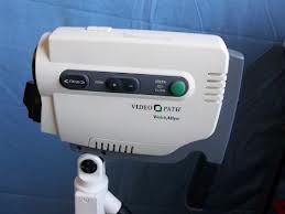
HOW TO DISASSEMBLE WELCHALLYN VIDEO COLPOSCOPE - MEDICAL EQUIPMENT

HOW TO DISASSEMBLE WelchAllyn VIDEO COLPOSCOPE - Medical Equipment


CAUTION: Lamp area will be hot immediately after lamp operation.

  • Slide access door away from housing assembly.
  • Remove connector from lamp.  Note: Connector has 2 different size holes.
  • Slide lamp away from lamp housing assembly.
  • Observe the correct path for lamp wires.
  • Remove the 4-torx screws from left outer housing with a T-15 screwdriver.
  • Reach under label and peel away from housing.
  • Open outer housing this way to avoid stress on ribbon cable.
  • Disconnect locking connector.
  • Observe the correct positioning of ribbon cable in left outer housing.
  • Remove the 6 Phillips head screws that hold the switch PCB to the left outer housing.
  • The switch pad is attached to the left and right switch PCB by rubber tabs. Gently pull tabs away from switch PCB.
  • Logic PCB is removed by removing connectors and 4 Phillips head screws. Note connector orientation and wire harness path on Logic PCB. Fan wire exits on left side.
  • Gently pull the light director from focusing sleeve.
  • Observe the positioning of plastic tie wrap.  This tie wrap serves as a polarizing filter brake.
  • Unscrew focusing sleeve from lamp housing. Note orientation of light director, filter and focusing sleeve.
  • The glass rod/ferrule assembly may come out with the focusing sleeve.  Do not lose the UV filter in the end of the brass ferrule.
  • Camera chassis removal, from the right housing is accomplished by removing the 3 torx T-15 screws from right outer housing.
  • Remove camera from right housing.
  • Unscrew outer lens.
  • Remove lens gasket and lens filter. Note lens filter tab orientation.
  • Removal of ballast PCB is accomplished by removing connector and 4 screws.
  • Unscrew three Phillips head screws for Sony camera removal.
  • Gently pull camera from chassis.
Note the orientation of fiber washer. During reassembly make sure fiber washer is over the thermal cut out as shown.  Improper installation will result in power supply damage. Use thread lock 222 on the screw.  Do not over tighten.

TROUBLESHOOTING - WELCHALLYN - VIDEO COLPOSCOPE [MEDICAL EQUIPMENT]

TROUBLESHOOTING - WelchAllyn - Video Colposcope [Medical Equipment]


TROUBLESHOOTING CHART

CLICK ON THE CHART TO ZOOM