REPAIRING AND NOT THROWING AWAY

Richtige Fernseher haben Röhren!

Richtige Fernseher haben Röhren!

In Brief: On this site you will find pictures and technical information about Service Modes, Circuit Diagrams, Firmware Update procedure, Disassemble procedure, Universal remote control set-up codes, Troubleshooting and more....

If you go into the profession, you will obtain or have access to a variety of tech tips databases HERE IT IS Master Electronics Repair !.

These are an excellent investment where the saying: 'time-is-money' rules. However, to learn, you need to develop a general troubleshooting approach - a logical, methodical, method of narrowing down the problem. A tech tip database might suggest: 'Replace C536' for a particular symptom. This is good advice for a specific problem on one model. However, what you really want to understand is why C536 was the cause and how to pinpoint the culprit in general even if you don't have a service manual or schematic and your tech tip database doesn't have an entry for your sick TV or VCR.

While schematics are nice, you won't always have them or be able to justify the purchase for a one-of repair. Therefore, in many cases, some reverse engineering will be necessary. The time will be well spent since even if you don't see another instance of the same model in your entire lifetime, you will have learned something in the process that can be applied to other equipment problems.
As always, when you get stuck, checking out a tech-tips database may quickly identify your problem and solution.In that case, you can greatly simplify your troubleshooting or at least confirm a diagnosis before ordering parts.

Happy repairing!
Today, the West is headed for the abyss. For the ultimate fate of our disposable society is for that society itself to be disposed of. And this will happen sooner, rather than later.

How to use the site:

- If you landed here via any Search Engine, you will get what you searched for and you can search more using the search this blog feature provided by Google. You can visit more posts scrolling the left blog archive of all posts of the month/year,
or you can click on the main photo-page to start from the main page. Doing so it starts from the most recent post to the older post simple clicking on the Older Post button on the bottom of each page after reading , post after post.

You can even visit all posts, time to time, when reaching the bottom end of each page and click on the Older Post button.

- If you arrived here at the main page via bookmark you can visit all the site scrolling the left blog archive of all posts of the month/year pointing were you want , or more simple You can even visit all blog posts, from newer to older, clicking at the end of each bottom page on the Older Post button.
So you can see all the blog/site content surfing all pages in it.

- The search this blog feature provided by Google is a real search engine. If you're pointing particular things it will search IT for you; or you can place a brand name in the search query at your choice and visit all results page by page. It's useful since the content of the site is very large.

Note that if you don't find what you searched for, try it after a period of time; the site is a never ending job !

..............The bitterness of poor quality is remembered long after the sweetness of todays funny gadgets low price has faded from memory........ . . . . . .....
Don't forget the past, the end of the world is upon us! Pretty soon it will all turn to dust!

©2010, 2011, 2012, 2013, 2014 Frank Sharp - You do not have permission to copy photos and words from this blog, and any content may be never used it for auctions or commercial purposes, however feel free to post anything you see here with a courtesy link back, btw a link to the original post here , is mandatory.
All posts are presented here for informative, historical and educative purposes as applicable within fair use. NOTHING HERE IS FOR SALE !

Saturday 16 March 2019

CANON LBP1120 HOW TO DISASSEMBLE MAIN UNIT - - LASER PRINTER

CANON LBP1120

HOW TO DISASSEMBLE MAIN UNIT -  - LASER PRINTER 


ARRANGEMENT OF COMPONENT
[1] Rear cover
[2] Right cover
[3] Left cover
[4] Upper cover
[5] Cartridge cover

[6] Pickup tray
Rear Cover
Remove the screw.
Locate the claw under the area indicated by an arrow. Open the bottom of the left/right side of the rear cover, and slide it to the front; free the claw, and lift the rear cover to detach.
Right Cover
Remove the rear cover.
Open the cover of the cartridge assembly.
Remove the screw and, free the claw under the area indicated by an arrow, and free the hook; then, detach the right cover.
Left Cover
Remove the screw
Open the cover of the cartridge assembly.
Remove the screw and, free the law under the area indicated by an arrow, and free the hook; then, detach the left cover.
Upper Cover
Remove the rear cover and the left/right cover.
Disconnect the connector J203 from the engine controller PCB; then, free the harness from the guide.
Remove the 2 screws, and free the 2 claws; then, detach the upper cover.
Cartridge Cover
Remove the rear cover and the left/right cover.
Open the cartridge cover.
Force the front cover down to detach.
While pushing the claw, detach the cartridge cover from the arm.
Slide the shaft, and detach the cartridge cover.
Pickup Tray
Remove the rear cover.
Slide up the pickup tray to detach.


CROSS SECTION
CLICK ON THE PICTURES TO ZOOM
[1]: Face-down delivery roller.
[2]: Fixing film unit
[3]: EP-22 cartridge
[4]: Primary charging roller
[5]: Laser/scanner unit
[6]: Pick-up roller
[7]: Separation pad
[8]: Feed roller
[9]: Developing cylinder
[10]: Transfer charging roller
[11]: Photosensitive drum
[12]: Pressure roller
[13]: Fixing delivery roller
Remove the rear cover, left/right cover, and upper cover.
To enable the disconnection of the connectors, peel off the Warning label (laser) halfway.
Disconnect the 2 connectors, and remove the 4 screws; then, detach the Laser/scanner unit.
Do not disassemble the Laser/scanner unit; you will not be able to adjust it in the field.
There is no Warning label (laser) used on the Laser/scanner unit offered as a service part. If you are replacing the assembly, remove the
label from the existing assembly, and transfer it to the new assembly. Or, use the newly available Warning label (service part). Be sure also to fully hide the connector openings from view.
Drive Assembly
Remove the rear cover and the left/right cover.
Remove the 2 screws and 2 screws equipped with a washer. Slide out the drive assembly slightly, and disconnect the connectors to remove the drive assembly.


Feed Assembly
Remove the engine controller assembly.
Free the 2 claws, and remove the 2 gears and the screw.
Push the 2 claws, and remove the bushing.
Remove the 2 screws, and disconnect the 2 connectors; then, remove the feed assembly.
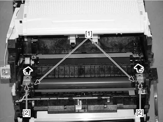
Delivery Assembly
Open the cartridge cover.
Remove the boss, and remove the face-down delivery roller bushing; then, slide the face-down delivery roller to the right to detach.
Pull the pressure release lever to the front to release the pressure.
Remove the 2 screws, and slide the delivery assembly to the right to detach.
Fixing Film Unit
Remove the rear cover and the left/right cover.
Remove the delivery assembly.
With the pressure release lever shifted up, push down on the fixing pressure unit (left/right) from above; then, slide it to the rear to detach.
Disconnect the connector.
Disconnect the connector, and free the harness from the harness guide.
Remove the fixing film unit.