LG 47LG90 LED LCD TV - POWER SUPPLY TROUBLESHOOTING

SMPS PWB OPERATIONAL TROUBLESHOOTING
Ac voltage is supplied to the Power Supply at Connector SC100. AC Detect is generated and should be present at connector P201 pin 8 (5V). The AC input also generates a Hot Ground primary power supply that runs in two states, Stand-By (156V) and Run (386V) measured at Fuse F101. This primary voltage develops all other voltages that are output from the power supply. During Stand-By, the 5 Volt Standby should be present at connector P201, Pins 9,10,11 or 12. If Missing remove AC Power and unplug Connector P201, apply AC Power and recheck for presence of both 5 Volt Standby and AC Detect. Loss of either 5 Volt Standby or AC Detect would be a Power Supply Failure. Presence of 5 Volt Standby and AC Detect would be an indication of a failure on the Main Board. Suspect a possible short circuit loading the supply. Remember to observe the Front Power Indicating LED this may save some time. A lit LED most likely indicates the Stand-By 5V voltage is present.
A
loss of the AC detect line will prevent the front power LED from lighting, because,
it is driven by I2C bus communication.
The Main Board sends two commands to the
Power Supply Board one being PWR the other is INV ON. These two voltages are
used to control the power on turn on sequence. First via PWR (Pin 19) also
known as RL ON activates the 24Volt to the Inverters and the 16 Volt and 12 Volt
lines to the Main board. The 2nd command is INV ON. It passes
through the Power Supply to the Inverter Boards to turn them on. If either command voltage (PWR or INV ON) is
missing it will result in a no picture symptom. These voltages can easily be
checked with the voltmeter. Remove AC Power, unplug Connector P204, reapply AC
Power and press the ON-OFF Button on either the Remote Control or Power Button
on the Unit. Watch for the Power ON LED to change color from red to blue. This
is an indication the PWR Signal was created on the Main board. Check P800 or
P201 pin 19 for the PWR command (2.8V) to the Power Supply. Check P201 for 16V
(Pins 1 or 2)and 12V (Pins 5 or 6). Check P204/P205 Pins 1,2,3,4 or 5 for the presence
of the 24 Volt Supply. Confirm Pin 12 of P204/P205 went to 3.3V. This is the
INV ON signal needed to turn on the Inverters and light the backlight LEDs.
Following the simple steps can easily solve
problems with either voltage.LOW VOLTAGE TEST
AC Should not be applied at any time while adding resistors or while unplugging connectors as damage to the circuit PWB may occur.
- The SMPS PWB “MUST” be producing STBY 5V on pins 9, 10, 11 or 12 (5V).
- The SMPS PWB “MUST” be generating ACD (AC Detect) Pin 18 check for 5V.
- If the conditions (a) or (b) above are not met, the SMPS PWB is defective and must be replaced. There is no need to continue with the test.
- Unplug P800 on Main PWB and P204, P205 to the inverters.
TEST
1:
- Add a 10K resistor between (5V STBY) pin 9, 10, 11 or 12 and Pin 19 (PWR). Apply AC. This will turn on the power supply.
- Check that the 16V and 12V power supplies are turned on, P201 (16V pins 1 and 2) (12V pins 5 and 6)
- Check that the 24V (Inverter B+) is turned on P205 and P204 pins 1~5.
- Remove AC power. Reinsert the plugs P204/P205 to the inverters.

PWB BACKLIGHTS TEST
P800
Connector disconnected from the Main PWB. Apply AC after adding jumper.
Continue
if the 1st test was successful. Leave original 10K resistor in
place.
- Add a jumper wire between Pin 20 (INV On/Off) to Pin 19 (PWR).
- Apply AC Power. This simulates a Power On and Backlight On command. Observe the Backlights.
- If normal, the backlights should turn on. (They will be dim.)
- If no backlight activity, reconfirm the 24V is being generated and output on P204/P205 connector Pins 1~5. If not, unplug P204 or P205 and recheck. If not SMPS is defective. If yes, Inverter is loading down the 24V line.
- Confirm the INV On/Off line Pin 20 is going to 3V. Confirm the Inverter On command is leaving P204/P205 Pin 12.
- If all the above is normal, refer to the Inverter section to check voltages on the Inverters.

POWER SUPPLY PWB BACK-LIGHTS TEST
Using
the Power Supply (SMPS) Voltage Label (Silk Screen)
Using the (Silk Screen) Label can assist when
dealing with an over current situation. Normal loads will keep the current reading
under the Label’s maximum currents output reading.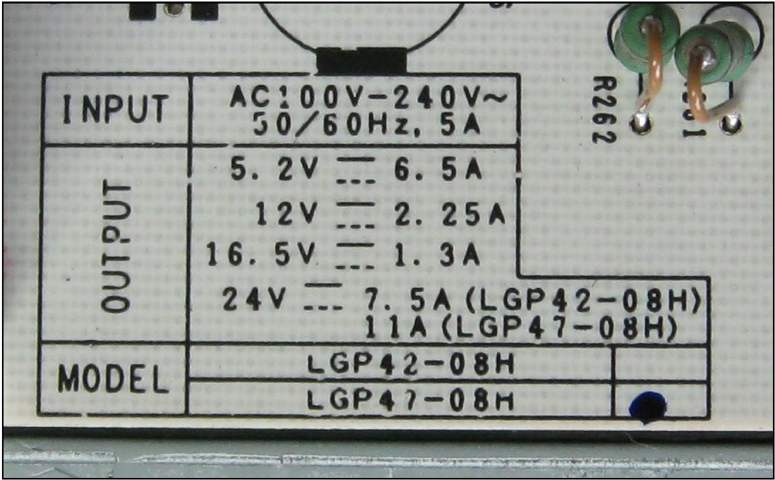
- The AC input Fuse draws a maximum current 5 Amps.
- The 5.2V output (Stand by 5V) maximum output current 6.5 Amps.
- The 12V output (Video Processing and T-CON board B+) maximum output current 2.25 Amps.
- The 16.5V output (Audio) maximum output current 1.3 Amps.
- The 24V output (Inverters) maximum output current 11 Amps.
CONNECTOR [P201] VOLTAGE & RESISTANCE


CONNECTOR [P204]

