REPAIRING AND NOT THROWING AWAY

Richtige Fernseher haben Röhren!

Richtige Fernseher haben Röhren!

In Brief: On this site you will find pictures and technical information about Service Modes, Circuit Diagrams, Firmware Update procedure, Disassemble procedure, Universal remote control set-up codes, Troubleshooting and more....

If you go into the profession, you will obtain or have access to a variety of tech tips databases HERE IT IS Master Electronics Repair !.

These are an excellent investment where the saying: 'time-is-money' rules. However, to learn, you need to develop a general troubleshooting approach - a logical, methodical, method of narrowing down the problem. A tech tip database might suggest: 'Replace C536' for a particular symptom. This is good advice for a specific problem on one model. However, what you really want to understand is why C536 was the cause and how to pinpoint the culprit in general even if you don't have a service manual or schematic and your tech tip database doesn't have an entry for your sick TV or VCR.

While schematics are nice, you won't always have them or be able to justify the purchase for a one-of repair. Therefore, in many cases, some reverse engineering will be necessary. The time will be well spent since even if you don't see another instance of the same model in your entire lifetime, you will have learned something in the process that can be applied to other equipment problems.
As always, when you get stuck, checking out a tech-tips database may quickly identify your problem and solution.In that case, you can greatly simplify your troubleshooting or at least confirm a diagnosis before ordering parts.

Happy repairing!
Today, the West is headed for the abyss. For the ultimate fate of our disposable society is for that society itself to be disposed of. And this will happen sooner, rather than later.

How to use the site:

- If you landed here via any Search Engine, you will get what you searched for and you can search more using the search this blog feature provided by Google. You can visit more posts scrolling the left blog archive of all posts of the month/year,
or you can click on the main photo-page to start from the main page. Doing so it starts from the most recent post to the older post simple clicking on the Older Post button on the bottom of each page after reading , post after post.

You can even visit all posts, time to time, when reaching the bottom end of each page and click on the Older Post button.

- If you arrived here at the main page via bookmark you can visit all the site scrolling the left blog archive of all posts of the month/year pointing were you want , or more simple You can even visit all blog posts, from newer to older, clicking at the end of each bottom page on the Older Post button.
So you can see all the blog/site content surfing all pages in it.

- The search this blog feature provided by Google is a real search engine. If you're pointing particular things it will search IT for you; or you can place a brand name in the search query at your choice and visit all results page by page. It's useful since the content of the site is very large.

Note that if you don't find what you searched for, try it after a period of time; the site is a never ending job !

..............The bitterness of poor quality is remembered long after the sweetness of todays funny gadgets low price has faded from memory........ . . . . . .....
Don't forget the past, the end of the world is upon us! Pretty soon it will all turn to dust!

©2010, 2011, 2012, 2013, 2014 Frank Sharp - You do not have permission to copy photos and words from this blog, and any content may be never used it for auctions or commercial purposes, however feel free to post anything you see here with a courtesy link back, btw a link to the original post here , is mandatory.
All posts are presented here for informative, historical and educative purposes as applicable within fair use. NOTHING HERE IS FOR SALE !

Showing posts with label DURABAND. Show all posts

Tuesday, 2 April 2019

DURABAND DBTV1902 - SERVICE MODE - FACTORY RESET

DURABAND DBTV1902 - SERVICE MODE - FACTORY RESET

How to enter Service Mode_Memory IC replacement & adjustments _ Default Data Values _ Factory Reset.
SERVICE MODE
This unit provided with the following SERVICE MODES so you can repair, examine and adjust easily.
* To enter the Service Mode, press both set key and remote control key for more than 1 second.
CONFIRMATION OF HOURS USED
POWER ON total hours can be checked on the screen. Total hours are displayed in 16 system of notation.
* Set the VOLUME to minimum.
* Press both VOL. DOWN button on the set and Channel button (6) on the remote control for more than 1 second.
* After the confirmation of using hours, turn off the power.
REPLACING EEPROM (MEMORY) IC
If a service repair is undertaken where it has been required to change the MEMORY IC, the following steps should be taken to ensure correct data settings while making reference to TABLE.
1. Enter DATA SET mode by setting VOLUME to minimum.
2. Press both VOL. DOWN button on the set and Channel button (6)on the remote control for more than 1 second.
3. ADDRESS and DATA should appear as FIG. ADDRESS is now selected and should "blink". Using the SET + or - keys on the remote, step through the ADDRESS until required ADDRESS to be changed is reached.
4. Press ENTER to select DATA. When DATA is selected, it will "blink".
5. Again, step through the DATA using SET + or - until required DATA value has been selected.
6. Pressing ENTER will take you back to ADDRESS for further selection if necessary.
7. Repeat steps 3 to 6 until all data has been checked.
8. When satisfied correct DATA has been entered, turn POWER off (return to STANDBY MODE) to finish DATA input.
The unit will now have the correct DATA for the new MEMORY IC.
On-Screen Display Adjustment
* In the condition of NO indication on the screen.
8 Press the VOL. DOWN button on the set and the Channel button (9) on the remote control for more than 1 second to appear the adjustment mode on the screen as shown in Fig.
Use the Channel UP/DOWN button or Channel button (0-9) on the remote control to select the options shown in Fig.
Press the MENU button on the remote control to end the adjustments.
Confirmation of Fixed Value.
Check if the fixed values of the each adjustment items are set correctly referring below.

DURABAND DBTV 1902 SMPS (POWER SUPPLY) - CIRCUIT DIAGRAM

SMPS (Power Supply) - Circuit Diagram_ DURABAND DBTV 1902

Duraband DBTV1902 _ Power supply Section Circuit Diagram [Schematic]
SMPS [CLICK ON THE CIRCUIT DIAGRAM TO MAGNIFY]
PWB_FOIL SIDE

Monday, 1 April 2019

DURABAND DBTV1901- HOW TO ENTER SERVICE MODE - SCHEMATIC DIAGRAM

DURABAND DBTV1901- HOW TO ENTER SERVICE MODE - SCHEMATIC DIAGRAM

How to enter service mode to Duraband DBTV1901_Schematic Diagram_Memory IC replacemant & adjustments. [Universal Remote Control Set-up Codes]
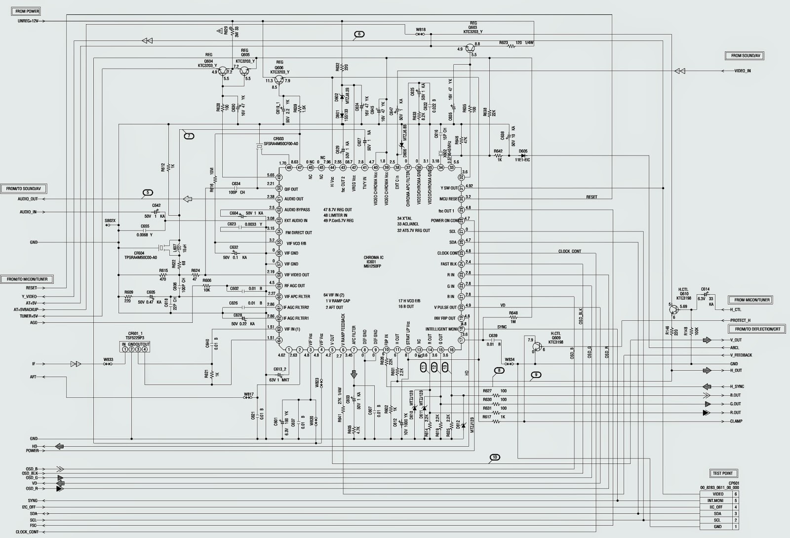
Semi-conductors (ICs) used _ AN5522_2SD2627LS-CBC11(Hor: Output)_M61250FP(Chroma)_OEC7073A(Micon)_S-24C02BDP-1A(Memory)
SERVICE MODE
To enter the Service Mode, press both set key and remote control key for more than 1 second
CONFIRMATION OF HOURS USED
* POWER ON total hours can be checked on the screen. Total hours are displayed in 16 system of notation.
* Set the VOLUME to minimum.
* Press both VOL. DOWN button on the set and Channel button (6)on the remote control for more than 1 second.
* After the confirmation of using hours, turn off the power.
REPLACING EEPROM (MEMORY) IC
If a service repair is undertaken where it has been required to change the MEMORY IC, the following steps should be taken to ensure correct data settings.
1. Enter DATA SET mode by setting VOLUME to minimum.
2. Press both VOL. DOWN button on the set and Channel button (6) on the remote control for more than 1 second.  ADDRESS and DATA should appear.
3. ADDRESS is now selected and should "blink". Using the SET + or - keys on the remote, step through the ADDRESS until required ADDRESS to be changed is reached.
4. Press ENTER to select DATA. When DATA is selected, it will "blink".
5. Again, step through the DATA using SET + or - until required DATA value has been selected.
6. Pressing ENTER will take you back to ADDRESS for further selection if necessary.
7. Repeat steps 3 to 6 until all data has been checked.
8. When satisfied correct DATA has been entered, turn Power Off (return to Standby Mode) to finish the DATA input.  The unit will now have the correct DATA for the new memory IC.
On-Screen Display Adjustment
> In the condition of NO indication on the screen.
* Press the VOL. DOWN button on the set and the Channel button (9) on the remote control for more than 1 second to appear.
* Use the Channel UP/DOWN button or Channel button (0-9)on the remote control to select the options.
* Press the MENU button on the remote control to end the adjustments.
SCHEMATIC (Circuit Diagram)
SYSTEM CONTROL & MEMORY
Horizontal & Vertical Scan Output
CHROMA
SMPS
CLICK ON THE SCHEMATICS TO ZOOM IN
Universal remote control set-up codes: 0101 0135 0767

Saturday, 30 March 2019

HAIER BH2004D (AMERICA) – DURABAND CTV – HOW TO ENTER SERVICE MODE-DEFAULT DATA VALUES – SCHEMATIC DIAGRAM

HAIER BH2004D (America) – DURABAND CTV – HOW TO ENTER SERVICE MODE-DEFAULT DATA VALUES – SCHEMATIC DIAGRAM

Haier BH-2004D CTV - How to enter service mode - Memory IC replacement_ Default Data Values _ Full Circuit Diagram.
 
MEMORY IC REPALCEMENT and SERVICE MODE ENTRY
* Standby off.  Switch the power off and unplug the power cord from AC outlet.
* Replace the IC.  Be sure to use memory IC written with the initial data values.
* Standby on.  Plug the power cord into the AC outlet and switch the power on.
* Check and set the System Default Value:
* Press “Mute” “Call” “-\--“ “Call” “Mute” buttons in sequence to enter into factory mode [Service Mode].
If the memory IC haven’t been written with the initial data, press “Program+” / “Program –“ to select the item “Init” and press “Volume +” / “Volume –“ to start initialize the memory IC
Check the setting value of the System default value.  If the value is different, select items by “Pr+ / Pr—“ keys and set value by Vol + / Vol – keys.
Press Exit button to return to normal screen.
 
FACTORY SET VALUES [DEFAULT DATA VALUES TO MEMORY IC]
SCHEMATIC DIAGRAM -Full
CLICK ON THE PICTURES TO ZOOM IN

Monday, 18 March 2019

DURABAND - T6605VF – T6705VF – TV/VCR COMBO - VCR MECHANISM SERVICE

DURABAND - T6605VF – T6705VF – TV/VCR COMBO - VCR MECHANISM SERVICE

VCR MECHANISM ALIGNMENT
Method for Manual Tape Loading/Unloading
To load a cassette tape manually:
  • Disconnect the AC plug.
  • Remove the Top Case and Front Assembly.
  • Insert a cassette tape. Though the tape will not be automatically loaded, make sure that the cassette tape is all the way in at the inlet of the Cassette Holder. To confirm this, lightly push the cassette tape further in and see if the tape comes back out, by a spring motion, just as much as you have pushed in.
  • Turn the LDG Belt in the appropriate direction shown in Fig for a minute or two to complete this task.
To unload a cassette tape manually:
  • Disconnect the AC plug.
  • Remove the Top Case and Front Assembly.
  • Make sure that the Moving guide preparations are in the Eject Position.
  • Turn the LDG Belt in the appropriate direction shown in Fig. until the Moving guide preparations come to the Eject Position. Stop turning when the preparations begin clicking or cannot be moved further. However, the tape will be left wound around the cylinder.
  • Turn the LDG Belt in the appropriate direction continuously, and the cassette tape will be ejected.  Allow a minute or two to complete this task.
Method to place the Cassette Holder in the tape-loaded position without a cassette tape
  • Disconnect the AC Plug.
  • Remove the Top Case and Front Assembly.
  • Turn the LDG Belt in the appropriate direction shown in Fig. M1. Release the locking tabs shown in Fig. and continue turning the LDG Belt until the Cassette Holder comes to the tape-loaded position. Allow a minute or two to complete this task.
CLICK ON PICTURES TO ZOOM

Monday, 25 February 2019

DURABAND - DBVT1341 SERIES A & MEMOREX [SERVICE MODE]

DURABAND - DBVT1341 Series A & MEMOREX [SERVICE MODE]


TO ENTER SERVICE MODE


The unit provides with the following Service Modes, so you can repair, examine and adjust easily.

  • Unplug the AC cord till lost all clock time.  
  • Press and Hold "Vol-" button on the front panel of the TV & remote control unit simultaneously. 
  • The both pressing of set key and the remote control key will not be possible if clock has been set.
CONFIRMATION OF HOURS USED
  1. Set the Volume to Minimum.
  2. While holding down Volume button on the front cabinet, press key [6] on the remote control simultaneously.  
  3. After confirming of using hours, turn Off Power.
DISPLAY Window.

 INIT  00  83 => INITIAL SETTING CONTENT OF ,MEMORY IC.

POWER ON   0010 => POWER ON TOTAL HOURS.
PLAY/RECORD => PLAY/RECORD TOTAL HOURS.
 [16*16*16*thousand digit value] +  [ 16*16*hundreds digit value] + [16* tens digit value] + [ones digit value]

SET KEY => REMOTE KEY  =>  OPERATIONS.

Volume Minimum => 0 => Releasing of V-Chip password.
Vol min => 1 = Initialization of factory ( Do not use this for normal service).
Vol min => 2 => Horizontal position of OSD.
Vol min => 3 => Adjust the PG shifter automatically.
Vol min => 4 => Adjust the PG sifter manually.
Vol min => 5 => Adjusting the tracking to center position.
Vol min => 6 => Power On total hours and Play|Record total hours displayed on the screen.
Vol min => 8 => Writing of EEPROM initial data. (do not use this for normal service).
Vol min => 9 => Display of adjustment menu on screen.

METHOD  =>    OPERATIONS

Method:  Press the ATR button on the remote control for more than 2 seconds during PLAY.
Operation:  Adjusting the tracking to center position.
Method: make a short circuit between the test points of "Service" and Ground"
Operation:  The EOT | BOT | REEL SENSOR do not work at this moment.

Saturday, 23 February 2019

DURABAND - T6609BK REPAIR HELP TV-VCR COMBINATION

  TO SETUP SERVICE MODE   DURABAND - T6609BK REPAIR HELP TV-VCR COMBINATION

  1. Turn the Power ON, by the front panel Power ON | OFF switch on the set.
  2. Press [Standby => 2 => 7 => 1 => Mute] buttons on the remote in sequence, within [5] seconds.
  3. To Exit from service mode, press [Standby | On] button on the remote control.
TO SETUP OPTION CODE.
  • Enter the service mode.
  • Press "Status" button on the remote control unit.  The option code appears on the display.
  • If needed, input the option code (0128), using number buttons on the remote control.
  • To reset the Software, press "Pause" and (5) buttons on the remote control.  The option code is changed.
TO INITIALIZE THE SET
  1. Turn the Power On, by using the front panel Power ON | OFF switch.
  2. To enter service mode, press [Standby / On => 2 => 7 => 1 => Mute] buttons on the remote control, in that order within [5] seconds.
  3. To cancel the Service Mode, press "Standby | On] button on the remote control.
  4. Press [sleep] button on the remote control unit to start initialization.  During initialization OSD indication (digits) on the four corners of the TV screen blinks to white.  After initialization, OSD indication lights to Red.
  5. Turn the Power Off, by pressing Main Power button on the TV unit, and 'unplug' the AC cord from AC outlet.
MECHANICAL TROUBLE INDICATIONS

  • If the monitor is turned On right after the Mechanical Malfunction ocurs on POWER/SAFETY/X-RAY is turned On, display the following character to show malfunction after the Eject display.


  1. Reel Malfunction   =>  R
  2. Drum Malfunction   => D
  3. Cassette Loading Malfunction  => C
  4. Tape Loading Malfunction  => T
  5. P-Safety-1  => 1
  6. P-Safety-2  => 2
  7. X-Ray  => X

DURABAND - T6609BK REPAIR HELP TV-VCR COMBINATION


MALFUNCTION EVALUATION METHODS

X-RAY PROTECT

If X-Ray port becomes continuously 2.5V or more for 120ms, the unit shall immediately turn off the Power/Monitor and will switch over to the mechanical malfunction mode with Power Off.  To turn from this mode shall become possible only by Power key, as the case of the Mechanical Malfunction.

MECHANICAL MALFUNCTION DETERMINATION

Reel Malfunction Detection.

Countermeasure for Reel and Capstan motor rotation malfunction; except cassette loading mechanism.  After the malfunction detection with Reel of Capstan sensor the unit shall switch over to 'stop', and be reel Mechanical Malfunction.

If the T-Reel pulse is not impressed after a lapse of 7 seconds at SP, 14 seconds at LP or more in reel rotation mode like Play/record, FS, RS Mode, and the T-Reel or S-Reel pulse is not impressed after a lapse of 4 seconds or more in Reel Rotation mode of FF/REW, it shall be assumed to 'Stop' and the unit be Reel Mechanical Malfunction.

If the C-FG pulse is not impressed for a lapse of 1 second or more during the Capstan Motor rotation , it shall be Motor Rotation Malfunction.

Drum Malfunction Detection.

If the variation of D-FG input level is not detected for a lapse of 1 second, or more, when D-Cont is "H"it shall be assumed to be Rotation Malfunction and be Drum Malfunction.  When detect Drum Malfunction, Power shall be turned Off after the unit switches over to 'Stop' B mode.

TAPE LOADING MALFUNCTION


  • If LD-SW does not go to the established position after a lapse of 7 seconds or more from Tape Loading or Tape Unloading start, the loading function shall immediately be stopped and power be turned Off, and inform the timer about the Loading Mechanical Malfunction.
  • LD Switch position Malfunction at each mode, even if the LD-SW position changes from the established one in its mode, it keeps the function according to its mode.
COUNTERMEASURE FOR CASSETTE LOADING MALFUNCTION.
  • If LD-SW does not go to SB position after a lapse of 5 seconds, or more from the cassette insertion start, the unit start the cassette out operation.  After switch over to cassette out operation and then a lapse of 5 seconds or more from the Cassette Out operation start, if LD-SW does not go to the EJ position, or if the start sensor and end sensor does not turn On at the EJ position, the unit starts again to insert cassette.  
CASSETTE OUT OPERATION MALFUNCTION
  • After a lapse of 5 seconds or more from Cassette Out operation start, if LD Sw does not go to  the EJ position or if the Start Sensor and end sensor does not turn On at EJ position, the unit starts to insert cassette.    When the unit switches over to cassette insertion at cassette in or cassette out Malfunction, if the LD-SW does not go to the SB position after a lapse of 5 seconds or more from Cassette insertion start, the function shall immediately  stopped, and power be turned Off, and the unit be Cassette Loading Malfunction.  When Power is turned On, if the CL position or GC position cannot be detected after 5 seconds LD-REV operation and LD-FWD operation, the function shall immediately stopped and power be turned Off, and the unit be Cassette Loading Malfunction.  When the power is turned On without cassette EJ position, and LD-SW is monitored all the time if the CL or GC position is detected continuously for 1 second or more, the power shall be turned off, and the unit be Cassette Loading Malfunction.
COUNTERMEASURE FOR MECHANICAL MALFUNCTION
  • If the unit detects Mechanical Malfunction, turn the Power Off.  If the unit is Mechanical Malfunction, key input, except Power key shall be disabled, and cassette insertion disabled. When the Power Key is entered, the Power is turned On, and the unit switches over the Eject Mode.

Wednesday, 13 February 2019

MEMOREX & DURABAND - DBTV 1341 _ SERVICE MODE & ADJUSTMENTS

 MEMOREX & DURABAND - DBTV 1341 _ SERVICE MODE & ADJUSTMENTS


TO ENTER SERVICE MODE

  • Unplug AC till lost actual clock time.  
  • Press & Hold [Volume ( - ) button on the 'TV' and on the remote control simultaneously.
  • The both pressing of the set key remote control key will not possible if clock has been set.   Unplug the AC cord and allow at least 5 seconds before Power On


Set key
Remocon key
Operations


0
Releasing V-Chip password


1
Initialization of the Factory.  Do not use this for the normal servicing.


2
Horizontal position adjustment of OSD


3
Adjust the PG shifter automatically.


4
Adjust the PG shifter manually.

Vol ( --) Min For all
5
Adjusting of tracking to center position.


6
Power On Total Hours.


8
Writing of EEPROM initial data.


9
Display of the adjustment Menu on screen.


Method
Operations

Press the ATR button on the remote control for more than 2 seconds during ‘Play’.
Adjusting the Tracking to the center position.

Make the short circuit between the test point of Service and GND
The EOT | BOT | Reel sensor do not work at this moment.

Friday, 8 February 2019

DURABAND - T6609BK _ TV-VCR COMBO_SERVICE MODE_OPTION CODE SETTING_MALFUNCTIONS & DISPLAYS

DURABAND - T6609BK _ TV-VCR COMBO_SERVICE MODE_OPTION CODE SETTING_MALFUNCTIONS & DISPLAYS


TO ENTER SERVICE MODE


Note: After replacing the IC202 (Memory) or Main CBA, the set value in IC202 (Memory) will be lost. So it is necessary to set up or adjust in the Service mode after its replacement.
  • Turn the power on. (Use main power on the TV unit.)
  • Press [STANDBY/ON], [2], [7], [1], and [MUTE] buttons on the remote control unit in that order within 5 seconds.
  • To cancel the Service mode, press [STANDBY/ ON] button on the remote control.
OPTION CODE SETTING
  • Enter the Service mode.
  • Press the [STATUS] button on the remote control unit. The option code appears on the display.
  • If needed, input the option code (0128) using number buttons on the remote control unit.
  • To reset the software, press [PAUSE] and [5] buttons on the remote control unit.
  • The option code is changed.
MECHANICAL TROUBLE INDICATOR

If the MONITOR is turned ON right after the Mechanical Malfunction occurs or POWER SAFETY/ X-RAY is turned ON, display the following character to show Malfunction after the EJECT display.

Immediately preceding Malfunction
Display character

REEL MALFUNCTION
R
DRUM MALFUNCTION
D
CASETTE LOADING MALFUNCTION
C
TAPE LOADING MALFUNCTION
T
P-SAFETY 1
1
P-SAFETY 2
2
X-RAY
X

COUNTERMEASURE FOR MECHANICAL MALFUNCTION
  • If the unit detects Mechanical Malfunction, turn the POWER OFF. If the unit is Mechanical Malfunction, Key input except POWER key shall be disabled and CASSETTE insertion disabled. When POWER Key is entered, the POWER is turned ON and the unit switches over the EJECT Mode. (Return with POWER ON).