REPAIRING AND NOT THROWING AWAY

Richtige Fernseher haben Röhren!

Richtige Fernseher haben Röhren!

In Brief: On this site you will find pictures and technical information about Service Modes, Circuit Diagrams, Firmware Update procedure, Disassemble procedure, Universal remote control set-up codes, Troubleshooting and more....

If you go into the profession, you will obtain or have access to a variety of tech tips databases HERE IT IS Master Electronics Repair !.

These are an excellent investment where the saying: 'time-is-money' rules. However, to learn, you need to develop a general troubleshooting approach - a logical, methodical, method of narrowing down the problem. A tech tip database might suggest: 'Replace C536' for a particular symptom. This is good advice for a specific problem on one model. However, what you really want to understand is why C536 was the cause and how to pinpoint the culprit in general even if you don't have a service manual or schematic and your tech tip database doesn't have an entry for your sick TV or VCR.

While schematics are nice, you won't always have them or be able to justify the purchase for a one-of repair. Therefore, in many cases, some reverse engineering will be necessary. The time will be well spent since even if you don't see another instance of the same model in your entire lifetime, you will have learned something in the process that can be applied to other equipment problems.
As always, when you get stuck, checking out a tech-tips database may quickly identify your problem and solution.In that case, you can greatly simplify your troubleshooting or at least confirm a diagnosis before ordering parts.

Happy repairing!
Today, the West is headed for the abyss. For the ultimate fate of our disposable society is for that society itself to be disposed of. And this will happen sooner, rather than later.

How to use the site:

- If you landed here via any Search Engine, you will get what you searched for and you can search more using the search this blog feature provided by Google. You can visit more posts scrolling the left blog archive of all posts of the month/year,
or you can click on the main photo-page to start from the main page. Doing so it starts from the most recent post to the older post simple clicking on the Older Post button on the bottom of each page after reading , post after post.

You can even visit all posts, time to time, when reaching the bottom end of each page and click on the Older Post button.

- If you arrived here at the main page via bookmark you can visit all the site scrolling the left blog archive of all posts of the month/year pointing were you want , or more simple You can even visit all blog posts, from newer to older, clicking at the end of each bottom page on the Older Post button.
So you can see all the blog/site content surfing all pages in it.

- The search this blog feature provided by Google is a real search engine. If you're pointing particular things it will search IT for you; or you can place a brand name in the search query at your choice and visit all results page by page. It's useful since the content of the site is very large.

Note that if you don't find what you searched for, try it after a period of time; the site is a never ending job !

..............The bitterness of poor quality is remembered long after the sweetness of todays funny gadgets low price has faded from memory........ . . . . . .....
Don't forget the past, the end of the world is upon us! Pretty soon it will all turn to dust!

©2010, 2011, 2012, 2013, 2014 Frank Sharp - You do not have permission to copy photos and words from this blog, and any content may be never used it for auctions or commercial purposes, however feel free to post anything you see here with a courtesy link back, btw a link to the original post here , is mandatory.
All posts are presented here for informative, historical and educative purposes as applicable within fair use. NOTHING HERE IS FOR SALE !

Showing posts with label MARANTZ. Show all posts

Saturday, 6 April 2019

MARANTZ SR4500 – MARANTZ PS4500 – CIRCUIT DIAGRAM – SERVICE MODE

marantz SR4500 – marantz PS4500 – Circuit diagram – Service mode

DSP 
POWER AMPLIFIER
VIDEO
SERVICE MODE
CLICK ON THE PICTURES TO ZOOM IN

Tuesday, 2 April 2019

MARANTZ 1050 - SCHEMATIC - STEREO AMPLIFIER

MARANTZ 1050 - SCHEMATIC - STEREO AMPLIFIER

SCHEMATIC (Circuit Diagram) - [Click on the schematic to Zoom in]

MARANTZ ST-15S1 - - SERVICE MODE - FACTORY MODE - SCHEMATIC [DAB/FM/AM Tuner]

ST-15S1 - MARANTZ - SERVICE MODE - FACTORY MODE - SCHEMATIC [DAB/FM/AM Tuner]


FACTORY MODE / SERVICE MODE
FACTORY MODE
To reset all settings to default status, follow the procedure:
   1   Press the Power ON/OFF button to turn on the power.
   2   Press ‘Menu’ + ‘Band select’ buttons simultaneously and pull out mains cord.
   3   Mains cord pull in.
   4  During the initialization, it is converted to DAB Auto Tuning state.  [If step 3 doesn’t work, start over from step-1.  If the microprocessor has been initialized all the button settings are reset to default values; the values set upon shipment from the factory.
SERVICE MODE
Microprocessor version check.
1.       Connect the mains cord to the unit.
2.       Press the Power On/Off button while pressing the ‘Menu & Display’ button.
3.       All segments of the FLD will be light ON.
4.       Turn ‘Gyro Tuning’ dial.  Version is displayed on FLD.
5.       Turn the ‘Power Off’ to quit the Service mode.
SCHEMATIC (Click on the schematic to Zoom In)

FIRMWARE SOFTWARE UPDATE-MARANTZ ST-15S1 - DAB/FM/AM TUNER

SOFTWARE UPDATE-MARANTZ ST-15S1 - DAB/FM/AM Tuner

FIRMWARE [SOFTWARE] UPDATE _ MAIN MICROPROCESSOR
About replace the microprocessor with a new one.
[A]: Mask ROM (With software).  No need to write in of software to the microprocessor.
[B]: Flash ROM (With software).  Usually no need write in software.  But when the software was updated, you should write in of the new software to the microprocessor or flash ROM.  Please check the software version.
[C]: empty Flash ROM (Without software).  You should write in the software to the microprocessor or flash ROM. 
Update procedure [Writing main microprocessor procedure.]
IC300 [MB90F352PFM-G  ST-15S1 FOR N]
Necessary equipment
Windows PC [O/S: windows 2000 or Windows XP with  serial port.
RS-232C cable straight type [9 pin male – 9 pin female]
Connection JIG: ST-7001 DAB/MICOM UPGRADE BOARD [90M-ST7001JIG]
Writing software [flashprog 1 6lx-v01/11.exe]
Writng data [Marantz_DABxxxx.mhx].  Note: xx is version number
Install procedure.
Double click flashprog16lx-v01/11.exe
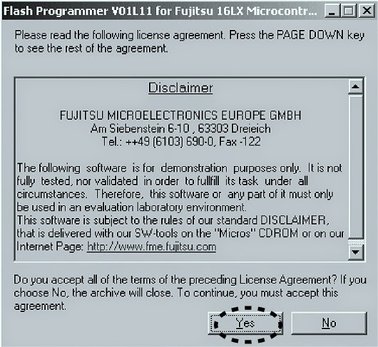
* Click "Yes"
* Click Next
* Check complete, and click next
* Click install
* The status bar appears; click Next
Writing Procedure
* Disconnect the mains cord from the unit.
* Connect RS 232C on the connection JIG and Serial Port of windows PC with RS-232C cable.
* Turn the Mode Selector switch [SW401] of connection JIG to the MICOM UPGRADE side.
* Connect the connection JIG to SERVICE PORT in the rear panel of the unit.
* Connect the mains cord to the unit.
* Press the Power On/Off button, on the unit.  Launch up the FUJITSU Flash MCU programmer (FMC16LX)
* Click Start > Programs > FUJITSU FLASH MCU programmer & FMC16lx.
* Click 'Set Environment"
* Choose the using serial port and click OK.
* Choose MB90F352C/S/CS in Target Micro-controller.
* Select writing data and click Open.
* Click 'Full operation [D+E+B+P]
* Click OK.
* Close the FUJITSU MCU Programmer.
* Disconnect mains cord from the unit.
* Disconnect JIG from the unit.
* Check version

HOW TO UPDATE DAB MICROPROCESSOR – MARANTZ ST-15S1 – DAB / FM / AM Tuner

DAB PROCESSOR UPDATE
Necessary Equipment
* Windows PC (OS: Windows2000 or Windows XP) with parallel port.
* Parallel cable straight type [25 pin male – 25 pin female]
* Connection JIG: ST-7001 DAB/MICOM UPGRADE BOARD (90M-ST7001JIG)
* Writing software and several files [DAB folder: include fast DRE310 Programmer.exe, install.bat, etc….]
* Writing data [Flash _DRE310_EVMSP | SLAVE_20050701_TBK_01_002_HE.bin]  File name will change according to release date.
Install procedure
Press right button of mouse on the install.bat, and choose the Edit in menu.
The text which copies ‘wdpnp.sys’ and ‘windrvr.sys’ file to the system folder of Windows is described.  Check the following texts.  When text is different, correct it, the save as filename. 
* Click X icon and close.
* Double click 'install.bat'
* Command prompt is launched, and files are copied.
* Check that the files have been copied.
* Press Enter or Space button, and command prompt closes automatically.
Writing procedure.
* Disconnect the mains cord from the unit.
* Connect parallel connector on the connection JIG and Parallel Port of windows PC with parallel cable.
* Turn the MODE SELECTOR switch [SW401] of the connection JIG to the DAB UPGRADE side.
* Connect the connection JIG to SERVICE PORT in the rear panel of the unit.
* Connect mains cord to the unit.
* Press the POWER ON/OFF button, and turn on the unit.
* Double click fast DRE310 programmer.exe
* DRE310| System Programmer is launched.
* The same as File Name of DataFlash is displayed.
* When a file name is different, change is required for the right file name.
* Check include this device in DataFlash.
* Choose Erase operation.
* Click execute.
* The data of DAB microprocessor is erased.  Erased Ok, appears in status.
* Choose Program and Verify in Operation.
* Click Execute.
* Writing data is written and verify.
* Click X icon, and close.
Press the Power On/Standby button, and turn off the unit.
Disconnect mains cord from the unit.
Disconnect connection JIG from the unit.
Check version.

Monday, 1 April 2019

MARANTZ PM6010-OSE _ INTEGRATED AMPLIFIER - SCHEMATIC [CIRCUIT DIAGRAM]

MARANTZ PM6010-OSE - SCHEMATIC [Circuit Diagram] _ Integrated Amplifier

Integrated Amplifier_Used semiconductors _ 2SC5198_2SA1941_AN7062P_NJM2068_TMP47C200BN
IDLING CURRENT ADJUSTMENT
  Before switching the power ON, set the master volume control to the minimum position and the balance volume to the center positions. Also set semi-fixed resistors R755(Lch) and R756(Rch) on PCB P701 to the center positions.
  Each of the cement resistors R767(Lch) and R768(Rch) on the PCB P701 is provided with three test points.  Connect a digital voltmeter, set for the DC voltage input, to the test points at the two extremities of the three test points of R767 or R768.
  After the setup above, switch the power ON, and adjust semi-fixed resistors R755(Lch) and R756(Rch) on PCB P701 according to the digital voltmeter reading. The target setting value is 10 mV(50 mA) for both the Lch and Rch.
SCHEMATICS [CLICK ON THE PICTURES TO ZOOM IN]
SYSTEM CONTROL

Saturday, 30 March 2019

MARANTZ - PM6010F - STEREO AMPLIFIER - SCHEMATIC

MARANTZ - PM6010F - STEREO AMPLIFIER - SCHEMATIC

Used ICs - TMP47C200BN_LB1630_NJN206800_AN7062P_TA7317P
ADJUSTMENT OF IDLING CURRENT TO POWER AMPLIFIER
* Before switching the power ON, set the master volume control to the minimum position and the balance volume to the center positions. Also set semi-fixed
resistors R755(L ch) and R756(R ch) on PCB P701 to the center positions.
* Each of the cement resistors R767(L ch) and R768(R ch) on the PCB P701 is provided with three test points.  Connect a digital voltmeter, set for the DC voltage
input, to the test points at the two extremities of the three test points of R767 or R768.
* After the setup above, switch the power ON, and adjust semi-fixed resistors R755(L ch) and R756(R ch) on PCB P701 according to the digital voltmeter reading. The target setting value is 10 mV(50 mA) for both the L ch and R ch.
SYSCON - SCHEMATIC & PWB
MAIN AMP - SCHEMATIC & PWB
CLICK ON THE PICTURES TO MAGNIFY

Tuesday, 19 March 2019

MARANTZ - CD-7300 - SERVICE MODE - ERROR CODE DISPLAY - EMERGENCY EJECT

MARANTZ - CD-7300 - SERVICE MODE - ERROR CODE DISPLAY - Emergency Eject


SERVICE MODE
  • While pressing DISPLAY and QUICK REPLAY buttons, press POWER button.  Mode0 (Display :   Ver : P00 Version number of the micro computer is displayed).  Status: [FOCUS OFF] [SPINDLE OFF] [RADIAL OFF] [MUTE ON]
  • While pressing ►► and ◄◄ buttons, the sledge  moves toward the outer edge.  Release the button makes the sledge return to the origin.
  • Press EASY JOG or NEXT ►►| button on the remote to go to Mode 1.
Mode 1 (Display : Ver : P01). Status: [FOCUS ON] [SPINDLE OFF] [RADIAL OFF] [MUTE ON].
  • Press NEXT ►►| button to go to Mode 2.
  • Press PREV |◄◄ button to go to Mode 0.
Mode 2 (Display : Ver : P02).  Status: [FOCUS ON] [SPINDLE ON] [RADIAL OFF] [MUTE ON]
  • Press NEXT ►►| button to go to Mode 3.
  • Press PREV |◄◄ button to go to Mode 1.
Mode 3 (Display : Ver : P03).  Status: [FOCUS ON] [SPINDLE ON] [RADIAL ON] [MUTE OFF]
  • Press PREV |◄◄ button to go to Mode 1.
  • In this Service Mode, all of the following button functions work in any status.
  1. Press DISPLAY button to light up all the FL segments. Press it again then each FL segment lights up one by one.
  2. Press STOP button. Then press a button on the unit. The name of the button is displayed. Pressing a button on the remote displays the RC-5 code of the button.
  3. Press PLAY button in Mode 1, 2 or 3 then normal operation can be performed. If an error occurs the error number is displayed.
Terminating Service Mode
Turn off power to quit Service Mode.
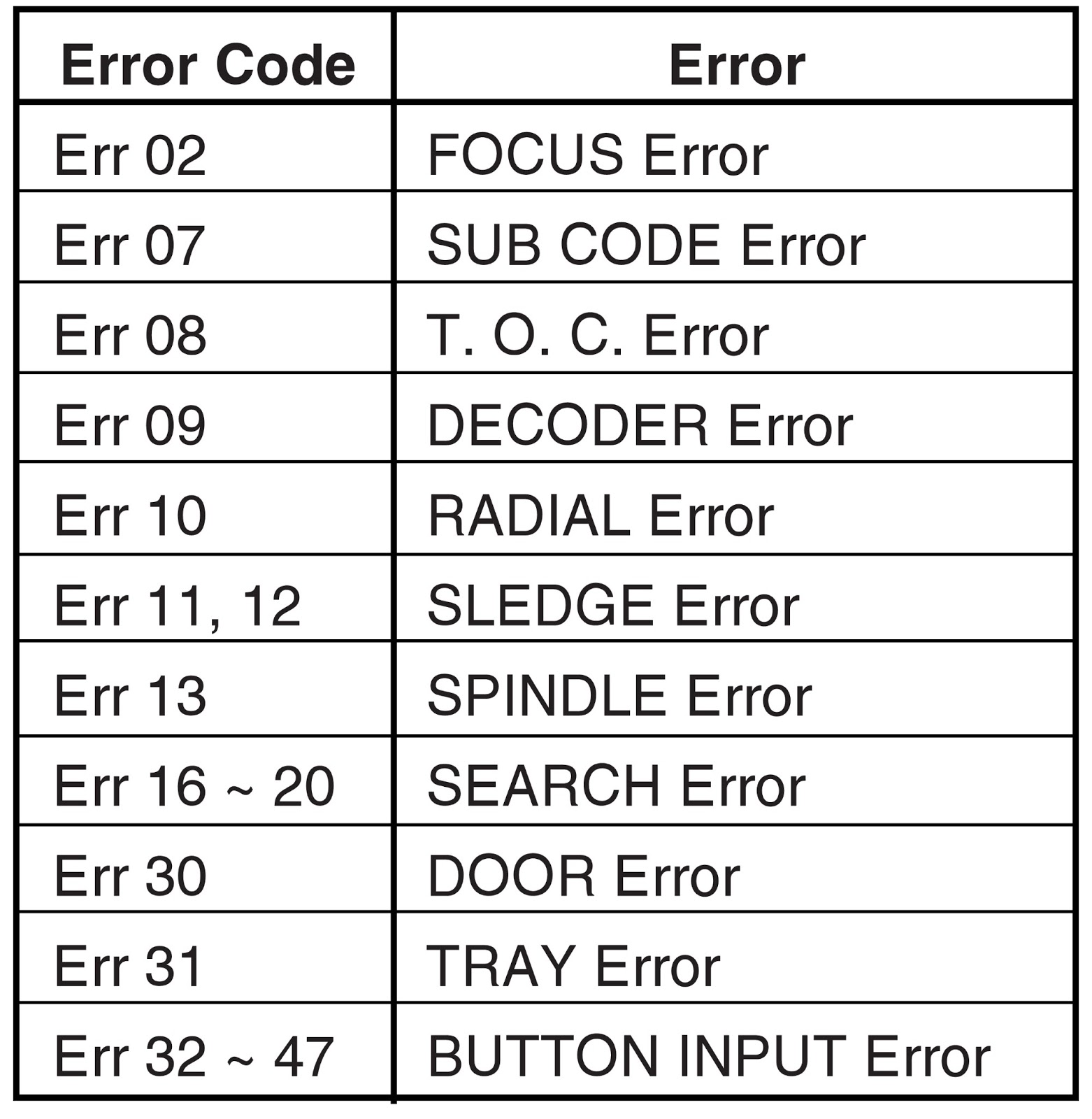
ERROR CODES & DETAILS
DISASSEMBLY
Emergency Eject
  • To open the stucked tray, insert a pin into the eject pinhole and push the eject lever.
  • Use a pin φ 4mm or less.
This picture shows the unit upside down. The eject lever is pointed by the arrow.  The lever is thin so aim the narrow area carefully.
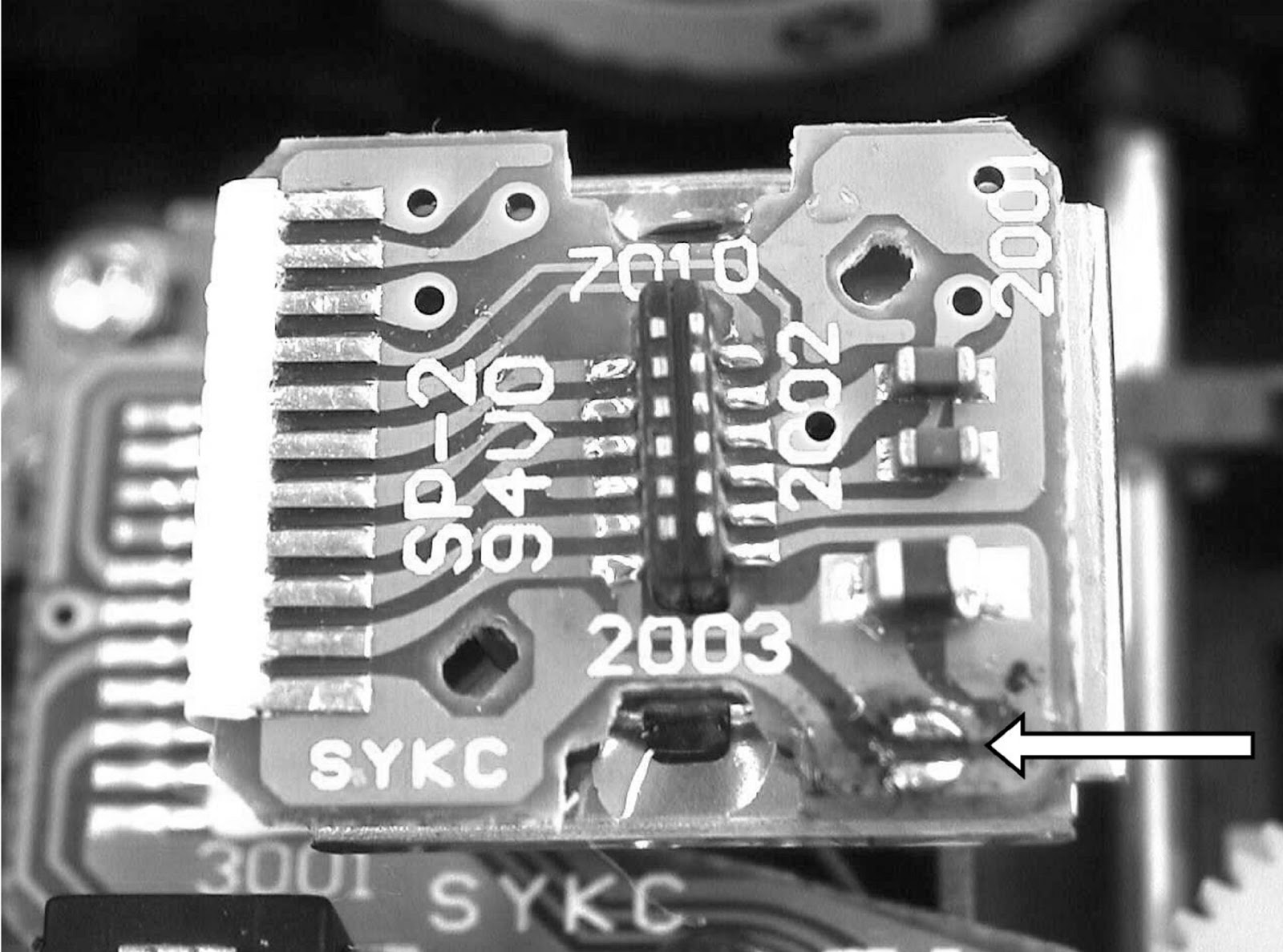
When removing the flat wire PS01, connecting the optical pick up and the CD decoder board, short-cut the two lands pointed by the arrow with solder. Otherwise the laser diode may be damaged by static electricity.
CD Decoder Board (PS01) Repair
When Repairing the CD decoder board PS01, you can fix the board on the loader unit as shown in the picture below with the flat wires that are provided as service parts.
Disk Tray Open/Close Speed Adjustment
  • Open/Close speed of the tray can be changed.
  • When vibration occurs upon tray open/close and some unusual behavior happens, change the tray speed to stop vibration.

Vibration on Disc Tray Open / Close
Step 1.  With pressing DISPLAY and QUICK REPLAY buttons, press POWER button.
Step 2.  Press EASY JOG button. “T-OnTime 015”(means Tray On Time 015ms default) is displayed.
Turn n EASY Jogtrot change tray open/close speed from 000 to 255ms. Turn the number smaller to make the open/close speed slower. Turn the number bigger to make the speed faster. Set bigger number to stop the tray vibration. But the open/close speed becomes faster. Press EASY JOG button again.
The display changes as shown below so you can change other parameters for the open/close speed.
Step 3.Press EASY JOG button to complete adjustment.
Step 4.Press STOP button to store the settings in memory.
To reset all the settings to default status, press number 0 button in Service Mode 0  (Display : Ver   P00).
When miss-operated, press number 0 button to retry.
{Click on pictures to Zoom In}